QRIPRIMUSNXTimplantable cardioverter defibrillator
BIOTRONIK SE & Co. KG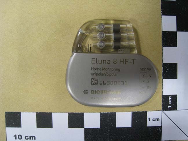
Click to zoom
Application Details
- Equipment Class
- TNT - Licensed Non-Broadcast Transmitter Worn on Body
- Date of Grant
- Dec 10, 2013
- Application Purpose
- Original Equipment
- Date of Application
- Sep 09, 2013
- Equipment Note
- implantable cardioverter defibrillator
- Frequency Range
- 402.45000000 - 404.85000000
- Company
- BIOTRONIK SE & Co. KG
- Country
- Germany
Documents & Files
Document Text
Text extracted from the exhibit documents filed with the FCC. Open a document above to read the original.
Attestation Statements
Response to FCC Equipment Authorization in Blue below the findings: Applicant: BIOTRONIK SE & Co. KG FCC ID: QRIPRIMUSNXT 731 Confirmation Number: EA310957 Adminstrative Review by Evelyn Cherry: Correspondence Reference Number: 44433 Date of Original E-Mail: 9/16/2013 FCC: An administrative review of this application filing shows that the required fee has been paid and verified. Please sign and date the exhibit under operational description. The confidentiality request must reference both Sections of the FCC Rules 0.457 and 0.459 as the authority for granting confidentiality. The exhibit uploaded beginning with the #24 requires a signature, date if not dated, and the request must be provided on official company's letter head. Response by applicant: 1. A revised version of the confidentiality letter signed by the applicant is attached. The document number is 05_PRIMUSXT ConReq-U rev1. Please be informed that the applicant asks for permanent confidentiality of the internal pictures and has this document type added to the list. The implant is completely sealed by welding and cannot be opened without destroying. Furthermore we attached versions of the 95I test report without pictures of the device for the public database with document numbers: “14a_PRIMUSNXT TestRep 95I without product photo”s and “14b_PRIMUSNXT TestRep 15.209 without product photos” 2. A signed version of the short term confidential request: 24_PRIMUSNXT ShortConReq rev1. is attached. It is dated and provided on company’ letter head Technical Review by Travis Thul: Correspondence Reference Number: 44440 Date of Original E-Mail: 9/18/2013 1. FCC: The Equipment Code listed under Equipment Specifications is currently set to TNB – Licensed Non-Broadcast Station Transmitter. This designation should be set to TNT – Non-Broadcast Transmitter Worn on Body. This change has been made to your application and requires no action on the part of the submitter. Response by applicant: Thanks for the correction, we are going to specify all future application for med radio implants to TNT. 2. FCC: Per 47 CFR 95.1215, the specific verbiage found in paragraph (a) of that section must be included verbatim with each device. This is acknowledged in the exhibit titled “06_07 Labeling_PRIMUSNXT”, but is not reflected in the exhibit titled “15_PRIMUSNXT UserMan” (the User’s Manual). Please update documents in accordance with 47 CFR 95.1215. Response by applicant: A revised version of the user manual is attached; document name: 15_PRIMUSNXT UserMan rev1. It shows the exact wording of the text statement per 47 CFR 95.1215 on page 19. 3. FCC: The exhibit titled “11_PRIMUSNXT OpDes” indicates conformity with 47 CFR Part 24. This is erroneousas Part 24 is specific to Personal Communications Services. Please update documents accordingly Response by applicant: A revised version of the operational description is attached, document number: 11_PRIMUSNXT OpDes rev1. The correct rule part is 95I 4. FCC: The Emission Designator within the submitted Equipment Specifications has been listed as 188KF1D (equating to a bandwidth of 188 kHz). However, the type of emission within the exhibit titled “11_PRIMUSNXT OpDes”, is given as 230KF1D (equating to a bandwidth of 230 kHz). Please clarify this deviation and update package accordingly Response by applicant: A revised version of the operational description is attached, document number: 11_PRIMUSNXT OpDes rev1. The bandwidth is changed to the exact measured value of 188 kHz, see also test report. 5. FCC: The exhibit titled “12_RPIMUSNXT BlkDia” shows a 27nH inductor connected outside of the main device housing. It is unclear what role this inductor plays during communications between the primary device and the programming unit (referred to as the “Programmer” within the User’s Manual). Please clarify. If the inductor functions as an antenna, please update documentation to reflect as much, under what circumstances this is the case, and describe the communications link Response by applicant: The 27 nH coil is the radiation element of the 64kHz coil telemetry feature of the device. It is a near field communication system between a magnetic programmer head and the implant and hardly detectable even in short distance. Test report 14b_PRIMUSNXT TestRep 15.209 shows that the transmit power at 64 kHz is more than 40dB below the spurious emission limit and the telemetry function is not subject of certification. 6. FCC: The power output value within the submitted Equipment Specifications indicates a maximum output power of 0.8uW (-30.97dBm). This value deviates from the worst-case maximum output power of 93.154uW shown within the exhibit “18a_PRIMUSNXT RFExp”. The output power value has been updated to reflect the value found within the exhibit and the change has been noted in the package. Response by applicant: The maximum output power of 0.8uW in the rf report and Equipment Specification is radiated e.i.r.p. according to the requirements of 95.639(f). The RFExp calculation is based on the maximum conducted output power (93.154uW) to consider the worst case near field effects. The “bad” antenna gain of more than factor -100 (-21.6 dBi) is due to the very limited room for the antenna dimension at a relatively lower frequency of about 400 MHz. 7. FCC: The exhibit titled “14b_PRIMUSNXT TestRep 15.209” shows testing using a center frequency of 64 kHz. However, all supporting documentation omits further description or elaboration of this transmitting mode. It should be noted that, per 47 CFR 15.201(a), devices operating below 490 kHz in which all emissions are at least 40 dB below the limits in 15.209 shall be verified per 47 CFR Part 2, subpart J. If this is the case, the package will need to be updated accordingly Response by applicant: The report 14b_PRIMUSNXT TestRep 15.209 was submitted to demonstrate that the coil telemetry (64kHz) function transmitted by the 27mH coil of the device is far below the 40 dB below 15.209 limit and…
Text truncated - open the document above for the full version.
External Photos
External Photos page 1 Model No.:Eluna 8, Epyra 6, Epyra 8, Etrinsa 6, Etrinsa 8 FCC ID: QRIPRIMUSNXT IC: 4708A-PRIMUSNXT Eurofins Product Service GmbH Storkower Str. 38C, D-15526 Reichenwalde, Germany External Photos page 2 Model No.:Eluna 8, Epyra 6, Epyra 8, Etrinsa 6, Etrinsa 8 FCC ID: QRIPRIMUSNXT IC: 4708A-PRIMUSNXT Eurofins Product Service GmbH Storkower Str. 38C, D-15526 Reichenwalde, Germany External Photos page 3 Model No.:Eluna 8, Epyra 6, Epyra 8, Etrinsa 6, Etrinsa 8 FCC ID: QRIPRIMUSNXT IC: 4708A-PRIMUSNXT Eurofins Product Service GmbH Storkower Str. 38C, D-15526 Reichenwalde, Germany
RF Exposure Info
Technical Report 3147205 Primus SAR Analysis Rev. E Page 1 of 10 Letter Revisions Date Approval A Original 13-11-2008 BPS B Correct doc. Number on pages 2 through 9 20-11-2008 BPS C Updated references to FCC regulations 21-01-2010 BPS D Updated SAR Results 22-02-2010 BPS E Deleted duty-cycle averaging from SAR analysis 02-03-2010 BPS 1 Purpose The purpose of this report is to document the Specific Absorption Rate (SAR) computational analysis of the Biotronik Primus pacemaker. 2 Conclusion The Primus pacemaker, employing an ultra-low power RF transmitter, complies with the SAR regulatory limits specified in 47 CFR 95.1221, §2.1093, and §1.1307(b)(2). The Primus pacemaker’s maximum worst-case SAR is 2.5218e-003 W/kg, averaged over 1 gram of tissue. The regulatory limit specified in 47 CFR 2.1093 is 1.6 Watts/kg, averaged over 1 gram of tissue. As such, the Primus pacemaker’s SAR level complies with the FCC regulatory limit with a margin of 28 dB. 3 Applicability This report is applicable to the Primus family of pacemakers that use the same MedRadio RF transmitter circuitry and antenna structure noted in this report. 4 Document History Ver. A 13-11-2008 Initial Release Ver. B 20-11-2008 Corrected doc. Number on pages 2 through 9 Ver. C 21-01-2010 Updated per FCC correspondence Ver. D 22-02-2010 Updated SAR Results Ver. E 02-03-2010 Removed duty-cycle averaging from SAR analysis 5 References 47 CFR 95.1221 RF Exposure 47 CFR 2.1093 Radio Frequency Radiation Exposure Evaluation: Portable Devices 47 CFR 1.1310 Radio Frequency Radiation Exposure Limits. 6 Definitions MedRadio Medical Device Radiocommunication Service Periodic Transmission Infrequent RF signal transmission, on a periodic basis, from a transmitter to a receiver. Max-Hold Instrument display mode that indicates and displays the maximum detected signal level. Conducted Measurements Electrical measurements made using hardwire connections (not antennas) to the DUT DUT Device Under Test Technical Report 3147205 Primus SAR Analysis Rev. E Page 2 of 10 7 Test Equipment The following equipment was used to perform the tests outlined in this report. ITEM DESCRIPTION MFGR. MODEL SERIAL NUMBER CALIBRATION DATE CALIBRATION DUE DATE IMP Implant module (Device Under Test) Biotronik Primus 06082200-03-D 358212 N/A N/A SA RF Spectrum Analyzer Rohde & Schwarz FSL 616 100288 14-05-2008 31-05-2009 SENSOR RF Power Meter Sensor Agilent 8481A MY41095529 16-05-2008 31-05-2009 PM Power Meter/Freq Counter Agilent 53147A US40470964 16-05-2008 31-05-2009 NET RF Network Analyzer Agilent 8753ES US39170321 28-07-2008 31-07-2009 CALKIT 3.5 mm Calibration Kit Agilent 85033D 3423A04725 14-11-2005 14-11-2008 CABLES RF Cables, 50 Ohm Coax with SMA connectors Pasternack Assorted N/A N/A N/A 7.1 Photograph of the Primus pacemaker Figures 7.1.1 and 7.1.2 are photos of the Biotronik Primus pacemaker. The loop antenna, embedded near the perimeter of the epoxy header, is evident in Figure 7.1.2. Figure 7.1.1 Front view of the Primus Pacemaker. Figure 7.1.2 Rear view of the Primus pacemaker. 8 Primus’ Specific Absorption Rate (SAR) Analysis Biotronik pacemakers utilize an ultra-low power RF transmitter to send a patient’s cardiac medical condition to a physician for evaluation. The amount of radiated power absorbed by the human body using this technology can be defined by a measure termed the Specific Absorption Rate (SAR). ANSI and the IEEE have defined the maximum SAR levels that can be safely used in these applications, and these limits are included in the FCC’s regulations for the Medical Device Radiocommunication Service (MedRadio). Certification of medical-implant transmitters under the FCC Part 95 MedRadio requires a measurement or Finite Difference Time Domain (FDTD) computational analysis of the SAR associated with the presence of non-ionizing radio frequency (RF) transmissions. This report details the SAR computational analysis for the ultra-low power RF transmitter employed in the Primus pacemaker. Technical Report 3147205 Primus SAR Analysis Rev. E Page 3 of 10 8.1 Method of SAR Analysis The computational software used for this FDTD analysis was Remcom XFDTD Version 6.5.14.6. This software was used to convert a Biotronik 3-dimensional CAD engineering model of the pacemaker to a 3D rectangular-grid FDTD computational space. Adaptive cell-size meshing was employed in the FDTD computational space to achieve accurate modeling while also maintaining a reasonable limit on the computational memory requirements. To accurately model the SAR, a maximum cell size of 0.5 mm was used; except in the region of the antenna structure where the cell size was further reduced to 0.05 mm. As the cell size is extremely small, it is not practical to include a model of the upper human torso in the analysis. However, since previous experience using XFDTD modeling has shown that the region of maximum SAR is concentrated very near the antenna structure, the region surrounding the pacemaker was modeled using a material simulating the dielectric properties of human muscle at 403.5 MHz. As such, the computational model used in this study was restricted to 2 cm of muscle tissue surrounding the implant, and this resulted in a computational analysis encompassing approximately 38.5 million cells. To eliminate reflections at the boundary of the modeled space, the region beyond the meshed volume was modeled using perfectly matched layers (PML absorbing boundary). Figure 8.1.1 below shows a 3D view of the SAR computational space, and the loop antenna in the Primus pacemaker header can be clearly identified. The computational space used was 9.3 x 8.5 x 4.8 cm 3 , or approximately 379.4 cm 3 . This volume is more than sufficient for computing 1gram average SAR levels as required by the FCC. Figure 8.1.1 3D view of the Primus pacemaker embedded in tissue material for the SAR analysis. The use of a small cell size allowed all the elements of the header and antenna structure to be realized and accurate…
Text truncated - open the document above for the full version.
Test Report
Test Report No.: G0M-1304-2799-TFC209L-V01 Eurofins Product Service GmbH Storkower Str. 38c, D-15526 Reichenwalde, Germany Page 1 of 24 FCC TEST REPORT FCC 47 CFR Part 15C Industry Canada RSS-310 License exempt radio equipment Report Reference No. .................... : G0M-1304-2799-TFC209L-V01 Testing Laboratory ........................ : Eurofins Product Service GmbH Address ............................................ : Storkower Str. 38c 15526 Reichenwalde Germany Accreditation .................................... : A2LA Accredited Testing Laboratory, Certificate No.: 1983.01 FCC Filed Test Laboratory, Reg.-No.: 96970 IC OATS Filing assigned code: 3470A Applicant’s name ........................... : BIOTRONIK SE & Co. KG Address ............................................ : Woermannkehre 1 12359 Berlin GERMANY Test specification: Standard ........................................... : 47 CFR Part 15C RSS-310, Issue 3, 2010-12 RSS-Gen, Issue 3, 2010-12 ANSI C63.4:2009 Equipment under test (EUT): Product description IPG / Implantable Pulse Generator Model No. Eluna 8-HF-T Hardware version 6082220-03 Rev 0A Firmware / Software version GTR-12-0173-A FCC-ID: QRIPRIMUSNXT IC: 4708A-PRIMUSNXT Test result Passed Test Report No.: G0M-1304-2799-TFC209L-V01 Eurofins Product Service GmbH Storkower Str. 38c, D-15526 Reichenwalde, Germany Page 3 of 24 Additional comments: The report applies to all model stated in the “Primus NXT Family Listing” issued by the Manufacturer Model Description Eluna 8 SR One chamber , only Coil telemetry Eluna 8 SR-T One chamber , Coil telemetry and RF Transceiver Eluna 8 DR Two chambers , only Coil telemetry Eluna 8 DR-T Two chamber , Coil telemetry and RF Transceiver Eluna 8 HF-T Three chambers , Coil telemetry and RF Transceiver Epyra 6 SR-T One chamber , Coil telemetry and RF Transceiver Epyra 6 DR-T Two chambers , Coil telemetry and RF Transceiver Epyra 8 SR-T One chamber , Coil telemetry and RF Transceiver Epyra 8 DR-T Two chambers , Coil telemetry and RF Transceiver Epyra 8 HF-T Three chambers , Coil telemetry and RF Transceiver Etrinsa 6 SR One chamber , only Coil telemetry Etrinsa 6 SR-T One chamber , Coil telemetry and RF Transceiver Etrinsa 6 DR Two chambers , only Coil telemetry Etrinsa 6 DR-T Two chambers , Coil telemetry and RF Transceiver Etrinsa 8 SR-T One chamber , Coil telemetry and RF Transceiver Etrinsa 8 DR-T Two chambers , Coil telemetry and RF Transceiver Etrinsa 8 HF-T Three chambers , Coil telemetry and RF Transceiver The BIOTRONIK PRIMUS NXT family of products includes the following models : Eluna, Epyra and Etrinsa . All models comprise identical internal electronic including a low frequency telemetry coil and packaged in titanium cases with a header where the leads connect. The T Devices include additional an internal RF Transceiver and an antenna within the header. The internal electronic of HF-T devices differs slightly from SR and DR devices to include the third channel electronic. Therefore the device under test is three chambers model Eluna 8 HF-T. The PRIMUS NXT models contain a different therapeutic feature set. The feature differences comprising only software. Evaluation measurements were performed for worst case with the Eluna 8-HF-T, as the most complex model, was selected for the measurements. Test Report No.: G0M-1304-2799-TFC209L-V01 Eurofins Product Service GmbH Storkower Str. 38c, D-15526 Reichenwalde, Germany Page 4 of 24 REPORT INDEX 1 EQUIPMENT (TEST ITEM) DESCRIPTION 5 1.1 Photos – Equipment External 6 1.2 Photos – Equipment Internal 7 1.3 Photos – Test setup 9 1.4 Supporting Equipment Used During Testing 10 1.5 Test Modes 11 1.6 Test Equipment Used During Testing 12 1.7 Sample emission level calculation 13 2 RESULT SUMMARY 14 3 TEST CONDITIONS AND RESULTS 15 3.1 Test Conditions and Results – Occupied Bandwidth 15 3.2 Test Conditions and Results – Fundamental field strength emissions 18 3.4 Test Conditions and Results – Receiver radiated emissions 20 ANNEX A Transmitter radiated spurious emissions 22 ANNEX B Receiver radiated spurious emissions 24 Test Report No.: G0M-1304-2799-TFC209L-V01 Eurofins Product Service GmbH Storkower Str. 38c, D-15526 Reichenwalde, Germany Page 5 of 24 1 Equipment (Test item) Description Description IPG / Implantable Pulse Generator Model Eluna 8-HF-T Serial number None Hardware version 6082220-03 Rev 0A Software / Firmware version GTR-12-0173-A FCC-ID QRIPRIMUSNXT IC 4708A-PRIMUSNXT Equipment type End product Radio type Transceiver Radio technology custom Operating frequency range 64 kHz Frequency range F MID 64 kHz Modulations OOK Number of channels 1 Channel spacing None Number of antennas 1 Antenna Type integrated Model loop antenna Manufacturer Biotronik SE & Co. KG Gain -21.6 dBi (Determined by measurements) Manufacturer BIOTRONIK SE & Co. KG Woermannkehre 1 12359 Berlin GERMANY Power supply V NOM 2.8 VDC (Lithium-Battery) V MIN N/A V MIN N/A AC/DC-Adaptor Model N/A Vendor N/A Input N/A Output N/A Test Report No.: G0M-1304-2799-TFC209L-V01 Eurofins Product Service GmbH Storkower Str. 38c, D-15526 Reichenwalde, Germany Page 6 of 24 1.1 Photos – Equipment External MODEL ELUNA 8 HF-T TOP MODEL ELUNA 8 HF-T BOTTOM MODEL ELUNA 8 DR-T TOP MODEL ELUNA 8 DR-T BOTTOM MODEL EPYRA 6 SR-T TOP MODEL EPYRA 6 SR-T BOTTOM Test Report No.: G0M-1304-2799-TFC209L-V01 Eurofins Product Service GmbH Storkower Str. 38c, D-15526 Reichenwalde, Germany Page 9 of 24 1.3 Photos – Test setup Test setup – Radiated emissions Test Report No.: G0M-1304-2799-TFC209L-V01 Eurofins Product Service GmbH Storkower Str. 38c, D-15526 Reichenwalde, Germany Page 10 of 24 1.4 Supporting Equipment Used During Testing Product Type* Device Manufacturer Model No. Comments None *Note: Use the following abbreviations: AE : Auxiliary/Associated Equipment, or SIM : Simulator (Not Subjected to Test) CABL : Connecting cables Test Report No.: G0M-1304-2799-TFC209L-V01 Eurofins Product Service GmbH Storkower Str. 38c, D-15526 Reichenwalde, Ge…
Text truncated - open the document above for the full version.
Contact Information
Applicant
Dirk Koenig(Senior Manager Regulatory Affairs)
Test Firm
Eurofins Product Service GmbHRobert Kschiwan-Kaspar
Technical Specifications
| # | Rule Parts | Frequency Range | Power Output | Emission | Tolerance |
|---|---|---|---|---|---|
| 1 | 95I | 402.45 MHz - 404.85 MHz | 0.80 µW | 188KF1D | 9.0000000000 ppm |
Other Applications from BIOTRONIK SE & Co. KG

QRI-CMS4GWWQ1
Jul 20, 2026CardioMessenger Smart / Telemonitoring System
Equipment Class
JAB - Part 15 Class B Digital DeviceQRI-BEXWW1
Jan 23, 2026Status interrogation system for implantable pacemakers, defibrillators and monitors
Equipment Class
NII - Unlicensed National Information Infrastructure TX
QRI-BM2610P2
May 07, 2023Implantable Cardiac Monitor
Equipment Class
TNT - Licensed Non-Broadcast Transmitter Worn on Body
QRI-QCONNECT
Jan 23, 2023Data Gateway for Electrophysiology Lab
Equipment Class
PCB - PCS Licensed Transmitter
QRI-IPG2267P2
Jan 15, 2023Implantable Pulse Generator
Equipment Class
TNT - Licensed Non-Broadcast Transmitter Worn on Body