QRIRENAMICMedical Programmer and Monitoring Device
BIOTRONIK SE & Co. KG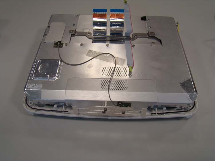
Click to zoom
Application Details
- Equipment Class
- TNB - Licensed Non-Broadcast Station Transmitter
- Date of Grant
- Oct 24, 2010
- Application Purpose
- Original Equipment
- Date of Application
- Oct 24, 2010
- Equipment Note
- Medical Programmer and Monitoring Device
- Frequency Range
- 402.00000000 - 405.00000000
- Company
- BIOTRONIK SE & Co. KG
- Country
- Germany
Documents & Files
Document Text
Text extracted from the exhibit documents filed with the FCC. Open a document above to read the original.
Users Manual
3Table of Contents Table of Contents Table of Contents Introduction . . . . . . . . . . . . . . . . . . . . . . . . . . . . . . . . . . . . . . . . . . . . . . . . . . 5 About the Device . . . . . . . . . . . . . . . . . . . . . . . . . . . . . . . . . . . 5 About this Technical Manual. . . . . . . . . . . . . . . . . . . . . . . . . . 6 Safety During Use . . . . . . . . . . . . . . . . . . . . . . . . . . . . . . . . . . . . . . . . . . . . . 7 Intended Medical Use . . . . . . . . . . . . . . . . . . . . . . . . . . . . . . . 7 Required Expertise . . . . . . . . . . . . . . . . . . . . . . . . . . . . . . . . . 8 Residual Risk . . . . . . . . . . . . . . . . . . . . . . . . . . . . . . . . . . . . . . 9 General Safety Instructions . . . . . . . . . . . . . . . . . . . . . . . . . 10 Operating Conditions . . . . . . . . . . . . . . . . . . . . . . . . . . . . . . . 12 Electromagnetic Interference. . . . . . . . . . . . . . . . . . . . . . . . 14 Maintenance, Care and Disposal . . . . . . . . . . . . . . . . . . . . . 15 Startup . . . . . . . . . . . . . . . . . . . . . . . . . . . . . . . . . . . . . . . . . . . . . . . . . . . . . 17 Device Overview . . . . . . . . . . . . . . . . . . . . . . . . . . . . . . . . . . . 17 Transportation and Setup . . . . . . . . . . . . . . . . . . . . . . . . . . . 21 Connections and Cables . . . . . . . . . . . . . . . . . . . . . . . . . . . . 23 Power Supply . . . . . . . . . . . . . . . . . . . . . . . . . . . . . . . . . . . . . 28 Switching On and Off . . . . . . . . . . . . . . . . . . . . . . . . . . . . . . . 29 Using Renamic . . . . . . . . . . . . . . . . . . . . . . . . . . . . . . . . . . . . . . . . . . . . . . . 31 Keys, Displays and Signals . . . . . . . . . . . . . . . . . . . . . . . . . . 31 Emergency Programs . . . . . . . . . . . . . . . . . . . . . . . . . . . . . . 33 Programming Head . . . . . . . . . . . . . . . . . . . . . . . . . . . . . . . . 36 Communication with Active Implanted Devices . . . . . . . . . 38 Using the Internal Printer . . . . . . . . . . . . . . . . . . . . . . . . . . . 39 Using an External Printer . . . . . . . . . . . . . . . . . . . . . . . . . . . 42 ECG and IEGM Functions. . . . . . . . . . . . . . . . . . . . . . . . . . . . 43 Appendix . . . . . . . . . . . . . . . . . . . . . . . . . . . . . . . . . . . . . . . . . . . . . . . . . . . . 45 Technical Data . . . . . . . . . . . . . . . . . . . . . . . . . . . . . . . . . . . . 45 Scope of Delivery and Accessories. . . . . . . . . . . . . . . . . . . . 49 Electromagnetic Compatibility in Compliance with EN 60601-1-2:2007 . . . . . . . . . . . . . . . . . . . . . . . . . . . . 51 Country-Related Information . . . . . . . . . . . . . . . . . . . . . . . . 54 Symbols on the Components . . . . . . . . . . . . . . . . . . . . . . . . 55 Legend for the Label . . . . . . . . . . . . . . . . . . . . . . . . . . . . . . . 57 Directories . . . . . . . . . . . . . . . . . . . . . . . . . . . . . . . . . . . . . . . . . . . . . . . . . . 59 List of Keywords. . . . . . . . . . . . . . . . . . . . . . . . . . . . . . . . . . . 59 377213--D 4Table of Contents 5 1Introduction Introduction1xxxxxx--XDoc-classRenamic About the Device General descriptionRenamic is a portable programmer and monitoring device. According the customer specification the device is equipped with a GSM, UMTS or WIFI module. This enables the direct export of patient data from Renamic to hospital or practice networks. It is used during the implantation procedure and follow-up of implantable pulse generators and ICDs (implantable cardioverter-defibrillators). Primary functionsThe device has the following primary functions: FunctionPurpose Programming and testing functions Program BIOTRONIK pacemakers and ICDs during the implantation procedure or follow-ups ECG recorder and ECG monitor Display and printout of up to three leads of surface ECGs, as well as up to three intracardiac deriva- tions (IEGMs) and the corresponding event markers, in real-time Data managementStore parameter values and ECG/IEGM recordings for computer-aided archiving and evaluation DocumentationPrint out follow-up reports using the internal and/ or external printer 6Introduction About this Technical Manual ObjectiveThis technical manual provides the user with all the safety information required to use the Renamic programmer. The following topics are covered in this manual: •Device startup •Interrogation, testing and programming of implantable pulse generators and cardioverter-defibrillators (ICD) Targe t groupThis technical manual is intended for physicians and trained medical personnel who are familiar with the following: •The use of implantable pulse generators and ICDs •The risks and possible complications associated of using these systems Additional requirements include: •Medical knowledge: — Basic medical knowledge of the therapy applied — Training in the handling and programming of implantable pulse generators and ICDs •Technical knowledge: — Ability to work with a PC — Ability to use software-controlled medical devices Other technical manuals•Technical software manual for programming the intended implantable pulse generator / ICD •Technical manual for the intended implantable pulse generator / ICD 7 2Safety During Use Safety During Use2xxxxxx--XDoc-classRenamic Intended Medical Use Intended medical useThe Renamic programmer provides communication with the implantable pulse generator or ICD during the implantation procedure or follow-ups. The Renamic programmer is intended to be used for the following tasks: •Conduct sensing, pacing threshold and impedance tests •Interrogate data of the implanted device such as program parameters, recorded statistical data and episodes, as well as real-time IEGMs •Display, printout, save and export data of the implanted device for analysis and reporting purposes •Transfer parameters to the implanted device 8Safety During Use Required Expertise Required expertiseThe programmer is intended f…
Text truncated - open the document above for the full version.
External Photos
Test Report No.: G0M21004-3144-T-47 Eurofins Product Service GmbH Storkower Str. 38c, D-15526 Reichenwalde, Germany EUT Front EUT Back Page 30 of 125 Test Report No.: G0M21004-3144-T-47 Eurofins Product Service GmbH Storkower Str. 38c, D-15526 Reichenwalde, Germany EUT Left EUT Right Page 31 of 125 Test Report No.: G0M21004-3144-T-47 Eurofins Product Service GmbH Storkower Str. 38c, D-15526 Reichenwalde, Germany EUT Display Page 32 of 125
RF Exposure Info
Project No.: G0M21004-3144 18_RF Exposure compliance page 1 Model No.:RENAMIC FCC ID: QRIRENAMIC IC: 4708A-RENAMIC The EUT is a programmer / monitoring device for a Medical Implant Communications system operating under Part 95I in the 402 – 405 MHz band. The EUT is not an implant. It is used at a distance of more than 20 centimeters between the antenna and the body of the user or nearby persons and can therefore be considered a mobile transmitter per 47 CFR 2.1091. The antenna is a ¼ wave wire antenna that has a gain of 0 dBi. The maximum peak radiated power is 0.02 mW EIRP. Per 95.1221 only implant or body worn transmitters are subject to the radio frequency radiation exposure requirements specified in FCC Parts 1.1307 and 2.1093. Since the EUT is not a medical implant, and operates with such low power (<< 1mW), it is categorically excluded from routine environmental evaluation. This device is operated in a manner that ensures the public is not exposed to radio frequency energy levels in excess of the Commission's guidelines.
Test Report
EUROFINS PRODUCT SERVICE GMBH RADIO TEST - REPORT EUROPEAN STANDARD EN 301 839 FCC RULES PARTS 95 Subpart I IC RADIO STANDARDS RSS-243 FCC ID : QRIRENAMIC IC : 4708A-RENAMIC ICS Neo Renamic TEST REPORT NUMBER : G0M21004-3144-T-47 Eurofins Product Service GmbH Storkower Str. 38c, 15526 Reichenwalde, Phone +49-33631-888 0 Germany ́ Fax +49-33631-888 660 Test Report No.: G0M21004-3144-T-47 Eurofins Product Service GmbH Storkower Str. 38c, D-15526 Reichenwalde, Germany TABLE OF CONTENT 1 General information 3 1.1 Notes 3 1.2 Testing laboratory 4 1.3 Details of approval holder 5 1.4 Application details 5 1.5 Test item 5 1.6 Test standards 6 2 Technical test 7 2.1 Summary of test results 7 2.2 Test environment 7 2.3 Test Information 8 2.4 Test equipment utilized 9 2.5 Test results 10 3 Transmitter parameter 11 3.1 Frequency error 11 3.2 Emission bandwidth 12 3.3 Effective radiated power (e.r.p.) 13 3.4 Spurious emissions 14 3.5 Frequency stability under low voltage conditions 15 3.6 Unwanted radiation 16 3.7 Conducted Measurements AC power line 19 4 Receiver parameter 20 4.1 Spurious radiation 20 4.2 Monitoring system threshold power level 21 4.3 Monitoring system bandwidth 22 4.4 Scan cycle time 23 4.5 Minimum channel monitoring period 24 4.6 Channel access 25 4.7 Discontinuation of MICS session 26 4.8 Use of pre-scanned alternate channel 27 4.9 Radiated emission 28 Annex A Photos 29 Annex B Measurement diagrams “20dB Emission bandwidth” 43 Annex C Measurement diagrams “Occupied bandwidth” 50 Annex D Measurement diagrams “Radiated power” 57 Annex E Measurement diagrams “Transmitter spurious emissions, Europe” 62 Annex F Measurement diagrams “Transmitter spurious emissions, FCC” 75 Annex G Measurement diagrams “Band edge emissions” 98 Annex H Measurement diagrams “AC power line conducted emissions” 103 Annex I Measurement diagrams “Receiver spurious emissions, Europe” 106 Annex J Measurement diagrams “Receiver spurious emissions, Canada” 119 Page 2 of 125 Page 3 of 125 Test Report No.: G0M21004-3144-T-47 Eurofins Product Service GmbH Storkower Str. 38c, D-15526 Reichenwalde, Germany 1.2 Testing laboratory Eurofins Product Service GmbH Storkower Strasse 38c D-15526 Reichenwalde b. Berlin Germany Telefon : +49 33631 888 00 Telefax : +49 33631 888 66 DAR ACCREDITED TESTING LABORATORY DAR-R EGISTRATION NUMBER: DAT-P-268/08 R ECOGNIZED NOTIFIED BODY EMC R EGISTRATION NUMBER: BNetzA-bS EMV-07/61 R ECOGNIZED NOTIFIED BODY R&TTE R EGISTRATION NUMBER: BNetzA-bS-02/51-53 FCC FILED TEST LABORATORY R EG.-NO. 96970 A2LA ACCREDITED TESTING LABORATORY C ERTIFICATE NO. 1983.01 B LUETOOTH QUALIFICATION TEST FACILITY (BQTF) A CCREDITED BY BLUETOOTH QUALIFICATION REVIEW BOARD I NDUSTRY CANADA FILED TEST LABORATORY R EG. NO. IC 3470 Test location, where different from Eurofins Name: ./. Street: ./. Town: ./. Country: ./. Telephone: ./. Fax: ./. Page 4 of 125 Test Report No.: G0M21004-3144-T-47 Eurofins Product Service GmbH Storkower Str. 38c, D-15526 Reichenwalde, Germany 1.3 Details of approval holder Name: BIOTRONIK SE & Co. KG Street: Woermannkehre 1 Town: 12359 Berlin Country: Germany Telephone: +49 (0)30 68905 1213 Fax: +49 (0)30 68905 5409 Contact Herr Gunnar Börsch Telephone: +49 (0)30 68905 1213 1.4 Application details Date of receipt of application: 29.04.2010 Date of receipt of test item: 29.04.2010 Date of test: 29.04.2010 – 05.05.2007 1.5 Test item Description of test item: ICS Neo Type identification: Renamic Hardware Version: QM Plan 370108, 28.04.2010 Software Version: Build B1004211005 Frequency range: 402MHz – 405MHz Antenna: internal simple wire antenna (1/4 wave antenna) Antenna gain: 0dBi Photos: see Annex Page 5 of 125 Test Report No.: G0M21004-3144-T-47 Eurofins Product Service GmbH Storkower Str. 38c, D-15526 Reichenwalde, Germany Manufacturer: Name: BIOTRONIK SE & Co. KG Street: Woermannkehre 1 Town: 12359 Berlin Country: Germany 1.6 Test standards Technical standard : EN 301 839-1 V1.2.1:2007-07 EN 301 839-2 V1.2.1:2007-07 FCC Part 95 Subpart I - Medical Implant Communications (MICS) :2009-10 RSS-243 Issue 2 (Active Medical Implants) :2005-11 FCC Part 15 :2009-10 Al l test performed are also checked for compliance with the non harmonized version 1.3.1 of the EN 301 839 standard. Therfore it can be stated that the device also fulfils the requirements of: EN 301 839-1 V1.3.1:2009-10 EN 301 839-2 V1.3.1:2009-10 Page 6 of 125 Test Report No.: G0M21004-3144-T-47 Eurofins Product Service GmbH Storkower Str. 38c, D-15526 Reichenwalde, Germany 2 Technical Test 2.1 Summary of test results No deviations from the technical specification(s) were ascertained in the course ⌧ of the tests performed. or The deviations as specified in 2.4 were ascertained in the course of the tests performed. 2.2 Test Environment Temperature: 18 ... 25 o C Relative humidity content 20 ... 75% Air pressure: 860 ... 1030hPa Details of power supply: 100 - 240VAC / 50-60Hz Extrem conditions parameters: Voltage EN V nom :230VAC V min :- V max :- Voltage FCC/IC V nom :120VAC V min :- V max :- Temperature T nom :25°C T min :10°C T max :40°C Page 7 of 125 Test Report No.: G0M21004-3144-T-47 Eurofins Product Service GmbH Storkower Str. 38c, D-15526 Reichenwalde, Germany 2.3 Test Information Test monitoring test’s are performed using out-of-operation region disturbances. These Out-of-operation – region disturbances are generated by: a.) RF disturbing signals or fields b.) Simulation by frequency administration commands ⌧ The manufacturer declares that the device ICS Neo Renamic uses transceiver diversity operation. The EUT contains two sperated transceivers and antennas. Each transceiver uses one antenna exclusively. Therfore all RF-Parameters are measured for both transceivers. The monitoring parameters are primarily determined by firmware settings of the device and are only verified for one of the transceivers. The manufactuer declares that a supply voltage variation up to ±10% on the AC side only results in a non significant…
Text truncated - open the document above for the full version.
Test Setup Photos
Test Report No.: G0M21004-3144-T-47 Eurofins Product Service GmbH Storkower Str. 38c, D-15526 Reichenwalde, Germany AC power line conducted emission – Test setup Radiated emissions – Test setup Page 42 of 125
Contact Information
Applicant
Dirk Koenig(Senior Manager Regulatory Affairs)
Test Firm
Eurofins Product Service GmbHMichael Howard
Technical Specifications
| # | Rule Parts | Frequency Range | Power Output | Emission | Tolerance |
|---|---|---|---|---|---|
| 1 | 95I | 402 MHz - 405 MHz | 20.00 µW | 199KF1D | 5.0000000000 ppm |
Other Applications from BIOTRONIK SE & Co. KG

QRI-CMS4GWWQ1
Jul 20, 2026CardioMessenger Smart / Telemonitoring System
Equipment Class
JAB - Part 15 Class B Digital DeviceQRI-BEXWW1
Jan 23, 2026Status interrogation system for implantable pacemakers, defibrillators and monitors
Equipment Class
NII - Unlicensed National Information Infrastructure TX
QRI-BM2610P2
May 07, 2023Implantable Cardiac Monitor
Equipment Class
TNT - Licensed Non-Broadcast Transmitter Worn on Body
QRI-QCONNECT
Jan 23, 2023Data Gateway for Electrophysiology Lab
Equipment Class
PCB - PCS Licensed Transmitter
QRI-IPG2267P2
Jan 15, 2023Implantable Pulse Generator
Equipment Class
TNT - Licensed Non-Broadcast Transmitter Worn on Body