QT8PTSS2003PTSS2003 Spread Spectrum
Elkhart Brass Mfg Co Inc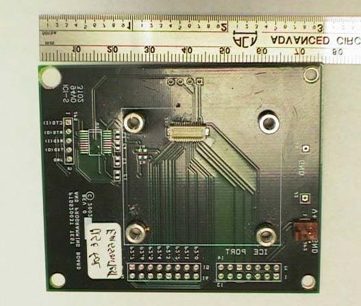
Click to zoom
Application Details
- Equipment Class
- DSS - Part 15 Spread Spectrum Transmitter
- Date of Grant
- Feb 28, 2003
- Application Purpose
- Original Equipment
- Date of Application
- Feb 28, 2003
- Equipment Note
- PTSS2003 Spread Spectrum
- Frequency Range
- 903.00000000 - 927.00000000
- Company
- Elkhart Brass Mfg Co Inc
- Country
- United States
Documents & Files
Document Text
Text extracted from the exhibit documents filed with the FCC. Open a document above to read the original.
Users Manual
FCC ID: QT8PTSS2003 Elkhart Brass Mfg. Co., Ltd. PTSS2003Transceiver Users Manual (Preliminary) RF Transceiver Installation Instructions The PTSS2003 Transceiver Frequency Hopping Spread Spectrum transceiver. This transceiver should only be installed by qualified service personnel. The transceiver detects level, low battery or other data signals from the external binary inputs and broadcasts that data to the system's host receiver. MOUNTING LOCATION The PTSS2003 Transceiver is a module as defined by the FCC and therefore must be mounted to another host device in order to function. This device is intended only for OEM integrators under the following conditions: 1) The integrator must position this device in any end product such that the antenna to user/bystander distance is greater than 20 cm when the transmitter is functioning (excluding hands, wrists, feet and ankles). 2) The transmitter module may not be co-located with any other transmitter or antenna. As long as the 2 conditions above are met, further transmitter testing will not be required. However, the OEM integrator is still responsible for testing their end-product for any additional compliance requirements required with this module installed (for example, digital device emissions, PC peripheral requirements, etc.). IMPORTANT NOTE: In the event that these conditions can not be met (for example applications where the antenna to user distance is < 20 cm or to be co-located with another transmitter), then the original FCC authorization is no longer considered valid and the FCC ID can not be used on the final product. In these circumstances, the OEM integrator will be responsible for re-evaluating the end product (including the transmitter) and obtaining a separate FCC authorization. NOTICE TO CUSTOMER Any Elkhart Brass Mfg. Co., Ltd. customer incorporating the PTSS2003 transceiver module into its own product must have an external notice affixed to its product. This notice must be placed in a conspicuous location and can use wording such as: “Contains FCC ID: QT8PTSS2003” or “Contains Transceiver Module FCC ID: QT8PTSS2003”. Any similar wording that expresses the same meaning may be used. NOTE: The end user should NOT be provided any instructions on how to remove or install the device. RF Exposure Manual Information That Must be Included to End User The users manual for end users must include the following information in a prominent location "IMPORTANT NOTE: To comply with FCC RF exposure compliance requirements, the antenna used for this transmitter must be installed to provide a separation distance of at least 20 cm from all persons and must not be co-located or operating in conjunction with any other antenna or transmitter." FCC ID: QT8PTSS2003 INSTALLATION INSTRUCTIONS 1. Supply the transceiver with DC power by inserting a 3.6 Volt battery into the battery holder on the customers host application circuit board. 2. The unit will come pre-programmed with a Network ID and Hop Seed. However, the customer does have the option of field programming the unit. 3. If possible, avoid installing the PTSS2003 in areas near large metallic objects such as air conditioners, heaters, screens and heaters. CAUTION: This device is required to comply with FCC RF exposure requirements for mobile and fixed transmitting devices. The FCC requires that the antenna used for this transmitter must be installed to provide a separation of at least 20 cm (8 inches) from all persons (not including hands, wrists, feet, and ankles) and must not be co-located or operating in conjunction with any other antenna or transmitter. FCC NOTICE The Model PTSS2003 transceiver generates and uses radio frequency energy. If not installed and used in accordance with the manufacturer's instructions, it may cause interference to radio and television reception. The transceiver has been tested and found to comply with the specifications in Part 15 of FCC Rules for Spread Spectrum Intentional Radiators and FCC Part 15 Subpart C, Specifications. If this equipment causes interference to radio or television reception - which can be determined by turning the equipment on and off - the installer is encouraged to correct the interference by one or more of the following measures: 1) Reorient the antenna of the radio/television. 2) Connect the AC transformer to a different outlet so the control panel and radio/television are on different branch circuits. 3) Relocate the control panel with respect to the radio/television. If necessary, the installer should consult an experienced radio/television technician for additional suggestions, or send for the "Interference Handbook" prepared by the Federal Communications Commission. This booklet is available from the U.S. Government Printing Office, Washington, D.C., 20402, stock number 004-000-00450-7. CAUTION: No field changes or modifications to the PTSS2003 should be made unless they are specifically covered in this manual. All adjustments must be made at the factory under the specific guidelines set forth in our manufacturing processes. Any modification to the equipment could void the user's authority to operate the equipment and render the equipment in violation of FCC Part 15, Subpart C, 15.247. This device complies with Part 15 of the FCC Rules. Operation is subject to the following two conditions: (1) this device may not cause harmful interference, and (2) this device must accept any interference received, including interference that may cause undesired operation. LIMITED WARRANTY THERE ARE NOT WARRANTIES, EXPRESS OR IMPLIED, OF MERCHANTABILITY OR FITNESS FOR A PARTICULAR PURPOSE OR OTHERWISE, WHICH EXTEND BEYOND THE DESCRIPTION ON THE FACE HEREOF. In no case shall Seller be liable to anyone for any consequential or incidental damages for breach of this or any other warranty, express or implied, or upon any other basis of liability whatsoever, even if the loss or damage is caused by Seller's own negligence or fault.
Block Diagram
FCC ID: QT8PTSS2003
Cover Letter(s)
FCC ID: QT8PTSS2003
Cover Letter(s)
FCC ID: QT8PTSS2003
Cover Letter(s)
FCC ID: QT8PTSS2003
External Photos
FCC ID: QT8PTSS2003 Photo 1.Top View of Interface Board w/ EUT FCC ID: QT8PTSS2003 Photo 2.Top View of Interface Board FCC ID: QT8PTSS2003 Photo 3.EUT, Top View of TX FCC ID: QT8PTSS2003 Photo 4.EUT, Top View of TX with Shield Removed FCC ID: QT8PTSS2003 Photo 5.EUT, Bottom View of TX FCC ID: QT8PTSS2003 Photo 6.TX Antenna
ID Label/Location Info
FCC ID: QT8PTSS2003
Internal Photos
FCC ID: QT8PTSS2003 Photo 1.Top View of Interface Board w/ EUT FCC ID: QT8PTSS2003 Photo 2.Top View of Interface Board FCC ID: QT8PTSS2003 Photo 3.EUT, Top View of TX FCC ID: QT8PTSS2003 Photo 4.EUT, Top View of TX with Shield Removed FCC ID: QT8PTSS2003 Photo 5.EUT, Bottom View of TX FCC ID: QT8PTSS2003 Photo 6.TX Antenna
Operational Description
FCC ID: QT8PTSS2003 GENERAL INFORMATION 1.1Product Description The Equipment Under test is the Elkhart Brass Mfg. Co., Inc., Model PTSS2003 Spread Spectrum Transceiver Module. The EUT is a Modular frequency hopping spread spectrum data transceiver that operates in the 902 – 928 MHz frequency band. The manufacturer is requesting a modular approval for this device as shown on the following page. The modulation used is binary frequency shift keying with a deviation of 100 kHz. The RF data rate is 76.8 kbps.
RF Exposure Info
FCC ID: QT8PTSS2003 6.1 RF Safety Requirements to 2.1091 for Mobile Transmitters Power Output The EUT’s maximum expected output power is shown in section 2.7 is Frequency of Fundamental (MHz) Measurement (Watt)* Antenna Gain (dBi) P ERP (Watt) 915.00.23280.00.2328 Source Based Time Averaging Additionally, source based time averaging may be applied as the worse case duty cycle is given as follows: Worse Case Duty Cycle: There is a ‘supervisory delay’ between the end of one message burst and the beginning of the next message. The supervisory delay is 1.5 times the last transmission with a maximum per transmission of 40 ms. Duty cycle = (on time)/(total time) = 40/100 = 40 % This yields for a duty cycle correction of 10 log (0.40) = -4.0 dB Therefore the maximum EIRP may be expected to be 10 log (232.8 mW) = +23.7 dBm 23.7 dBm – 4.0 dB = +19.7 dBm Antilog(19.7 dBm/10) = 93.3 mW FCC ID: QT8PTSS2003 MPE Calculations The limits for this unit (uncontrolled exposure) are 0.61 mW/cm 2 for 915 MHz. Taking the RF Denisty Field Equation: S = (EIRP in mW)/(4πR 2 ) and solving for Distance R R = SQRT (EIRP in mW)/(S4π) Solving the above equation yields R (cm) = SQRT (93.3(mw))/(0.61(mW/cm 2 )*4*π) = 3.5 cm Since the EUT is designed only for mobile applications (where the expected separation distance between antenna and humans is greater than 20 cm), all manual instructions have specified 20 cm as the minimum exposure distance.
Test Report
Elkhart Brass Mfg. Co., Inc. FCC Part 15, Certification Application PTSS2003 Spread Spectrum Transceiver Module February 10, 2003 MEASUREMENT/TECHNICAL REPORT COMPANY NAME:Elkhart Brass Mfg. Co., Inc. MODEL:PTSS2003 Spread Spectrum Transceiver Module FCC ID:QT8PTSS2003 DATE:February 10, 2003 This report concerns (check one): Original grant X Class II change_____ Equipment type: Spread Spectrum Transceiver Deferred grant requested per 47 CFR 0.457(d)(1)(ii)? yes_____ No X If yes, defer until:_________________ date N.A. agrees to notify the Commission by N.A. date of the intended date of announcement of the product so that the grant can be issued on that date. Report prepared by: United States Technologies, Inc. 3505 Francis Circle Alpharetta, GA 30004 Phone Number: (770) 740-0717 Fax Number: (770) 740-1508 FCC ID: QT8PTSS2003 TABLE OF CONTENTS AGENCY AGREEMENT LETTER OF CONFIDENTIALITY SECTION 1 GENERAL INFORMATION 1.1 Product Description 1.2 Related Submittal(s) SECTION 2 TESTS AND MEASUREMENTS 2.1 Configuration of Tested EUT 2.2 Test Facility 2.3 Test Equipment 2.4 Modifications 2.5 Test Procedure and Results 2.6 Antenna Description 2.7 Peak Power (Antenna Conducted at Antenna Terminal) 2.8 Antenna Conducted Spurious Emissions 2.9 Peak Radiated Spurious Emissions 2.10 Average Radiated Spurious Emissions 2.11 Minimum 20 dB Bandwidth 2.12 Number of Hopping Channels 2.13 Average Time of Occupancy per Channel 2.14 Power Line Conducted Emissions for Transmitter 2.15 Radiated Emissions for Digital Device & Receiver (if Applicable) 2.16 Power Line Conducted for Digital Device & Receiver (if Applicable) SECTION 3 LABELING INFORMATION SECTION 4 BLOCK DIAGRAM(S)/ SCHEMATIC(S) SECTION 5 PHOTOGRAPHS SECTION 6 RF EXPOSURE INFORMATION SECTION 7 THEORY OF OPERATION SECTION 8 USER'S MANUAL FCC ID: QT8PTSS2003 SECTION 1 GENERAL INFORMATION FCC ID: QT8PTSS2003 GENERAL INFORMATION 1.1Product Description The Equipment Under test is the Elkhart Brass Mfg. Co., Inc., Model PTSS2003 Spread Spectrum Transceiver Module. The EUT is a Modular frequency hopping spread spectrum data transceiver that operates in the 902 – 928 MHz frequency band. The manufacturer is requesting a modular approval for this device as shown on the following page. The modulation used is binary frequency shift keying with a deviation of 100 kHz. The RF data rate is 76.8 kbps. FCC ID: QT8PTSS2003 FCC ID: QT8PTSS2003 1.2Related Submittal(s)/Grant(s) The EUT will be used with part of a system to send/receive data. The transceiver presented in this report will be used with other like transmitters The EUT is subject to the following authorizations: a) Certification as a transceiver b) Verification as a receiver and digital device The information contained in this report is presented for the certification & verification authorization(s) for the EUT. FCC ID: QT8PTSS2003 SECTION 2 TESTS AND MEASUREMENTS FCC ID: QT8PTSS2003 TEST AND MEASUREMENTS 2.1 Configuration of Tested System The sample was tested per ANSI C63.4, Methods of Measurement from Low-Voltage Electrical and Electronic Equipment in the Range of 9 kHz to 40 GHz (1992). Conducted and radiated emissions data were taken with the test receiver or spectrum analyzer's resolution bandwidth adjusted to 9 kHz and 120 kHz, respectively. All measurements are peak unless stated otherwise. The video filter associated with the spectrum analyzer was off throughout the evaluation process. Interconnecting cables were manipulated as necessary to maximize emissions. Interconnecting cables were manipulated as necessary to maximize emissions. A block diagram of the tested system is shown in Figure 1. Test configuration photographs for spurious and fundamental emissions are shown in Figure 2. The sample used for testing was received by U.S. Technologies on January 2, 2003 in good condition. 2.2 Test Facility Testing was performed at US Tech's measurement facility at 3505 Francis Circle, Alpharetta, GA. This site has been fully described and submitted to the FCC, and accepted in their letter marked 31040/SIT. Additionally this site has also been fully described and submitted to Industry Canada (IC), and has been approved under file number IC2982. 2.3 Test Equipment Table 2 describes test equipment used to evaluate this product. 2.4 Modifications No modifications were made by US Tech, to bring the EUT into compliance with FCC Part 15, Limits for the transmitter portion of the EUT or the Class B Digital Device Requirements. FCC ID: QT8PTSS2003 4” S to Monopole Antenna 8" U FIGURE 1a TEST CONFIGURATION (Radiated Emissions) Transceiver (EUT) Batteries FCC ID: QT8PTSS2003 4” S to Monopole Antenna 6’ U FIGURE 1b TEST CONFIGURATION (Conducted Emissions) Transceiver (EUT) AC/DC Adapter FCC ID: QT8PTSS2003 Test Date:January 15, 2003 UST Project:03-0020 Customer:Elkhart Brass Mfg. Co., Inc. Model:PTSS2003 Spread Spectrum Transceiver Module FIGURE 2a Photograph(s) for Spurious and Fundamental Emissions Test photographs were found to b corrupted and could not be provided FCC ID: QT8PTSS2003 Test Date:January 15, 2003 UST Project:03-0020 Customer:Elkhart Brass Mfg. Co., Inc. Model:PTSS2003 Spread Spectrum Transceiver Module FIGURE 2b Photograph(s) for Conducted Emissions FCC ID: QT8PTSS2003 TABLE 1a EUT and Peripherals (Radiated Emissions) PERIPHERAL MANUFACTURER MODEL NUMBERSERIAL NUMBER FCC ID:CABLES P/D Transceiver Module Elkhart Brass Mfg. Co., Inc. (EUT) PTSS200315101, 15102QT8PTSS2003 (Pending) 4” S to Monopole Antenna Monopole Antenna Linx ANT-915-CW-QW NoneN/A BatteryNoneNoneN/A8" U FCC ID: QT8PTSS2003 TABLE 1b EUT and Peripherals (Conducted Emissions) PERIPHERAL MANUFACTURER MODEL NUMBER SERIAL NUMBER FCC ID:CABLES P/D Transceiver Module Elkhart Brass Mfg. Co., Inc. (EUT) PTSS200315101, 15102QT8PTSS2003 (Pending) 4” S to Monopole Antenna Monopole Antenna Linx ANT-915-CW- QW NoneN/A AC/DC AdapterAC-E344A97J I4N/A6’ U FCC ID: QT8PTSS2003 TABLE 2 TEST INSTRUMENTS TYPEMANUFACTURERMODELSN. SPECTRUM ANALYZERHEWLETT-PAC…
Text truncated - open the document above for the full version.
Test Setup Photos
FCC ID: QT8PTSS2003 Test Date:January 15, 2003 UST Project:03-0020 Customer:Elkhart Brass Mfg. Co., Inc. Model:PTSS2003 Spread Spectrum Transceiver Module FIGURE 2a Photograph(s) for Spurious and Fundamental Emissions FCC ID: QT8PTSS2003 Test Date:January 15, 2003 UST Project:03-0020 Customer:Elkhart Brass Mfg. Co., Inc. Model:PTSS2003 Spread Spectrum Transceiver Module FIGURE 2b Photograph(s) for Conducted Emissions
Contact Information
Applicant
Garry Adam Lund(Electrical Design Engineer)
Technical Contact
U.S. Technologies-ConsultantTimothy R Johnson
[email protected]770-740-0717
3505 Francis Circle · Alpharetta, Georgia · United States
Test Firm
US TechSandy McEnery
Technical Specifications
| # | Rule Parts | Frequency Range | Power Output |
|---|---|---|---|
| 1 | 15C | 903 MHz - 927 MHz | 232.00 mW |
Other Applications from Elkhart Brass Mfg Co Inc
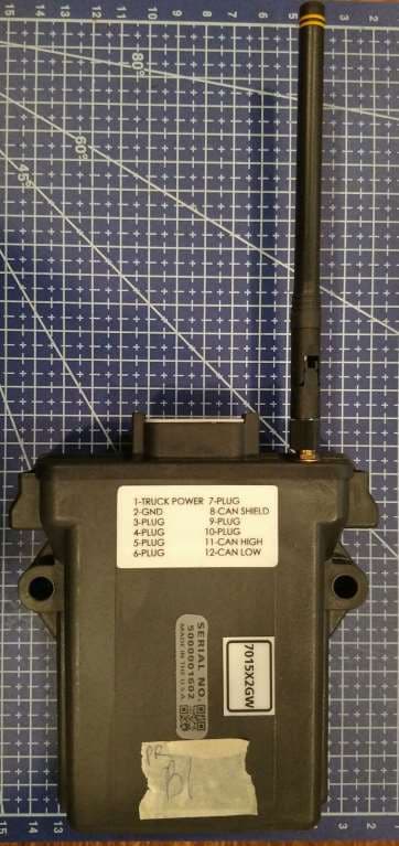
QT8EXM2GW
Jun 16, 2020Gateway to CAN control
Equipment Class
DSS - Part 15 Spread Spectrum Transmitter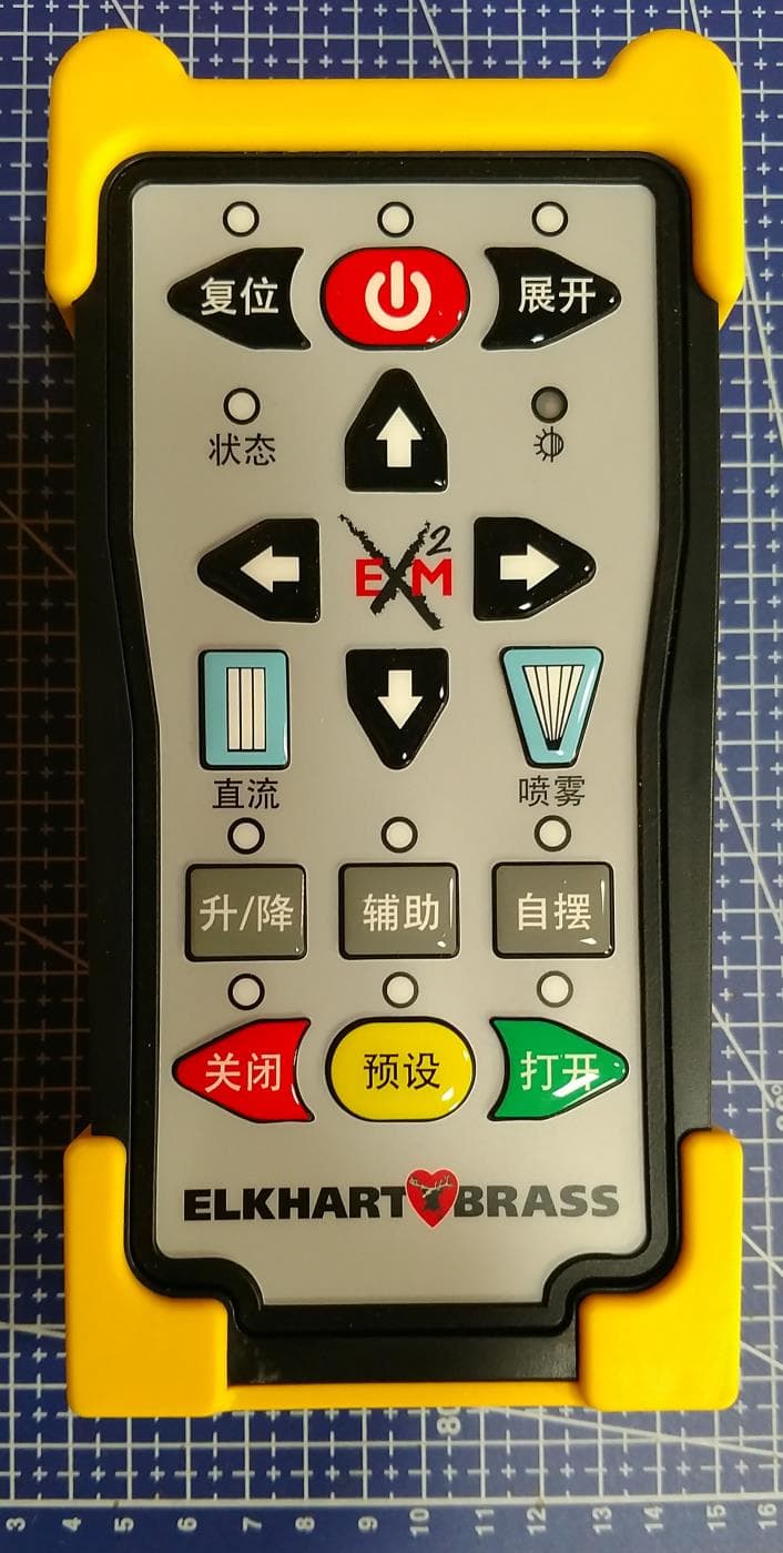
QT8EXM2WH
Apr 20, 2020Wireless Handheld Remote Control
Equipment Class
DSS - Part 15 Spread Spectrum Transmitter