QTG-ZKUSBluetooth Keyboard
ZAGG Inc.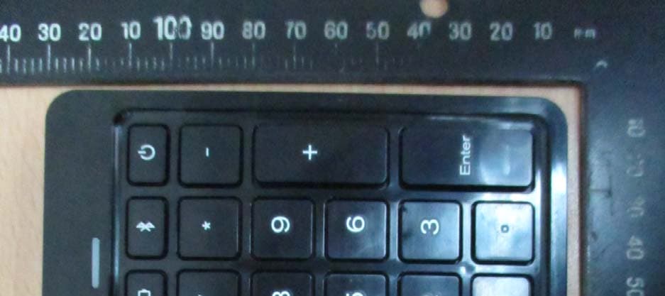
Click to zoom
Application Details
- Equipment Class
- DSS - Part 15 Spread Spectrum Transmitter
- Date of Grant
- Sep 28, 2014
- Application Purpose
- Original Equipment
- Date of Application
- Sep 25, 2014
- Equipment Note
- Bluetooth Keyboard
- Frequency Range
- 2402.00000000 - 2480.00000000
- Company
- ZAGG Inc.
- Country
- United States
Documents & Files
Document Text
Text extracted from the exhibit documents filed with the FCC. Open a document above to read the original.
Users Manual
FRONT Keyboard Instructions 10 Key *WARRANTY REGISTRATION Your ZAGG® 10 Key comes with a one-year manufacturer’s warranty. In order to activate the warranty, you must register your 10 Key as well as keep your purchase receipt. If you purchased your ZAGG 10 Key from ZAGG.com, ZAGG has already registered it and has a copy of your proof of purchase NEED MORE HELP? PLEASE SEE OUR FAQ SECTION AT: www.ZAGG.com/faq See the important Health and Safety information on page 7 before using this product. PAGE 1 POWERING ON AND OFF To turn your 10 Key on, press the Power button. An LED at the top of the 10 Key will light green for two seconds to indicate it has powered on. To turn your 10 Key off, press and hold the Power button for three seconds. A red LED will light and then turn off indicating the power is off. 1 PAIRING YOUR 10 KEY USING YOUR 10 KEY Pairing your 10 Key with your device is easy. It should only need to be paired once, using the following directions. If the connection between your device and 10 Key is ever lost, simply repeat these steps. 1. Access the Bluetooth® settings on your device. 2. On your 10 Key, press and hold the Power button (also the Pair button) for five seconds. A blue LED light at the top of the 10 Key will begin flashing and flash until your 10 Key and device are paired. 3. Your device will display “ZAGG 10 Key” as an available device. Select this option to complete pairing. With your 10 Key paired it’s ready to help you with all your bookkeeping needs. Use it the same way you would a traditional 10 key. Note: The Delete key deletes numbers from right to left. The Clear key deletes complete words or data to the left of your cursor in a document and deletes the contents of an entire cell in a spreadsheet program. PAGE 2 To turn your 10 Key on, press the Power button. An LED at the top of the 10 Key will light green for two seconds to indicate it has powered on. To turn your 10 Key off, press and hold the Power button for three seconds. A red LED will light and then turn off indicating the power is off. 2 CHARGING YOUR 10 KEY Your 10 Key is charged and ready to go right out of the box. When you are ready to recharge your 10 Key, follow these steps: 1. Connect the included micro USB charging cable to the corresponding port on top of the 10 Key. 2. Plug the USB connector into any USB outlet. 3. The LED at the top of the 10 Key will light green and then change to red to indicate it is charging. 4. Wait until the red light turns of, indicating a full charge; it usually takes about three hours to fully charge your 10 Key. 5. Remove the micro USB charging cable and enjoy your 10 Key for up to a year before you need to charge it again. BATTERY LIFE Your 10 Key features a powerful battery that will keep it going for up to a year of regular use between charges*. To check your 10 Key’s remaining battery power, turn it on and then press the Power key again. The LED at the top of the 10 Key will flash one of three ways. 1. Three green flashes indicate 50% or more battery life remaining. 2. Three yellow flashes indicate 26-49% battery life remaining. 3. Three red flashes indicate less than 25% battery life remaining complete pairing. To help preserve battery life, your 10 Key will enter sleep mode if left on and not used for several minutes. To awaken your 10 Key press any key. The 10 Key’s battery has no memory and may be charged whenever you wish. For optimal battery life, we recommend turning your 10 Key off when it will sit unused for a prolonged time. 3 To reach a trained customer service representative, please use one of the following: ZAGG.com/support/contact.php | [email protected] 1-800-700-ZAGG [9244] | 00-1-801-839-3906 for international customers For unparalleled scratch protection for your device, we recommend ZAGG’s InvisibleShield®. ©2005 - 2014 ZAGG Inc All Rights Reserved. PATENT PENDING | NASDAQ: ZAGG | MADE IN CHINA iPad® and Apple® are registered trademarks of Apple, Inc. Bluetooth® is a trademark of Bluetooth SIG, Inc. ZAGG®, InvisibleShield®, and ZAGG Folio™ are trademarks or registered trademarks of ZAGG Inc. Changes or modifications not expressly approved by the party responsible for compliance could void the user’s authority to operate the equipment. This equipment has been tested and found to comply with the limits for a Class B digital device, pursuant to Part 15 of the FCC Rules. These limits are designed to provide reasonable protection against harmful interference in a residential installation. This equipment generates, uses and can radiate radio frequency energy and, if not installed and used in accordance with the instructions, may cause harmful interference to radio communications. However, there is no guarantee that interference will not occur in a particular installation. If this equipment does cause harmful interference to radio or television reception, which can be determined by turning the equipment off and on, the user is encouraged to try to correct the interference by one or more of the following measures: • Reorient or relocate the receiving antenna. • Increase the separation between the equipment and receiver. • Connect the equipment into an outlet on a circuit different from that to which the receiver is connected. • Consult the dealer or an experienced radio/TV technician for help. 4 1. Health Warning: Take frequent breaks when using your keyboard. If you experience any discomfort, pain, tingling, numbness or burning in your neck, shoulders, arms, wrists, hands or any other part of the body, stop using your keyboard and consult a physician. 2. Use only micro-USB chargers in connection with your keyboard. 3. Do not attempt to service your keyboard. 4. Do not disassemble or attempt to disassemble your keyboard. 5. Do not crush or puncture the keyboard. 6. Do not immerse your keyboard in water. 7. Do not put your keyboard in contact with water or other liquids as they could cause a short circuit, fire, or electric shock which could result…
Text truncated - open the document above for the full version.
External Photos
Registration number: W6M21408-14414-FCC FCC ID: QTG-ZKUS Worldwide Testing Services(Taiwan) Co., Ltd. Appendix page 2 of 19 External Photos Registration number: W6M21408-14414-FCC FCC ID: QTG-ZKUS Worldwide Testing Services(Taiwan) Co., Ltd. Appendix page 3 of 19 Registration number: W6M21408-14414-FCC FCC ID: QTG-ZKUS Worldwide Testing Services(Taiwan) Co., Ltd. Appendix page 4 of 19 Registration number: W6M21408-14414-FCC FCC ID: QTG-ZKUS Worldwide Testing Services(Taiwan) Co., Ltd. Appendix page 5 of 19 Registration number: W6M21408-14414-FCC FCC ID: QTG-ZKUS Worldwide Testing Services(Taiwan) Co., Ltd. Appendix page 6 of 19 Registration number: W6M21408-14414-FCC FCC ID: QTG-ZKUS Worldwide Testing Services(Taiwan) Co., Ltd. Appendix page 7 of 19 Registration number: W6M21408-14414-FCC FCC ID: QTG-ZKUS Worldwide Testing Services(Taiwan) Co., Ltd. Appendix page 8 of 19
ID Label/Location Info
A C 3 12 4 2431 A B C D A B D C MT CONFIDENTIAL Sinciya Chen 2014/9/10 Sinciya Chen2014/9/10 A01 MT Lot Control 411MTa~Z () NOTEDATE Cyprus2014/9/10 Sinciya Chen 比例 100% Cradle, , Cyprus A01 5mm 比例 200% 48mm16.4mm 5mm 5mm 48 mm
Internal Photos
Registration number: W6M21408-14414-FCC FCC ID: QTG-ZKUS Worldwide Testing Services(Taiwan) Co., Ltd. Appendix page 9 of 19 Internal Photos Registration number: W6M21408-14414-FCC FCC ID: QTG-ZKUS Worldwide Testing Services(Taiwan) Co., Ltd. Appendix page 10 of 19 Registration number: W6M21408-14414-FCC FCC ID: QTG-ZKUS Worldwide Testing Services(Taiwan) Co., Ltd. Appendix page 11 of 19 Registration number: W6M21408-14414-FCC FCC ID: QTG-ZKUS Worldwide Testing Services(Taiwan) Co., Ltd. Appendix page 12 of 19 Registration number: W6M21408-14414-FCC FCC ID: QTG-ZKUS Worldwide Testing Services(Taiwan) Co., Ltd. Appendix page 13 of 19
Test Report
UCI CENTER FOR RF DESI GN AND CHARACTERIZATION Report for Broadcom By Alfred Grau UCI CENTER FOR RF DESI GN AND CHARACTERIZATION Tested Products.• Antenna 1: integrated antenna. • Frequency = 2.402GHz. • Frequency = 2.441GHz. • Frequency = 2.480GHz. UCI CENTER FOR RF DESI GN AND CHARACTERIZATION Coordinate System Reference: Antenna 1. Top view Side view Z Y X Front view Front viewRear view SMA connector X Z Y UCI CENTER FOR RF DESI GN AND CHARACTERIZATION Radiation pattern: Antenna 1. XZ Plane at f = 2.402GHz Co-cross polarization field (dBi) Solid line: vertical polarizationDash line: horizontal polarization Total field (dBi) 0 45 90 135 180 225 270 315 0 0 -5 -5 -10 -10 -15 -15 -20 -20 -25 -25 -30 -30 -35 0 45 90 135 180 225 270 315 0 0 -5 -5 -10 -10 -15 UCI CENTER FOR RF DESI GN AND CHARACTERIZATION Radiation pattern: Antenna 1. YZ Plane at f = 2.402GHz Co-cross polarization field (dBi) Solid line: vertical polarizationDash line: horizontal polarization Total field (dBi) 0 45 90 135 180 225 270 315 0 0 -5 -5 -10 -10 -15 -15 -20 -20 -25 -25 -30 -30 -35 0 45 90 135 180 225 270 315 0 0 -5 -5 -10 -10 -15 UCI CENTER FOR RF DESI GN AND CHARACTERIZATION Radiation pattern: Antenna 1. XY Plane at f = 2.402GHz Co-cross polarization field (dBi) Solid line: vertical polarizationDash line: horizontal polarization Total field (dBi) 0 45 90 135 180 225 270 315 0 0 -5 -5 -10 -10 -15 -15 -20 -20 -25 -25 -30 -30 -35 0 45 90 135 180 225 270 315 0 0 -5 -5 -10 -10 -15 UCI CENTER FOR RF DESI GN AND CHARACTERIZATION Radiation pattern: Antenna 1. XZ Plane at f = 2.441GHz Co-cross polarization field (dBi) Solid line: vertical polarizationDash line: horizontal polarization Total field (dBi) 0 45 90 135 180 225 270 315 0 0 -5 -5 -10 -10 -15 -15 -20 -20 -25 -25 -30 -30 -35 0 45 90 135 180 225 270 315 0 0 -5 -5 -10 -10 -15 UCI CENTER FOR RF DESI GN AND CHARACTERIZATION Radiation pattern: Antenna 1. YZ Plane at f = 2.441GHz Co-cross polarization field (dBi) Solid line: vertical polarizationDash line: horizontal polarization Total field (dBi) 0 45 90 135 180 225 270 315 0 0 -5 -5 -10 -10 -15 -15 -20 -20 -25 -25 -30 -30 -35 0 45 90 135 180 225 270 315 0 0 -5 -5 -10 -10 -15 UCI CENTER FOR RF DESI GN AND CHARACTERIZATION Radiation pattern: Antenna 1. XY Plane at f = 2.441GHz Co-cross polarization field (dBi) Solid line: vertical polarizationDash line: horizontal polarization Total field (dBi) 0 45 90 135 180 225 270 315 0 0 -5 -5 -10 -10 -15 -15 -20 -20 -25 -25 -30 -30 -35 0 45 90 135 180 225 270 315 0 0 -5 -5 -10 -10 -15 UCI CENTER FOR RF DESI GN AND CHARACTERIZATION Radiation pattern: Antenna 1. XZ Plane at f = 2.480GHz Co-cross polarization field (dBi) Solid line: vertical polarizationDash line: horizontal polarization Total field (dBi) 0 45 90 135 180 225 270 315 0 0 -5 -5 -10 -10 -15 -15 -20 -20 -25 -25 -30 -30 -35 0 45 90 135 180 225 270 315 0 0 -5 -5 -10 -10 -15 UCI CENTER FOR RF DESI GN AND CHARACTERIZATION Radiation pattern: Antenna 1. YZ Plane at f = 2.480GHz Co-cross polarization field (dBi) Solid line: vertical polarizationDash line: horizontal polarization Total field (dBi) 0 45 90 135 180 225 270 315 0 0 -5 -5 -10 -10 -15 -15 -20 -20 -25 -25 -30 -30 -35 0 45 90 135 180 225 270 315 0 0 -5 -5 -10 -10 -15 UCI CENTER FOR RF DESI GN AND CHARACTERIZATION Radiation pattern: Antenna 1. XY Plane at f = 2.480GHz Co-cross polarization field (dBi) Solid line: vertical polarizationDash line: horizontal polarization Total field (dBi) 0 45 90 135 180 225 270 315 0 0 -5 -5 -10 -10 -15 -15 -20 -20 -25 -25 -30 -30 -35 0 45 90 135 180 225 270 315 0 0 -5 -5 -10 -10 -15 UCI CENTER FOR RF DESI GN AND CHARACTERIZATION Return Loss: Antenna 1 BW(-10dB) ¡ 13.48% 2 2.2 2.4 2.6 2.8 3 Frequency (GHz) -16-14-12-10 -8-6-4-2 R e t u r n L o s s ( d B ) UCI CENTER FOR RF DESI GN AND CHARACTERIZATION Measurements summary Frequency (GHz) Plane Return Loss (dB) Polarization Gain max. (dBi) θ for Gain max. φ for Gain max. Antenna 1 2.402 XZ -10.90 Vertical -7.8 290 2.402 XZ -10.90 Horizontal 0.786 182 2.402 YZ -10.90 Vertical 1.21 226 2.402 YZ -10.90 Horizontal -7.75 10 2.402 XY -10.90 Vertical -15.4 20 2.402 XY -10.90 Horizontal 0.93 180 2.441 XZ -12.20 Vertical -7.36 318 2.441 XZ -12.20 Horizontal 1.32 180 2.441 YZ -12.20 Vertical 0.981 204 2.441 YZ -12.20 Horizontal -8.23 24 2.441 XY -12.20 Vertical -14.1 -14 2.441 XY -12.20 Horizontal 1.74 180 2.48 XZ -13.80 Vertical -7.95 312 2.48 XZ -13.80 Horizontal 1.81 186 2.48 YZ -13.80 Vertical 0.204 214 2.48 YZ -13.80 Horizontal -8.38 8 2.48 XY -13.80 Vertical -15.8 12 2.48 XY -13.80 Horizontal 1.87 180
Test Report
of Applicant: ZAGG Inc. Address: 3855 South 500 West, Ste Q Salt Lake City, UT 84115, U.S.A. Tested and Prepared by Worldwide Testing Services (Taiwan) Co., Ltd. FCC Registration No.: 930600 Industry Canada filed test laboratory Reg. No. IC 5679A-1, IC 5107A A2LA Accredited No.: 2732.01 Report No.: W6M21408-14414-C-1 6F, NO. 58, LANE 188, RUEY-KUANG RD., NEIHU TAIPEI 114, TAIWAN, R.O.C. TEL: 886-2-66068877 FAX: 886-2-66068879 E-mail: [email protected] FCC PART 15 SUBPART C TEST REPORT for Bluetooth Keyboard Model No.: ZAGG 10-key FCC ID: QTG-ZKUS Registration number: W6M21408-14414-C-1 FCC ID: QTG-ZKUS Worldwide Testing Services(Taiwan) Co., Ltd. Page 1 of 42 TABLE OF CONTENTS 1 GENERAL INFORMATION ...................................................................................................... 2 1.1 Notes .................................................................................................. 2 1.2 Testing laboratory .................................................................................................. 3 1.2.1 Location .................................................................................................. 3 1.2.2 Details of accreditation status .............................................................................................. 3 1.3 Details of approval holder .................................................................................................. 3 1.4 Application details .................................................................................................. 4 1.5 General information of Test item......................................................................................... 4 1.6 Test standards .................................................................................................. 5 2 TECHNICAL TEST .................................................................................................................... 6 2.1 Summary of test results .................................................................................................. 6 2.2 Test environment .................................................................................................. 6 2.3 Test Equipment List .................................................................................................. 7 2.4 General Test Procedure .................................................................................................. 9 3 TEST RESULTS (ENCLOSURE) ............................................................................................ 11 3.1 Peak Output Power (transmitter) ....................................................................................... 12 3.2 RF Exposure Compliance Requirements ........................................................................... 15 3.3 Out of Band Radiated Emissions ....................................................................................... 15 3.4 Transmitter Radiated Emissions in restricted Bands ......................................................... 16 3.5 Spurious emissions (tx) ................................................................................................ 17 3.6 Carrier Frequency Separation ............................................................................................ 21 3.7 Number of Hopping Frequencies....................................................................................... 24 3.7.1 Pseudorandom Frequency Hopping Sequence................................................................... 26 3.7.2 Coordination of hopping sequences to other transmitters ................................................. 26 3.7.3 System Receiver Hopping Capability ................................................................................ 26 3.8 Time of Occupancy (Dwell Time) ..................................................................................... 27 3.9 20dB Bandwidth ................................................................................................ 33 3.9.1 System Receiver Input Bandwidth .................................................................................... 35 3.10 Band-edge Compliance of RF Emissions .......................................................................... 36 3.11 Radiated Emissions from Receiver Section of Transceiver............................................... 39 3.12 Power Line Conducted Emission....................................................................................... 40 Appendix Registration number: W6M21408-14414-C-1 FCC ID: QTG-ZKUS Worldwide Testing Services(Taiwan) Co., Ltd. Page 2 of 42 1 General Information 1.1 Notes The purpose of conformity testing is to increase the probability of adherence to the essential requirements or conformity specifications, as appropriate. The complexity of the technical specifications, however, means that full and thorough testing is impractical for both technical and economic reasons. Furthermore, there is no guarantee that a test sample which has passed all the relevant tests conforms to a specification. Neither is there any guarantee that such a test sample will interwork with other genuinely open systems. The existence of the tests nevertheless provides the confidence that the test sample possesses the qualities as maintained and that is performance generally conforms to representative cases of communications equipment. The test results of this test report relate exclusively to the item tested as specified in 1.5. The test report may only be reproduced or published in full. Reproduction or publication of extracts from the report requires the prior written approval of the Worldwide Testing Services(Taiwan) Co., Ltd. Tester: September 16, 2014 Mark Cheng Date WTS-Lab. Name Signature Technical responsibility for area of testing: September 16, 2014 Kevin Wang Date WTS Name Signature Registration number: W6M21408-14414-C-1 FCC ID: QTG-ZKUS Worldwide Testing Services(Taiwan) Co., Ltd. Page 3 o…
Text truncated - open the document above for the full version.
Test Setup Photos
Registration number: W6M21408-14414-FCC FCC ID: QTG-ZKUS Worldwide Testing Services(Taiwan) Co., Ltd. Appendix page 14 of 19 Set Up Photo of Radiated Emission EMI Battery Below 1GHz Registration number: W6M21408-14414-FCC FCC ID: QTG-ZKUS Worldwide Testing Services(Taiwan) Co., Ltd. Appendix page 15 of 19 Above 1GHz Registration number: W6M21408-14414-FCC FCC ID: QTG-ZKUS Worldwide Testing Services(Taiwan) Co., Ltd. Appendix page 16 of 19 Charge Below 1GHz Registration number: W6M21408-14414-FCC FCC ID: QTG-ZKUS Worldwide Testing Services(Taiwan) Co., Ltd. Appendix page 17 of 19 Above 1GHz Registration number: W6M21408-14414-FCC FCC ID: QTG-ZKUS Worldwide Testing Services(Taiwan) Co., Ltd. Appendix page 18 of 19 RF Registration number: W6M21408-14414-FCC FCC ID: QTG-ZKUS Worldwide Testing Services(Taiwan) Co., Ltd. Appendix page 19 of 19 Set Up Photo of Conducted Emission
Contact Information
Applicant
Dan Oakeson(Director of Product Development)
Technical Contact
Worldwide Testing Services (Taiwan) Co., Ltd.Tse-Ming Chang
[email protected]886-2-6606-8877
6F., No.58, Lane 188, Ruey Kuand Rd., · Taiwan
Non-Technical Contact
Worldwide Testing Services (Taiwan) Co., Ltd.Ivy Lin
[email protected]886-2-6606-8877
Test Firm
Worldwide Testing Services (Taiwan) Co., Ltd.Rex Kao
Technical Specifications
| # | Rule Parts | Frequency Range | Power Output |
|---|---|---|---|
| 1 | 15C | 2.40 GHz - 2.48 GHz | 400.00 µW |
Other Applications from ZAGG Inc.

QTG-ZKPXN
Jul 23, 2026Bluetooth Keyboard
Equipment Class
DTS - Digital Transmission System
QTG-ZWSAPUNI58-2
Sep 10, 2024Pro stylus 2
Equipment Class
DTS - Digital Transmission System
QTG-ZKPIB13
Sep 04, 2024Pro Keys 2
Equipment Class
DTS - Digital Transmission System
QTG-ZWCIHSTK
Jul 21, 2024Magnetic Wireless Charger
Equipment Class
DCD - Part 15 Low Power Transmitter Below 1705 kHz
QTG-ZMIHSTK
Jul 13, 2024Mouse
Equipment Class
DTS - Digital Transmission System