QTYJMAMARK002J.M.A. Computer & Wireless Auto Measuring System
James Mason Australia P/L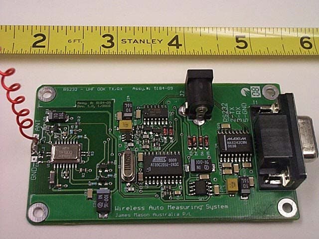
Click to zoom
Application Details
- Equipment Class
- DXT - Part 15 Low Power Transceiver, Rx Verified
- Date of Grant
- May 15, 2003
- Application Purpose
- Original Equipment
- Date of Application
- Mar 28, 2003
- Equipment Note
- J.M.A. Computer & Wireless Auto Measuring System
- Frequency Range
- 916.00000000 - 916.00000000
- Company
- James Mason Australia P/L
- Country
- Australia
Documents & Files
Document Text
Text extracted from the exhibit documents filed with the FCC. Open a document above to read the original.
Block Diagram
International Certification Services, Inc. James Mason Model: J.M.A. Computer & Wireless Auto Measuring System System Block Diagram Transmitter Box Computer TRAM LCD Display Push Button Transmit Switches International Certification Services, Inc. TRANSMITTER BOX BLOCK DIAGRAM RF Transceiver Chip Internal Wire Antenna UP Chip To Serial Port on Computer International Certification Services, Inc. TRAM SYSTEM BLOCK DIAGRAM uP RF Interface and LCD Display Interface uP LCD (#2) Display Interface LCD #1 LCD #2 RF Transceiver Chip Internal Wire Antenna
Internal Photos
1100 Falcon Ave. Tele:320-864-4444 Glencoe, MN 55336 Fax: 320-864-6611 “Your Agent to Product Certifications and Licenses Throughout the World” James Mason Australia P/L March 26, 2003 Product: J.M.A.Computer & Wireless Auto Measuring System INTERNAL PHOTOS PC Transceiver showing Component side of the PC Board INTERNATIONAL CERTIFICATION SERVICES INC. Fixed Internal Wire Antenna Serial Port Connection to Computer DC Power Connection International Certification Services, Inc. [email protected] Final Product (PC Transceiver Computer Interface) with Bottom panel removed International Certification Services, Inc. [email protected] TRAM ASSEMBLY RF Transceiver board Internal Wire Antenna UP board interface to RF and to LCD Displays uP board Interface to LCD Display #2 LCD #2 LCD #1 International Certification Services, Inc. [email protected] TRAM RF TRANSCEIVER PC BOARD Component Side Solder Side International Certification Services, Inc. [email protected] TRAM PC BOARDS COMPONENT SIDE International Certification Services, Inc. [email protected] TRAM PC BOARDS SOLDER SIDE
Operational Description
1100 Falcon Ave. Tele:320-864-4444 Glencoe, MN 55336 Fax: 320-864-6611 “Your Agent to Product Certifications and Licenses Throughout the World” To: FCC March 26, 2003 From: Duane R. Bagdons James Mason product Model: J.M.A. Computer & Wireless Auto Measuring System OPERATION DESCRIPTION: This device consists of two parts: 1) TRAM assembly, and 2) Transmitter box attached to a computer. The function of this device is to compare dimensions of a vehicle from after a vehicle repair to the original dimensions from the factory. This device (TRAM) is placed on the repaired vehicle and when desired, a push button switch on the TRAM part of the device is pressed and this transmits measured data from the TRAM to the identical transceiver in the Transmitter box which is connected to the computer. This information is then recorded in the computer. Both ends of the device (TRAM and Transmitter box) contain identical transmitter and receiver units. The device operates on the frequency of 916 Mhz and is pulse modulated. The maximum length of a transmitted burst is 190 mS. A typical message is considerably shorter. During periods of no activity, the communication is constantly looking for a complete communication circuit by polling with ACK’s , NAK’s which are 20 mS bursts of signal. A poll message is sent from the PC side (Transmitter box). If the remote unit (TRAM) has anything to transmit (New measurement), a data message is transmitted back. If there are no new measurements, the remote unit will not reply. ACK or NAK messages are sent in reply to data messages. Microprocessors, on both sides, control the data transmission. A Data buffer in the microprocessor (internal RAM) holds the message data. All messages are fixed length. There are two modes of operation for the system: • Idle mode - No radio transmissions, so we can ignore this mode of operation. • Recording mode - In the recording mode, system is transmitting "data messages" (all data messages are always 190ms) and "control messages" (all control messages POLL and ACK are always 20ms). The length of these messages is controlled by micro FW on both sides (PC and black box side). There are three possible situations in the recording mode: • PC side needs to send data to the black box (operator is starting or stopping the recording mode of operation). In this situation, instead of sending a regular POLL control message, PC side sends a data message (190ms) to the black box. If this message is received by the black box, it will reply with ACK control message. When PC side receives this ACK control message, this instance of data transfer from PC to the black box is completed and regular POLL control messages will resume, but only after another 800ms delay. • Black box needs to send data to the PC (operator has pressed transmit button on the black box). Black box will wait for the POLL control message from the PC side. When this POLL control message is received, black box will send back the data message (190ms). Upon receiving this data message, PC side will send back ACK control message to the black box. This completes the data transfer from black box to the PC side. The next POLL control message from the PC side will be sent after the 800ms delay. INTERNATIONAL CERTIFICATION SERVICES INC. International Certification Services, Inc. [email protected] * Neither PC nor black box side needs to transfer data - PC side is sending POLL control messages every 800ms. Black box will not reply to these messages. The situation where our system will transmit the most messages is case 2 where black box needs to transfer data to the PC side. Our system will transmit POLL control message (20ms - sent by PC side), immediately followed by data message (190ms – send by black box), immediately followed by ACK control message (20ms – sent by PC side). This means the system will transmit for 240ms, followed by 800ms delay.
Schematics
1 1 2 2 3 3 4 4 5 5 6 6 7 7 8 8 AA BB CC DD EE FF ScaleSheet SizeFCSM No.DWG No.Rev 1 of 1 A2 5112-06 1.3 RBO DIGIDATA VEHICLE MEASUREMENT SYSTEM - UHF RADIO - RS232 INTERFACE MODULE SCHEMATIC. REVISIONS: NIL Notes: 1. . 2. . 0V 0V 0V +5V(1) +5V(1) 0V 0V +5V(1) 0V +5V(1) R14 1K R15 10K C6 100N R19 1K C8 100P R16 1K C7 100P C11 100N C12 1U0 C9 33pF C10 33pF X1 11.0592MHz P1-7 19 A0P1-0 12 A1P1-1 13 P1-2 14 P1-3 15 P1-4 16 P1-5 17 P3-0RX 2 P3-1TX 3 P3-6 11 P1-6 18 P3-2I0 6 P3-3I1 7 P3-5T1 9 P3-4T0 8 OSC1 5 OSC2 4 VCC 20 GND 10 RST 1 U3 AT89C2051-2 TX-RADIO TX-MICRO RX-MICRO 8 9 10 U2C 74HC32 11 12 13 U2D 74HC32 6 4 5 U2B 74HC32 3 1 2 U2A 74HC32 D1 LS4148 D2 LS4148 R20 10K R17 10K +5V(1) Q4 FDV301N L5 47UH C20 100NF 0V R4 27K R8 47K R11 100R R10 10K R3 100K R2 30K R9 10K R12 10K R7 470K R6 330K R5270K C1 2200PF C2 15NF C4 4N7 L2 56nH 0V 0V 0V L3 100nH 0V 0V 0V C5 10uF VCC 1 AGC CAP PK DET BB OUT 2 3 4 5 6 7 8 9 1011 GND 2 LPF ADJ TX MOD RX DATA CMP IN RREF THLD 2 THLD 1 13 12 14 15 P RATE P WIDTH VCC 2 CNT RL1 17 16 18 CNT RLO GND3 19 20 1 GND1RFIO Q1 MMBT2222A Q2 MMBT2222A 0V L1 FAIR-RITE 2506033017YO 0V 0V Q3 FDV301N U1 +3V +3V+3V RX-RADIO +3V C3 ?F R13 1M C1+ 2 V+ 3 C1- 4 C2+ 5 C2- 6 V- 7 T2-OUT 8 R2-IN 9 R2-OUT 10 T2-IN 11 T1-IN 12 R1-OUT 13 R1-IN 14 T1-OUT 15 GND 16 VCC 17 /SHDN 18 /EN 1 U4 MAX202CWE 0V C13 100NF C14 100NF +5V(2) C16 100NF 0V C17 100NF D3 LS4148 D4 LS4148 D5 LS4148 D6 LS4148 0V Vin 8 GND 2 +5V 1 GND 3 GND 6 GND 7 NC 4 NC 5 U5 LM78L05CM C18 100U -16V C19 100NF N.C.N.C. 0V +5V(1)1 2 J2 2 PIN SKT C15 100NF 0V +5V(2) C23 500U-16V 0V L4 100UH C24 10UF C25 100NF C21 10UF C22 100N 0V +5V(2) 0V 1 2 3 4 5 6 7 8 9 J1 9PIN-SKT DB9 Socket NC TX RX NC GND NC NC NC 0V PTT 0V R18 10K Q5 FDV301N +5V(1) Vin 1 N.C 4 ON/OFF 3 Vout 5 GND 2 U6 LP2980 +3V C26 100U -16V C27 100NF NC POWER SUPPLY PC SERIAL PORT 0V C28 100NF +5V(1) 0V Decoupling for U2
Schematics
1 1 2 2 3 3 4 4 5 5 6 6 7 7 8 8 AA BB CC DD EE FF Title NumberRevisionSize B Date:21-Oct-2002Sheet of File:F:\5112\DESIGN\HARDWARE\RADIO\REV1-4\5112-04.SCHDrawn By: R4 27K R12 47K R7 100R R8 10K R3 100K R2 30K R13 10K R9 10K R11 470K R6 330K R5270K C1 2200PF C2 15NF C4 4N7 L2 56nH L3 100nH C5 10uF VCC 1 AGC CAP PK DET BB OUT 2 3 4 5 6 7 8 9 1011 GND 2 LPF ADJ TX MOD RX DATA CMP IN RREF THLD 2 THLD 1 13 12 14 15 P RATE P WIDTH VCC 2 CNT RL1 17 16 18 CNT RLO GND3 19 20 1 GND1RFIO Q3 MMBT2222A Q1 MMBT2222A L1 FAIR-RITE 2506033017YO Q2 FDV301N U1 +3.0V TX-RADIO +3.0V+3.0V RX-RADIO RX-RADIO +3.0V +3.0V C3 ?F R10 1M Radio Board 1.4 5112-04 11 TX-RADIO RX-RADIO PTT-RADIO 1 2 3 4 5 6 7 8 9 10 J1 10X0.5FFC +3V +3V 0V 0V TX 0V PTT 0V RX 0V LK1 R14 8K2 +3.0V Q4 FDV301N For Black Box Radio: - Leave out LK1 and install Q2 R13 For Inner Bar Box Radio: - Leave out Q2 R13 and make LK1
Test Report
TEST REPORT #250303 STANDARD: FCC PART 15 SUBPART C--INTENTIONAL RADIATORS SECTION 15.249 OPERATION WITHIN THE BANDS 902-928 Mhz, 2400-2483.5 Mhz, 5725-5875 Mhz, and 24.0-24.25 Ghz EQUIPMENT TESTED: JAMES MASON AUSTRALIA P/L MODEL: J.M.A.COMPUTER & WIRELESS AUTO MEASURING SYSTEM TEST DATE: 25 MARCH 2003 INTERNATIONAL CERTIFICATION SERVICES, INC. 1100 Falcon Avenue Glencoe, MN 55336 Tele: 320-864-4444 Fax: 320-864-6611 INTERNATIONAL CERTIFICATION SERVICES, INC. Prepared for: Test agent: Test location: Prepared by: . James Mason Australia P/L P.O.Box 81 2 Wellington St Narrabeen NSW 2101 Australia International Certification Services, Inc. 1100 Falcon Avenue Glencoe, MN 55336 Tele: 320-864-4444 Fax: 320-864-6611 International Certification Services, Inc. 1100 Falcon Avenue Glencoe, MN 55336 Tele: 320-864-4444 Fax: 320-864-6611 International Certification Services, Inc. 1100 Falcon Avenue Glencoe, MN 55336 International Certification Services represents to the client that testing is done in accordance with standard procedures applicable and that reported test results are accurate within generally accepted commercial ranges of accuracy. This report only applies to the specific samples tested under stated test conditions. It is the manufacturer’s responsibility to assure that additional production units of this model are manufactured with identical electrical and mechanical components. International Certification Services shall have no liability for any deductions, inferences or generalizations drawn by the client or others from this report. This report is the confidential property of the client. As a mutual protection to our clients, the public and ourselves, extracts from the test report shall not be reproduced except in full without our written approval. INTERNATIONAL CERTIFICATION SERVICES, INC. 1.0 TEST SUMMARY TEST REPORT: #250303 COMPANY: AGENT:International Certification Services, Inc. PHONE:320-864-4444 TEST DATE: EQUIPMENT UNDER TEST: GENERAL TEST SUMMARY: VERIFICATION / CERTIFICATION STATUS: MODIFICATIONS NECESSARY: TESTED BYWRITTEN BY Steve WendlandtDuane R. Bagdons James Mason Australia P/L 25 March, 2003 J.M.A. Computer & Wireless Auto Measuring System The testing was performed at International Certification Services, Inc. at 1100 Falcon Ave, Glencoe, MN 55336 The J.M.A. Computer & Wireless Auto Measuring System was found to be in compliance with the FCC Part 15 Subpart C, Section 15.249 requirements. None INTERNATIONAL CERTIFICATION SERVICES, INC. Applicable Standards 47 CFR Ch.1 (10-1-98 Edition) FCC Part 15Radio Frequency Devices Subpart CIntentional Radiators Section 15.249Operation within the bands 902-928 Mhz, 2400- 2483.5 Mhz, 5725-5875 Mhz and 24.0-24.25 Ghz 2.1Referenced Standards ANSI C63.4-1992Methods of Measurement of Radio-Noise Emissions from Low- Voltage Electrical and Electronic Equipment in the Range of 9 Khz to 40 Ghz. 2.2 Equipment Units Tested The equipment tested is a measuring device to compare vehicle manufacturers data against damaged or repaired vehicles and product a hard copy report of variations at the data reference points of the vehicle. There are three radio transmitters (all identical) in the system. One is for Rod 1 (for reporting the Underbody Measurements), the second is on Rod 2 (for reporting the comparative and Upperbody Measurements), and the third is the transmitter box that connects to the computer for communicating with the above 2 devices. All transmitters operate on the same frequency 916.596 Mhz and are controlled by the device attached to the computer. All receivers are SAW based type devices and do not have a local oscillator. These devices have been verified here at the lab also for radiated emissions and found to be compliant with the 15.109 regulation for Radiated Emission Limits. 2.3 Equipment and Cable Configuration See photos of the EUT PC board and schematic and test configuration setup in Attachment A 2.4 List of Test Equipment Measurement cable losses, and antenna correction factors are included in the Corrected Data column of the data sheet. Quasi Peak Detection was used for measuring the Fundamental frequency signal and Average detection method was used to measure the Harmonics since they were all above 1000 Mhz. The Resolution BW Test Equipment Spectrum Analyzer Preamp Log Periodic Antenna (200-1000 MHz) Horn Antenna (1-18 Ghz) Model Hewlett-Packard 8566B Nextec NB00391 EMCO 3146 EMCO 3115 S/N 2421A00458 378 9101-2991 5697 Last Calibration Date 08/01/02 03/03/03 12/16/02 12/16/02 INTERNATIONAL CERTIFICATION SERVICES, INC. was set at 100 Khz and the Video BW was set at 1 Hz with a Span of 0 Hz to perform the correct average detected measurements. 2.5 Units of Measurement. All measurements were taken in dBuV/m with the antenna located at 3 meters distance from the EUT. Frequency measurements are recorded in Mhz. Input power to the intentional radiator was not recorded---only the radiated emissions with the internal transmitting antenna were recorded. 2.6 Location of Test Site The open area test site (OATS) and conducted measurement facility used to collect the data was International Certification Services, Inc. at 1100 Falcon Ave. in Glencoe, MN 55336. This site has been certified to be in compliance with the normalized site attenuation section of CISPR 16-1. (See FCC Registration number: 91103 and Industry Canada File number: IC 3701.) 2.7 Measurement Procedures The antenna was placed at a distance of 3 meters from the EUT. The EUT was set on an insulating table in the OATS site and rotated through 360 degrees to determine the worst case EUT orientation. The antenna was then positioned vertical and horizontal to determine which antenna polarity orientation was worst case. Then certification data was recorded at all the transmitter frequencies from the fundamental to the 10 th harmonic at an antenna height variation of from 1-4 meters. 2.8Reporting Measurement Data See data sheets and plots in Attachment B for the Transmit…
Text truncated - open the document above for the full version.
Test Setup Photos
1100 Falcon Ave. Tele:320-864-4444 Glencoe, MN 55336 Fax: 320-864-6611 “Your Agent to Product Certifications and Licenses Throughout the World” To: FCC March 28, 2003 From: Duane R. Bagdons Intentional Radiator Test Configuration INTERNATIONAL CERTIFICATION SERVICES INC.
Contact Information
Applicant
James Mason(President)
Test Firm
International Certification Services Inc.Duane Bagdons
Technical Specifications
| # | Rule Parts | Frequency Range | Power Output |
|---|---|---|---|
| 1 | 15C | 916 MHz - 916 MHz | - |