QULBSR3BELSTAR Wireless Information System ( Receiver )
Mitsui & Co., Ltd. Nagoya Office, Machinery Division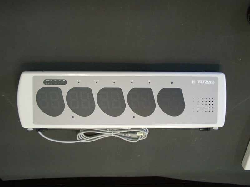
Click to zoom
Application Details
- Equipment Class
- CYY - Communications Receiver used w/Pt 15 Transmitter
- Date of Grant
- Jan 30, 2003
- Application Purpose
- Original Equipment
- Date of Application
- Jan 30, 2003
- Equipment Note
- BELSTAR Wireless Information System ( Receiver )
- Frequency Range
- 298.80000000 - 298.80000000
- Country
- Japan
Documents & Files
Document Text
Text extracted from the exhibit documents filed with the FCC. Open a document above to read the original.
Users Manual
D R A F T D R A F T D R A F T D R A F T 1 11 1 D R A F T 2 22 2 D R A F T Transmitter (Parts names and functions) 1 Transmitter BS-X 2 Call button 3 The transmitter issues a high-pitched tone when the call button is pushed, sending the signal to the receiver. 4 Transmitter BX-3 5 Call button 6 Code number nameplate 7 The last two digits appear on the receiver’s display (set at the factory); these numbers can be changed by the user. 8 Battery lid 9 Open the lid to replace the batteries. 10 Menu stand type 11 Number sticker 12 Menu stand 13 A simple menu can be put here. 14 Napkin stand type 15 Napkins can be inserted here. 16 A menu can be inserted here. 17 Napkin stand 18 <Caution> Napkins and menus cannot be put together. (Where to set) CAUTION! Do not set the transmitter where the ambient temperature exceeds 40°C, humidity is high, or there is water nearby (to prevent corrosion or breakdown). - Set the transmitter away from the wall, metallic surface, or other electric equipment as much as possible (to prevent the deterioration of the radio reception environment). - The transmitter may be damaged if dropped to a hard floor. Keep the transmitter on a secure surface. (How to use) - The transmitter issues a short high-pitched tone when the call button is pushed, sending the signal to the receiver. The receiver, upon receiving the signal, displays the transmitter's registration number in its window--the number first appears in the window on the extreme left, then proceeds toward right as the customers press the call buttons. - The number already in a window begins to flash if the transmitter's call button is pushed again. From left to right, in the order the buttons are pushed. (How to change the registered number) The registered number on the bottom of the transmitter can be changed in the following manner. (1) Open the lid and take out just one battery. (2) Put the battery back while pressing the call button (see the drawing). (3) Remove finger from call button upon hearing the short high-pitched tone. <The following procedures should be carried out as the user watches the receiver.> 3 33 3 D R A F T (4) Press the call button again--the receiver deletes the displayed number and then moves to the registration mode. Shown in the fifth window is the number that is larger than the previously registered number by one. (5) Keep pressing the switch until the desired number is displayed for registration. - Tips - *Numbers appear at a rapid pace when the call button is kept pushed for more than 3 seconds. *Numbers will return to zero after reaching 99. a Numbers displayed in the registration mode b The numeral 1 indicates that the number is being registered. c The transmitter number being registered (6) Move your finger off the call button; the transmitter will issue a short high-pitched tone after 5 seconds, indicating that the registration of the new number is finished. (7) The display on the receiver will disappear 5 seconds after the registration is over. (8) To check if the desired number has been registered, push the call button again and check the displayed number. (9) Put the lid back and screw it on. (The newly registered number differs from the number on the code nameplate. Make the appropriate change.) CAUTION! Do not tighten the screw with too much force, or the screw head will be crushed. (How to change the batteries) - To check the battery, push the call button to hear a short high-pitched tone. If the first tone is followed by another one second later, the battery’s life has run out. - Replace the old batteries with new ones (two size AAA alkali batteries). - Battery have an operating life of about a year. Check them regularly. It is recommended that the batteries of all the transmitters be changed at the same time. Screw Battery lid (1) Unscrew the lid with a Phillips (cross-tipped) screwdriver. (2) Remove the lid and the batteries. (3) Put new batteries in the transmitter (check the polarities). (4) Put the lid back on and tighten the screw (do not screw it with undue force). 4 44 4 D R A F T Number Eraser (Parts names and functions) 1 Eraser switches (5 push buttons) 2 Push the switch corresponding to the display window--the number eraser issues a short high-pitched tone, erasing the number being displayed on the receiver. 3 Push these buttons to change the call receive tone, brightness of the display panel, and the sound volume. 4 Wall hanging hole (two holes) 5 These holes are for hanging the number eraser on the wall. Hook the eraser on the screw heads protruding from the wall. 6 Battery lid 7 Open the lid to change the batteries. 8 Nameplate (Preparation) Read the instructions in "Where to install" below. To hang the number eraser on the wall, put two screws into the wall as shown in the drawing; these screw heads go through the holes on the back of the eraser. Screw interval: 130 mm The two screws must be level with each other. There should be a space of 3 mm between the screw head and the wall surface. Too much space may damage the interior of the number eraser. (Where to install) CAUTION! Do not install the number eraser where the ambient temperature exceeds 40°C, the humidity is high or there is water nearby (to prevent corrosion or breakdown). - Keep the number eraser away from the heat insulated wall covered with aluminum foil, metallic surface, and other electric appliances as much as possible (to prevent the deterioration of the radio reception environment). - The number eraser may be damaged if dropped to a hard floor. Keep it on a secure surface. 5 55 5 D R A F T (How to change the batteries) - To check the battery, push the call button and hear the short high-pitched tone. The battery has run out of life if the first tone is followed by another one second later. - Replace the old batteries with new ones (three size AA alkali batteries). - The battery has an operating life of about a year. (How to use) - Basic operation Push one of these five switches of the number…
Text truncated - open the document above for the full version.
Cover Letter(s)
Date: January 22 nd , 2003 Federal Communications Commission Equipment Approval Services Dear Sir/Madame: Pursuant to Section 0.459 of the Commission’s Rules; Mitsui & Co., Ltd., Nagoya office, Machinery Division hereby request confidentiality as below; 1. Block Diagram The reason of Confidentiality request is that trade secrets and proprietary information are enclosed in the above data, and the public disclosure of the data is harmful for us and will be made unjustifiable benefits to competitors. Sincerely, Signature: Name & Title (printed): Masaki, Takagi, General Manager Section & Company: General Machinery & Systems Department Machinery Division, Nagoya Office, Mitsui & Co., Ltd.
External Photos
External Photo 1: Front View External Photo 2: Rear View External Photo 3: Left Side View External Photo 4: Right Side View External Photo 5: Top View External Photo 6: Bottom View
ID Label/Location Info
FCC ID Label Label Placement (Bottom View)
Internal Photos
Internal Photo 1: Top Cover Removed Internal Photo 2: Receiver Module shield Cover Removed Receiver Module Internal Photo 3: Receiver Module bottom Side Internal Photo 4: Receiver Module Top Side
Test Report
JAPAN QUALITY ASSURANCE ORGANIZATION 21-25, KINUTA 1-CHOME, SETAGAYA-KU, TOKYO 157-8573 JAPAN PHONE (03) 3416-0111, FAX (03) 3416-9691 JQA APPLICATION NO.: 400-20681 Issue Date : January 29, 2003 Page 1 of 25 EMI TEST REPORT JQA APPLICATION NO. : 400-20681 Model No. : BS-R Type of Equipment : Wireless Information System (Receiver) Regulations Applied : CFR 47 FCC Rules and Regulations Part 15 FCC ID : QULBSR3 Applicant : Mitsui & Co., Ltd. Nagoya Office Machinery Division Address : 16-21, Meieki Minami 1-chome, Nakamura-ku, Nagoya-city, Aichi-prefecture 450-8677, Japan Manufacture : Harmony Co., Ltd. Address : 3-62 Sameganji, Jushiyama-mura, Ama-gun, Aichi-prefecture, Japan Received date of EUT : December 26, 2002 Final Judgment : Passed Test results in this report are obtained in use of equipment that is traceable to National Institute of Advanced Industrial Science and Technology (AIST) of Japan and Communication Research Laboratory (CRL) of Japan. The test results only respond to the tested sample. This report should not be reproduced except in full, without the written approval of JQA EMC Engineering Dept. Testing Div. C O P Y JQA Application No. :400-20681 FCC ID :QULBSR3 Model No. :BS-R Issue Date :January 29, 2003 Standard :CFR 47 FCC Rules Part 15 Page 2 of 25 JAPAN QUALITY ASSURANCE ORGANIZATION TABLE OF CONTENTS Page 1 Documentation 1.1 Test Regulation 3 1.2 General Information 3 1.3 Test Condition 4 – 7 1.4 EUT Modifications / Deviation from Standard 8 1.5 Test results / Uncertainty 9 1.6 Summary 10 1.7 Test Configuration / Operation of EUT 11 1.8 EUT Arrangement (Drawings) 12 1.9 Preliminary Test and Test-setup (Drawings) 13 – 16 1.10 EUT Arrangement (Photographs) 17 - 19 2 Test Data 2.1 AC Power Line Conducted Emission 20 - 21 2.2 Radiated Emission (Electric Field) 22 – 23 2.3 Antenna Conducted Power 24 - 25 C O P Y JQA Application No. :400-20681 FCC ID :QULBSR3 Model No. :BS-R Issue Date :January 29, 2003 Standard :CFR 47 FCC Rules Part 15 Page 3 of 25 JAPAN QUALITY ASSURANCE ORGANIZATION 1 DOCUMENTATION 1.1 TEST REGULATION FCC Rules and Regulations Part 15 Subpart A and B (June 23, 1989) All other receivers subject to part 15 Test procedure : AC power line conducted emission, radiated emission and antenna conducted power tests were performed according to the procedures in ANSI C63.4-1992. 1.2 GENERAL INFORMATION 1.2.1 Test facility : 1) Test Facility located at EMC Engineering Dept. Testing Div. : - No.2 and 3 Anechoic Chambers( 3 meters Site ). - Shielded Enclosure. Expiration date of FCC test facility filing : May 27, 2005 2) EMC Engineering Dept. Testing Div. is recognized under the National Voluntary Laboratory accreditation Program for satisfactory compliance established in title 15, Part 285 Code of Federal Regulations. NVLAP Lab Code : 200189-0 (Effective through : June 30, 2003) 1.2.2 Description of the Equipment Under Test (EUT) : 1) Type of Equipment : Wireless Information System (Receiver) 2) Product Type : Production 3) Category : All other receivers subject to part 15 4) EUT Authorization : Certification 5) FCC ID : QULBSR3 6) Trade Name : BELSTAR 7) Model No. : BS-R 8) Tuning Frequency Range : 298.8 MHz 9) Highest Frequency Used in the EUT : 309.5 MHz 10) Serial No. : 02050071 11) Date of Manufacture : None 12) Power Rating : 120 VAC 60 Hz 13) EUT Grounding : None 1.2.3 Definitions for symbols used in this test report : x - indicates that the listed condition, standard or equipment is applicable for this report. - indicates that the listed condition, standard or equipment is not applicable for this report. C O P Y JQA Application No. :400-20681 FCC ID :QULBSR3 Model No. :BS-R Issue Date :January 29, 2003 Standard :CFR 47 FCC Rules Part 15 Page 4 of 25 JAPAN QUALITY ASSURANCE ORGANIZATION 1.3 TEST CONDITION 1.3.1 The measurement of the AC Power Line Conducted Emission x - was performed in the following test site. - was not applicable. Test location : Safety & EMC Center EMC Engineering Dept. Testing Div. 21-25, Kinuta 1-chome, Setagaya-ku, Tokyo 157-8573, Japan x - Shielded Enclosure - Anechoic Chamber No. 2 (portable Type) Used test instruments : Type Model No. Manufacturer Serial No. Last Cal. Interval x - Test Receiver ESH-2 Rohde & Schwarz 880370/016 May 2002 1 Year - Test Receiver ESH-3 Rohde & Schwarz 881460/030 May 2002 1 Year - Test Receiver ESHS10 Rohde & Schwarz 835871/004 May 2002 1 Year - LISN(for Peripheral) KNW-407 Kyoritsu Electrical 8-833-6 Apr. 2002 1 Year x - LISN(for EUT) KNW-407 Kyoritsu Electrical 8-855-2 Apr. 2002 1 Year - LISN KNW-407 Kyoritsu Electrical 8-757-1 Apr. 2002 1 Year x - RF Cable 3D-2W Fujikura 155-21-006E0 Apr. 2002 1 Year - RF Cable 3D-2W Fujikura 155-21-007E0 Apr. 2002 1 Year - 50ohm Termination - SUHNER 154-06-501E0 Jan. 2003 1 Year - 50ohm Termination - SUHNER 154-06-502E0 Jan. 2003 1 Year C O P Y JQA Application No. :400-20681 FCC ID :QULBSR3 Model No. :BS-R Issue Date :January 29, 2003 Standard :CFR 47 FCC Rules Part 15 Page 5 of 25 JAPAN QUALITY ASSURANCE ORGANIZATION 1.3.2 The measurement of the Radiated Emission(30 MHz – 1000 MHz) x - was performed in the following test site. - was not applicable. Test location : Safety & EMC Center EMC Engineering Dept. Testing Div. 21-25, Kinuta 1-chome, Setagaya-ku, Tokyo 157-8573, Japan x - Anechoic Chamber No. 2 (3 meters) - Anechoic Chamber No. 3 (3 meters) Validation of Site Attenuation : 1) Last Confirmed Date :March, 2002 2) Interval :1 year Used test instruments : Type Model No. Manufacturer Serial No. Last Cal. Interval - Spectrum Analyzer 8560E Hewlett Packard 3240A00189 Oct. 2002 1 Year - Spectrum Analyzer 8566B Hewlett Packard 2140A01091 Oct. 2002 1 Year - RF Pre-selector 85685A Hewlett Packard 2648A00522 Oct. 2002 1 Year - Spectrum Analyzer 8566B Hewlett Packard 2747A05855 Apr. 2002 1 Year - RF Pre-selector 85685A Hewlett Packard 2091A00933 Apr. 2002 1 Year - Test Receiver ESV Rohde & Schwarz 872148/039 May 2002 1 Year x - Test Receiver ESVS10 Rohde & Schwarz 826148/0…
Text truncated - open the document above for the full version.
Test Setup Photos
JQA Application No. :400-20681 FCC ID :QULBSR3 Model No. :BS-R Issue Date :January 29, 2003 Standard :CFR 47 FCC Rules Part 15 Page 17 of 25 JAPAN QUALITY ASSURANCE ORGANIZATION 1.10 TEST ARRANGEMENT (PHOTOGRAPHS) PHOTOGRAPHS OF EUT CONFIGURATION FOR AC POWER LINE CONDUCTED EMISSIONS MEASUREMENT Photograph present configuration with maximum emission - Front View – - Side View – C O P Y JQA Application No. :400-20681 FCC ID :QULBSR3 Model No. :BS-R Issue Date :January 29, 2003 Standard :CFR 47 FCC Rules Part 15 Page 18 of 25 JAPAN QUALITY ASSURANCE ORGANIZATION PHOTOGRAPHS OF EUT CONFIGURATION FOR RADIATED EMISSIONS MEASUREMENT Photograph present configuration with maximum emission C O P Y JQA Application No. :400-20681 FCC ID :QULBSR3 Model No. :BS-R Issue Date :January 29, 2003 Standard :CFR 47 FCC Rules Part 15 Page 19 of 25 JAPAN QUALITY ASSURANCE ORGANIZATION C O P Y
Contact Information
Applicant
Mitsuo Shibata(Manager)
Test Firm
Japan Quality Assurance Org.Tetsuo Kato
Technical Specifications
| # | Rule Parts | Frequency Range | Power Output |
|---|---|---|---|
| 1 | 15B | 298.8 MHz - 298.8 MHz | - |
Other Applications from Mitsui & Co., Ltd. Nagoya Office, Machinery Division
QULBSX3
Jan 30, 2003BELSTAR Wireless Information System(Transmitter)
Equipment Class
DSC - Part 15 Security/Remote Control Transmitter
QULBSE3
Jan 30, 2003BELSTAR Wireless Information System (Transmitter)
Equipment Class
DSC - Part 15 Security/Remote Control Transmitter