QVA-SORADIOConnect Radio Module (BLE-LoRa)
SORHEA Inc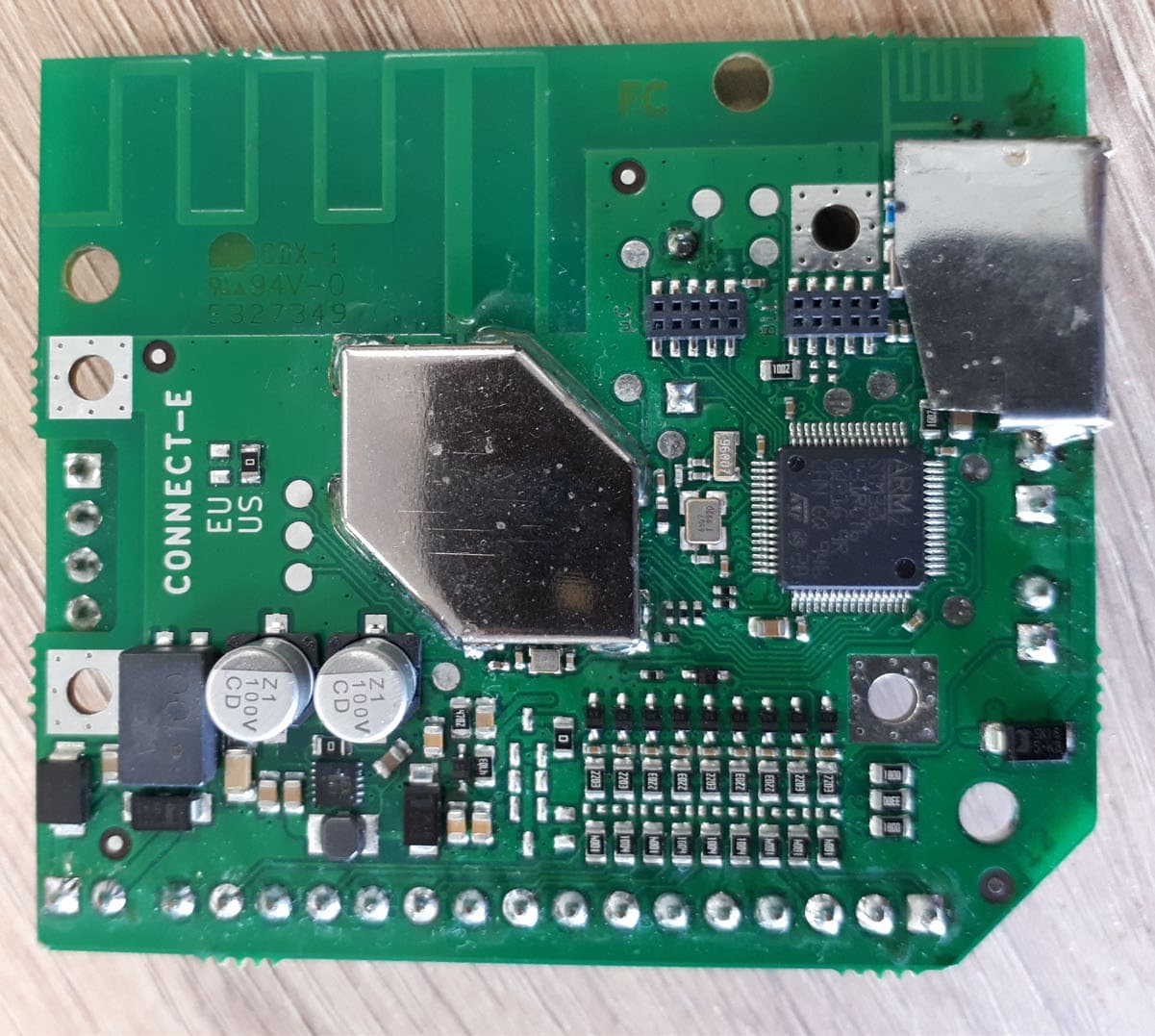
Click to zoom
Application Details
- Equipment Class
- DTS - Digital Transmission System
- Date of Grant
- Jun 27, 2021
- Application Purpose
- Original Equipment
- Date of Application
- Jun 24, 2021
- Equipment Note
- Connect Radio Module (BLE-LoRa)
- Frequency Range
- 906.00000000 - 924.00000000
- Company
- SORHEA Inc
- Country
- United States
Documents & Files
Document Text
Text extracted from the exhibit documents filed with the FCC. Open a document above to read the original.
Users Manual
SORADIO SORADIO Installation instructions - Pages 2- 15 529 VISTA BLVD 89434 SPARKS, NV - USA Toll Free: 1-800-498-9662 / Phone: (775) 856-7333 / Fax: (775) 856-7658 Website: www.protechusa.com E-mail: [email protected] EN PROTECH SORADIO 1 PROTECH SORADIO CONTENTS 1 WIRING ............................................................................................................. 2 2 SMARTPHONE APPLICATION ........................................................................ 3 2.1 Settings .............................................................................................................................. 4 2.2 Input status ........................................................................................................................ 4 2.3 Input settings ..................................................................................................................... 5 2.4 User settings ...................................................................................................................... 5 2.5 Event log ............................................................................................................................ 7 2.6 Network settings ................................................................................................................ 8 3 RADIO CONFIGURATION ................................................................................ 9 3.1 Configuration using the CONNECT RADIO COORDINATOR ........................................... 9 3.2 Activate the radio on the SORADIO ................................................................................. 11 4 MAINTENANCE .............................................................................................. 12 5 TECHNICAL SPECIFICATIONS ..................................................................... 12 6 PRODUCT REFERENCES .............................................................................. 13 2 PROTECH SORADIO 1 WIRING Note: All common inputs are connected together. Example of input wiring: The inputs are seen out of alarm when they are closed. They are seen in alarm when they are open (Positive security). * LEDs status L1, L2 et L3: L1: green Operating mode OFF: Radio Mode ON: RS485 Mode (unused in SORADIO) LEDs active only if BLE is activated after a short press on the tamper L2: orange Radio configuration status Blinking: Radio mode not configured ON: Radio mode configured L3: red BLE status OFF: BLE deactivated Blinking: BLE active waiting for connection ON: BLE active connected to the application Maximum length of 12V DC power supply cables: (cable type SYT1 shielded) ∅ Wire Wire section Maximum length of cables 0.6 mm 0.02 in 0.3 mm² 23 AWG 500 m 0.31 mi 0.9 mm 0.04 in 0.6 mm² 20 AWG 1124 m 0.7 mi 1.4 mm 0.06 in 1.5 mm² 16 AWG 2506 m 1.56 mi Note: When using the same cable to supply power to several components, the indicated distances should be divided by the number of connected components. When using several wires with the same section in parallel by polarity, the indicated distances should be multiplied by the number of connected wires. N° Terminals Description 1 Input 1 2 Common 3 Input 2 4 Common 5 Input 3 6 Common 7 Input 4 8 Common 9 Input 5 10 Common 11 Input 6 12 Common 13 Input 7 14 Common 15 Input 8 16 Common 17 X 18 X 19 X 20 X 21 0V Power supply 22 +12V DC Power supply E1 C * L1 L2 L3 3 PROTECH SORADIO 2 SMARTPHONE APPLICATION Note: The smartphone application is compatible from Android 4.1 or higher. 1. Download the smartphone application “Sorhea Connect”. 2. Launch application “Sorhea Connect”. Authorize activation of Bluetooth if requested to do so by the application. 3. Press the tamper switch very briefly (1s) to activate the BLE connection of the SORADIO. Note: the connection remains active as long as the SORADIO is connected to the smartphone application. It is deactivated when the cover is closed (tamper closed) or after 1 minute of inactivity (application closed). 4. Launch the search. Sorhea Connect Tamper SORADIO 4 PROTECH SORADIO 5. Click on the product found. 2.1 Settings 2.2 Input status Note: It is possible to customize the name of an input. Click on the name to change and Save. Enter the module name: Click on the name to change and Save Setting the time on the module Real-time input status Legend: No alarm Alarm Inactive SORADIO found Radio ID of the SORADIO found identical to the sticker on the card. 5 PROTECH SORADIO 2.3 Input settings Each input can be: • Enable / disable input. • Eject input. To apply the changes, click Save. Enable input Input disabled Input enabled Eject input Input not ejected Input ejected Note: It is only possible to eject an input if it is enable. Input disable = Relay associated forced in alarm Input ejected = Relay associated forced out alarm. 2.4 User settings Managing user settings allows saving settings or applying settings to inputs: name and status of inputs (activated, ejected). 2.4.1 Saving user configuration Select Input disable input Eject input Select “Save configuration” Enter the name of the backup file Click “SAVE” Not used 6 PROTECH SORADIO 2.4.2 Applying an existing user setting By default, the application offers the following setting options: → SO-BEAM S RX (FR) → SO-BEAM M/L/XL Mixed (FR) → SO-BEAM M/L/XL TX (FR) → SO-BEAM M/L/XL RX (FR) → SO-BEAM M/L/XL TX (EN) → SO-BEAM S RX (EN) → SO-BEAM M/L/XL RX (EN) → SO-BEAM M/L/XL Mixed (EN) → MIRIS 3000/3100 CONNECT Sigle Direction (FR) → MIRIS 3000/3100 CONNECT Double Direction (FR) → COLIRIS II CONNECT Sigle Direction (FR) → COLIRIS II CONNECT Double Direction (FR) → MIRIS 3000/3100 CONNECT Sigle Direction (EN) → MIRIS 3000/3100 CONNECT Double Direction (EN) → COLIRIS II CONNECT Double Direction (EN) → COLIRIS II CONNECT Sigle Direction (EN) → 8 INPUTS REMOTE MODULE default settings Select the settings to load Click on “Apply configuration” 7 PROTECH SORADIO 2.5 Event log 1. Click on Menu 2. Click on Event log 3. View eve…
Text truncated - open the document above for the full version.
Cover Letter(s)
··1 SDAHEA __/ •• •••• ••••• ••• ••••••••••• ••••••••••••••••••••••••••• ••••••••••• •••••••••••••••• ••••••••••••••••••••••••••• ........ ., .......................... . • •••••••••••••••••••• ••• •••••••• •••••••••• Authority to Act as Agent Date: November 27 th , 2020 A merican Certification Body, Inc. 6731 Whittier Avenue Suite C1 10 Mclean, VA 22101 To Whom lt May Concern: SMEE (Mr. Laurent Chapus, 385 Rue René Rambaud, F-38500 Voiron, France) is authorized to act on our behalf, until otherwise notified, for applications to American Certification Body, Inc. (ACB). We c ertify that we are not subject to de niai of federal benefits, that includes FCC benefits, p ursuant to Section 5301 of the Anti-Drug Abuse Act of 1988, 21 U.S.C. 862. Further, no party, as defined in 47 CFR 1.2002 (b), to the application is subject to denial of federal b enefits, that includes FCC benefits. We also declare that the information provided to the FCC is true and correct to the best of our knowledge (47 CFR 2.911(d)) and we have been informed of the grantee res ponsibilities (47 CFR 2.909) with regard to certified equipment. Thank you, __ Mr. Aymeric CARADEC (Print name) Title: __ Technical Department Manager _____ _ On behalf of: SORHEA 1 rue du Dauphiné F-69120 VAULX-EN-VELIN (France) [email protected] Phone: +33(0)4 78 03 06 10 1 rue du Dauphiné - F-69120 VAULX-E -VE IN Tél. : +33(0)4 78 03 06 10 Fitx : +33(0)4 78 68 24 61 Email: [email protected] $ , OIP't•I ,<QO 000 C • li.CS L )◄I Il 7 0 , SIRET l4 l 817 609 000}) • Af>E 2 )OZ • n A I tncon " • ••• fR 73 l◄I 817 609 --
Cover Letter(s)
- · 1 SDAHEA _/ ••••••• •••••••• •••••• •••• ••••••••••••••o•••••• •••• ••••••••••••• ••••••••• •••••••••••••• 011 ••••••••• •••••••• ••••• ••• •• •••••011110111111 .... , ...•.•......•..••.•. •......•..••.••. Reguest for Confidentiality Date: November 27 tl1 , 2020 Subject: Confidentiality Request for FCC ID: QV A-SORADIO IC: l 1664A-SORADIO Pursuant to FCC 4 7 CFR 0.457( d) and 0.459 and IC RSP- 100, Section 2.4, the applicant requests that a part of the subject F CC application be held confidential. Type of Confidentiality Requested D Short Term [8] Permanent D Short Term D Short Term D ShortTerm D ShortTerm D Short Term D Short Term D ShortTerm D ShortTerm D Permanent* 1 [8] Permanent D Permanent D Permanent [8] Permanent D Permanent* 3 Exhibit Block Diagrams External Photos Internai Photos Operation Description/Theory of Operation Parts List & Placement/BOM Tune-Up Procedure Schematics Test Setup Photos User's Manual SORHEA has spent substantial effort in developing this product and it is one of the first of its kind in industry. Having the subject information easily available to "competition" would negate the advantage they have achieved by developing this product. Not protecting the details of the design will result in financial hardship. Permanent Confidentiality: The applicant requests the exhibits listed above as permanently confidential be permanently withheld from public review due to materials that contain trade secrets and proprietary information not customarily released to the public. Short-Term Confidentiality: The applicant requests the exhibits selected above as short term confidential be withheld from public view for a period of (specify number of days not to exceed 180) 2 _ days from the date of the Grant ofEquipment Authorization and prior to marketing. This is to avoid premature release of sensitive information prior to marketing or release of the product to the public. Applicant is also aware that they are responsible to notify ACB in the event information regarding the product or the product is made available to the public before the requested period has expired. ACB will then release the documents listed above for public disclosure pursuant to FCC Public Notice DA 04-1705. NOTE for Industry Canada Applications: IC currently only distinguishes Permanent Confidentiality exhibits as shown above. Short Term confidentiality is not considered applicable to IC applications. Sincerely, � C---J'-j �� �-�---,,---- (S ignature/Titie 3 ) By : Technical Department Manager _____ Aymeric CARADEC _____ _ (Print name) SORHEA 1 rue du Dauphiné F- 69120 VAULX-EN-VELIN - France 1 The asterisked items (*) require further information to be provided to ACB before permanent confidentiality will be extended to these exhibits. Please refer to FCC KDB 726920 and the specific Document link for DO 1 found at: https://apps.fcc.gov/oetcf/kdb/forms/FTSSearchResultPage.cfm?switch = P&id = 41 73 l and review section II, 3) regarding specific information that must accompany these requests. 2 -Please refer to http://acbcert.com/documents/misc-docs/Memo-Short-Term-Vs-Standard-Confidentiality.pdf for complete details. 1 rue du Dauphinè - F-69120 VAULX-E -VELIN Tél. : 33(0)4 78 03 06 10 Fax : +33(0)4 78 68 24 61Email : [email protected] S.A � p,1 1 d ,oo 000 C. li.CS L 1 on 341 8 7 609. SIRET 3• 817 609 00033 • .,,_PE l!>lOZ • .,• A l<>,r• o , r FR 73 J◄I 817 609
Cover Letter(s)
Request for Modular/Limited Modular Approval Date: June 2, 2021 Subject: Manufacturer’s Declaration for ☒ - Modular Approval ☐ - Split Modular Approval ☐ - Limited Modular Approval ☐ - Limited Split Modular Approval Confidentiality Request for: ___________ 8 Basic Requirements – FCC Part 15.212(a)(1) For Items Marked “NO(*)”, the Limited Module Description Must be Filled Out on the Following Pages Modular Approval Requirement Requirement Met 1. The modular transmitter must have its own RF shielding. This is intended to ensure that the module does not have to rely upon the shielding provided by the device into which it is installed in order for all modular transmitter emissions to comply with FCC limits. It is also intended to prevent coupling between the RF circuitry of the module and any wires or circuits in the device into which the module is installed. Such coupling may result in non-compliant operation. The physical crystal and tuning capacitors may be located external to the shielded radio elements. 15.212(a)(1)(i) ☒ - YES ☐ - NO(*) Details: The module contains a metal shield which covers all RF components and circuitry. The shield is located on the top of the board next to antenna. 2. The modular transmitter must have buffered modulation/data inputs (if such inputs are provided) to ensure that the module will comply with FCC requirements under conditions of excessive data rates or over-modulation. 15.212(a)(1)(ii) ☒ - YES ☐ - NO(*) Details: No modulation / data inputs 3. The modular transmitter must have its own power supply regulation on the module. This is intended to ensure that the module will comply with FCC requirements regardless of the design of the power supplying circuitry in the device into which the module is installed. 15.212(a)(1)(iii) ☒ - YES ☐ - NO(*) Details: Voltage regulators on module or inside MCU and RF integrated circuit. 4. The modular transmitter must comply with the antenna and transmission system requirements of §§ 15.203, 15.204(b), 15.204(c), 15.212(a), and 2.929(b). The antenna must either be permanently attached or employ a ‘‘unique’’ antenna coupler (at all connections between the module and the antenna, including the cable). The ‘‘professional installation’’ provision of § 15.203 is not applicable to modules but can apply to limited modular approvals under paragraph 15.212(b). 15.212(a)(1)(iv) ☒ - YES ☐ - NO(*) Details: The module has its own antenna soldered on the PCB 5. The modular transmitter must be tested in a stand-alone configuration, i.e., the module must not be inside another device during testing. This is intended to demonstrate that the module is capable of complying with Part 15 emission limits regardless of the device into which it is eventually installed. Unless the transmitter module will be battery powered, it must comply with the AC line conducted requirements found in Section 15.207. AC or DC power lines and data input/output lines connected to the module must not contain ferrites, unless they will be marketed with the module (see Section 15.27(a)). The length of these lines shall be length typical of actual use or, if that length is unknown, at least 10 centimeters to insure that there is no coupling between the case of the module and supporting equipment. Any accessories, peripherals, or support equipment connected to the module during testing shall be unmodified or commercially available (see Section 15.31(i)). 15.212(a)(1)(v) ☒ - YES ☐ - NO(*) Details: The module was tested stand-alone as shown in test setup photographs filed with this application Modular Approval Requirement Requirement Met 6. The modular transmitter must be labeled with its own FCC ID number, or use an electron display (see KDB Publication 784748). If using a permanently affixed label with its own FCC ID number, if the FCC ID is not visible when the module is installed inside another device, then the outside of the device into which the module is installed must also display a label referring to the enclosed module. This exterior label can use wording such as the following: “Contains Transmitter Module FCC ID: XYZMODEL1” or “Contains FCC ID: XYZMODEL1.” Any similar wording that expresses the same meaning may be used. The Grantee may either provide such a label, an example of which must be included in the application for equipment authorization, or, must provide adequate instructions along with the module which explain this requirement. In the latter case, a copy of these instructions must be included in the application for equipment authorization. If the modular transmitter uses an electronic display of the FCC identification number, the information must be readily accessible and visible on the modular transmitter or on the device in which it is installed. If the module is installed inside another device, then the outside of the device into which the module is installed must display a label referring to the enclosed module. This exterior label can use wording such as the following: “Contains FCC certified transmitter module(s).” Any similar wording that expresses the same meaning may be used. The user manual must include instructions on how to access the electronic display. A copy of these instructions must be included in the application for equipment authorization. 15.212(a)(1)(vi) ☒ - YES ☐ - NO(*) Details: There is a label on the module as shown in the labeling exhibit filed with this application. Host specific labeling instructions are shown in the installation manual filed with this application. 7. The modular transmitter must comply with all specific rule or operating requirements applicable to the transmitter, including all the conditions provided in the integration instructions by the grantee. A copy of these instructions must be included in the application for equipment authorization. For example, there are very strict operational and timing requirements that must be met before a transmitter is authorized for operation under Section 15.231. For insta…
Text truncated - open the document above for the full version.
External Photos
FCC ID: QVA-SORADIO IC: 11664A-SORADIO Page 1/1 EXTERNAL PHOTOS OF TESTED EUT
ID Label/Location Info
FCC ID: QVA-SORADIO IC: 11664A-SORADIO Page 1/1 PRODUCT LABELING
Internal Photos
FCC ID: QVA-SORADIO IC: 11664A-SORADIO INTERNAL PHOTOS OF TESTED EUT Shields removed
RF Exposure Info
COORDONNEES SMEE TEL : 04 76 65 76 50 385, Rue Renè Rambaud, ZA le Parvis 2 FAX : 04 76 66 18 30 38500 VOIRON - France SAS au capital de 50 000 € / RC Grenoble B534 796 453 / SIRET 534 796 453 00015 / code APE 7490B / n° TVA : FR 59 534 796 453 RF Exposure Considerations for FCC ID: FCC ID: QVA-SORADIO The calculation of the MPE is as following: Prediction of MPE limit at a prediction distance: S= ²..4 . R GP ∏ = ² .. 4 .. . R P RI E ∏ S: Power density (mW/cm²) P: Peak output power at antenna terminal (mW) G: Numerical Antenna gain R: Distance of radiation to antenna (cm) MPE calculation Conclusion: Therefore the device complies with FCC’s RF radiation exposure limits for general population for a mobile device. Certified By Laurent CHAPUS (Agent for this device) SMEE 385, Rue René Rambaud ZA Le Parvis 2 38500 Voiron - France [email protected] FCC Registration Number: 0020356952 (FRN) Applicant for this device: SORHEA 1 rue du Dauphiné F-69120 VAULX-EN-VELIN Aymeric CARADEC Technical Department Manager [email protected] +33(0)4 78 03 06 10 Frequency (MHz) Maximum E.I.R.P. (mW) R (cm) Power Density S (mW/cm²) MPE limit (mW/cm²) % of limit Limit (%) Verdict 2402-2480 1.0 20 0.0002 1.0 0.02 - Below MPE limit for uncontrolle d exposure 906-924 28.2 20 0.0056 0.6 0.94 - Simultaneous transmissions SUM = 0.96 100%
Test Report
Rapport d’essais / Test Report N° : 13647-FCC-IC-2 Page 1 / 29 COORDONNEES SMEE TEL : 04 76 65 76 50 385, Rue René Rambaud, ZA Le Parvis 2 FAX : 04 76 66 18 30 38500 VOIRON - France SAS au capital de 50 000 € / RC Grenoble B534 796 453 / SIRET 534 796 453 00015 / code APE 7490B / n° TVA : FR 59 534 796 453 FCC Test Firm Designation Number: FR0014 ISED Wireless Device Testing Laboratory CAB Number: FR0004 Matériel testé : Equipment under test: SORHEA / SORADIO (Trademark / Marketing name or product reference) (BLE radio communication link) Demandeur de certification : Applicant for certification: SORHEA 1, rue du Dauphiné 69120 Vaulx en Velin - France Client : Customer: SORHEA 1, rue du Dauphiné 69120 Vaulx en Velin – France Numéro d’affaire : Work number : 13647 Référence de la proposition : Proposal number: 062020-24121 Date de l’essai : Date of test: Du 27 janvier au 19 avril 2021 January 27 th to April 19th, 2021 Objectif des essais : Test purpose: EMC qualification accordingly to following standards: - CFR 47, FCC Part 15, Subpart C (Chapter 15.247 - Operation within the bands 902–928 MHz, 2400–2483.5 MHz, and 5725–5850 MHz) - Industry Canada RSS-247, Issue 2 (Digital Transmission Systems Operating in the Bands 902–928 MHz) Measurement standards: ANSI C63.10 (2013) Lieu du test: Test location: SMEE, 385 Rue René Rambaud 38500 VOIRON - France Test réalisé par : Test realized by: Laurent CHAPUS Conclusion : Conclusion: L’équipement satisfait aux prescriptions et essais des normes citées en référence. The appliance complies with requirements and tests of above mentioned standards. Ed. Date Modifications / Pages Written by : Visa Approved by: Visa 1 2 April 23 rd , 2021 June 23 rd , 2021 Initial Edition TCB review ATCB027055 file Laurent CHAPUS Technical Manager Regis ANCEL General Manager La copie de ce document n'est permise que sous sa forme intégrale. Ce document est le résultat d’essais effectués sur un échantillon. Il ne préjuge pas de la conformité de l’ensemble des produits fabriqués à l’objet essayé. This document shall not be reproduced, except in full. This document contains results related only to the item tested. It does not imply the conformity of the whole production to the item tested. Accréditation N° 1-6356 Portée disponible sur : Scope available on : www.cofrac.fr Page 2 / 29 Rapport d’essai / Test Report N° : 13122-FCC-IC-2 Contents 1. NORMATIVES REFERENCES ......................................................................................................... 3 2. TEST SYNTHESIS ............................................................................................................................ 4 3. EQUIPMENT UNDER TEST (EUT) ................................................................................................... 5 4. TEST CONDITIONS.......................................................................................................................... 5 5. MODIFICATIONS OF THE EUT ........................................................................................................ 5 6. SPECIAL ACCESSORY .................................................................................................................... 6 7. MEASUREMENT UNCERTAINTY .................................................................................................... 6 8. FIELD STRENGTH CALCULATION .................................................................................................. 6 9. TEST SETUP DIAGRAM ................................................................................................................... 7 10. CONDUCTED EMISSION MEASUREMENT (150KHZ-30MHZ) .................................................... 9 11. DTS BANDWIDTH ....................................................................................................................... 11 12. MAXIMUM PEAK OUTPUT POWER ........................................................................................... 13 13. MAXIMUM POWER SPECTRAL DENSITY LEVEL IN THE FUNDAMENTAL EMISSION ........... 15 14. UNWANTED EMISSIONS IN NON-RESTRICTED FREQUENCY BANDS (RADIATED EMISSIONS) .......................................................................................................................................... 18 15. UNWANTED EMISSIONS IN RESTRICTED FREQUENCY BANDS ........................................... 20 16. OCCUPIED BANDWIDTH (99%) ................................................................................................. 27 17. TEST EQUIPMENT LIST ............................................................................................................. 29 Page 3 / 29 Rapport d’essai / Test Report N° : 13122-FCC-IC-2 1. Normatives References FCC qualification according to: Standards Applied Title ANSI C63.10 (2013) X American National Standard for Testing Unlicensed Wireless Devices CFR47, Part 15 (April 2021) X Telecommunication – Federal Communication Commission – Radio frequency devices, Sections 15.207 / 15.209 / 15.247 ISED qualification according to: Standards Applied Title RSS-Gen (Issue 5/2018, amendments 2019 and 2021 ) X General Requirements and Information for the Certification of Radio Apparatus RSS-247 (Issue2/2017) X Digital Transmission Systems (DTSs), Frequency Hopping Systems (FHSs) and Licence-Exempt Local Area Network (LE-LAN) Devices Note: Following guidance are used - DTS Measurement Guidance 558074 D01 v05r02 - Determining ERP and EIRP Guidance 412172 D01 v01r01 Deviation from standard: None Page 4 / 29 Rapport d’essai / Test Report N° : 13122-FCC-IC-2 2. Test synthesis TEST Paragraph number FCC Part 15 / ISED ICES & RSS Spec. FCC Part 15 / ISED ICES & RSS RESULTS (comments) Conducted emissions test 15.207 (a) RSS-Gen § 8.8 Table 15.107 (a) / 15.207 (a) Table 4 / RSS-Gen PASS 6dB Bandwidth 15.247 (a) (2) RSS-247 § 5.2 (a) At least 500kHz PASS Maximum Peak Output Power 15.247 (b) (3) & (4) RSS-247 § 5.4 (d) 1W max / 30dBm (Conducted) 4W max / 3…
Text truncated - open the document above for the full version.
Test Report
Rapport d’essais / Test Report N° : 13647-FCC-IC-1 Page 1 / 31 COORDONNEES SMEE TEL : 04 76 65 76 50 385, Rue René Rambaud, ZA Le Parvis 2 FAX : 04 76 66 18 30 38500 VOIRON - France SAS au capital de 50 000 € / RC Grenoble B534 796 453 / SIRET 534 796 453 00015 / code APE 7490B / n° TVA : FR 59 534 796 453 FCC Test Firm Designation Number: FR0014 ISED Wireless Device Testing Laboratory CAB Number: FR0004 Matériel testé : Equipment under test: SORHEA / SORADIO (Trademark / Marketing name or product reference) (902-928MHz radio communication link) Demandeur de certification : Applicant for certification: SORHEA 1, rue du Dauphiné 69120 Vaulx en Velin - France Client : Customer: SORHEA M. Aymeric Caradec 1, rue du Dauphiné 69120 Vaulx en Velin - France Numéro d’affaire : Work number : 13647 Référence de la proposition : Proposal number: 062020-24121 Date de l’essai : Date of test: Du 26 janvier au 19 avril 2021 January 26 th to April 19th, 2021 Objectif des essais : Test purpose: EMC qualification accordingly to following standards: - CFR 47, FCC Part 15, Subpart C (Chapter 15.247 - Operation within the bands 902–928 MHz, 2400–2483.5 MHz, and 5725–5850 MHz) - Industry Canada RSS-247, Issue 2 (Digital Transmission Systems Operating in the Bands 902–928 MHz) Measurement standards: ANSI C63.10 (2013) Lieu du test: Test location: SMEE, 385 Rue René Rambaud 38500 VOIRON - France Test réalisé par : Test realized by: Laurent CHAPUS Conclusion : Conclusion: L’équipement satisfait aux prescriptions et essais des normes citées en référence. The appliance complies with requirements and tests of above mentioned standards. Ed. Date Modifications / Pages Written by : Visa Approved by: Visa 1 2 April 23 rd , 2021 June 23 rd , 2021 Initial Edition TCB review ATCB027055 file Laurent CHAPUS Technical Manager Regis ANCEL General Manager La copie de ce document n'est permise que sous sa forme intégrale. Ce document est le résultat d’essais effectués sur un échantillon. Il ne préjuge pas de la conformité de l’ensemble des produits fabriqués à l’objet essayé. This document shall not be reproduced, except in full. This document contains results related only to the item tested. It does not imply the conformity of the whole production to the item tested. Accréditation N° 1-6356 Portée disponible sur : Scope available on : www.cofrac.fr Page 2 / 31 Rapport d’essai / Test Report N° : 13647-FCC-IC-1 Contents 1. NORMATIVES REFERENCES ......................................................................................................... 3 2. TEST SYNTHESIS ............................................................................................................................ 4 3. EQUIPMENT UNDER TEST (EUT) ................................................................................................... 5 4. TEST CONDITIONS.......................................................................................................................... 5 5. MODIFICATIONS OF THE EUT ........................................................................................................ 5 6. SPECIAL ACCESSORY .................................................................................................................... 5 7. MEASUREMENT UNCERTAINTY .................................................................................................... 6 8. FIELD STRENGTH CALCULATION .................................................................................................. 6 9. TEST SETUP DIAGRAM ................................................................................................................... 7 10. CONDUCTED EMISSION MEASUREMENT (150KHZ-30MHZ) .................................................... 9 11. DTS BANDWIDTH ....................................................................................................................... 12 12. MAXIMUM PEAK OUTPUT POWER ........................................................................................... 14 13. MAXIMUM POWER SPECTRAL DENSITY LEVEL IN THE FUNDAMENTAL EMISSION ........... 16 14. UNWANTED EMISSIONS IN NON-RESTRICTED FREQUENCY BANDS (RADIATED EMISSIONS) .......................................................................................................................................... 19 15. UNWANTED EMISSIONS IN RESTRICTED FREQUENCY BANDS ........................................... 22 16. OCCUPIED BANDWIDTH (99%) ................................................................................................. 29 17. TEST EQUIPMENT LIST ............................................................................................................. 31 Page 3 / 31 Rapport d’essai / Test Report N° : 13647-FCC-IC-1 1. Normatives References FCC qualification according to: Standards Applied Title ANSI C63.10 (2013) X American National Standard for Testing Unlicensed Wireless Devices CFR47, Part 15 (April 2021) X Telecommunication – Federal Communication Commission – Radio frequency devices, Sections 15.109 / 15.209 / 15.247 ISED qualification according to: Standards Applied Title RSS-Gen (Issue 5/2018, amendments 2019 and 2021 ) X General Requirements and Information for the Certification of Radio Apparatus RSS-247 (Issue2/2017) X Digital Transmission Systems (DTSs), Frequency Hopping Systems (FHSs) and Licence-Exempt Local Area Network (LE-LAN) Devices Note: Following guidance are used - DTS…
Text truncated - open the document above for the full version.
Contact Information
Applicant
Eric THORD(Treasurer)
Test Firm
SMEELaurent Chapus
[email protected]+33 4 76 65 76 50
Technical Specifications
| # | Rule Parts | Frequency Range | Power Output |
|---|---|---|---|
| 2 | 15C | 906 MHz - 924 MHz | 28.00 mW |