QVBGS002GS025: Radio Anemometer, GS085: Radio Ant-Two-Block
Load Systems International, Inc.
Click to zoom
Application Details
- Equipment Class
- DTS - Digital Transmission System
- Date of Grant
- Jan 22, 2013
- Application Purpose
- Original Equipment
- Date of Application
- Jan 22, 2013
- Equipment Note
- GS025: Radio Anemometer, GS085: Radio Ant-Two-Block
- Frequency Range
- 903.00000000 - 927.00000000
- Country
- Canada
Documents & Files
Document Text
Text extracted from the exhibit documents filed with the FCC. Open a document above to read the original.
Users Manual
GM025_ENG_rev.docx www.loadsystems.com 1 WIRELESS TECHNOLOGY & CRANE INSTRUMENTATION DIVISIONS GS025 Radio Anemometer I I n n s s t t a a l l l l e e r r a a n n d d u u s s e e r r g g u u i i d d e e WARNING! Carefully read and understand this manual and the GS320/GS550/GS820 Installer and User’s manual before proceeding. Manual before proceeding. GM025_ENG_rev.docx www.loadsystems.com 2 IMPORTANT! Refer to the “GS320/GS550/GS820 Display & GS Series Sensors - Installer and User’s Manual” for complete information about installation, operation, maintenance, certification and warranty. GM025_ENG_rev.docx www.loadsystems.com 3 Read and understand the following: For your safety and that of the people that come into contact with LSI products, understand the significance of the instructions included in this guide, respect all laws and regulations and comply with applicable standards. Pay particular attention to text boxes and the following words: Warning: this denotes an instruction that if not complied with may lead to serious injury or death. Important: this denotes an instruction that if not complied with may lead to product performance issues. 1. Overview ........................................................................................................................................ 4 2. Location ......................................................................................................................................... 4 3. Installation ..................................................................................................................................... 4 4. Operation ...................................................................................................................................... 5 5. Security .......................................................................................................................................... 5 6. Battery replacement ...................................................................................................................... 5 7. Replacement parts ........................................................................................................................ 5 Table of contents WARNING! Installation must be made in compliance with LSI instructions and using LSI supplied components only. Failure to install all parts, or replacing parts or components with parts or components not supplied by LSI, may lead to system failure, serious injury or death. IMPORTANT! WARNING! BEFORE PROCEEDING GM025_ENG_rev.docx www.loadsystems.com 4 1. Overview The GS025 is a magnetically encoded radio anemometer. The wind speed values are computed from pulses of magnets inserted in the rotor. This means that this anemometer has no adjustment and thus never needs to be calibrated. Its battery powered electronics gives it an extended autonomy and the radio connection allows it to be installed in remote locations with difficult access. Both the battery and rotor can be field serviced without the need for tools. 2. Location The anemometer location should be on the same side of the boom as the cabin mounted display, perpendicular to the boom, and at the highest point possible. The wind speed sensor must pivot freely on the mounting mast at all boom angles. The wind cups must be fully exposed to the wind and spin freely at all boom angles. There should be a clear and unobstructed line of sight between the anemometer sensor and the cabin mounted display unit. 3. Installation Weld or screw the mast to the boom at the selected position. Note: An iron angle can be used to extend the reach of the mast to clear the boom tip. The U-bolt can be used when retrofitting the GS025 on an already installed GS020 rod (previous generation anemometer). Make sure the U-bolt is fully tightened and add the washer and cotter pin at the rod tip. Once the mast is secured in place the radio anemometer can be inserted on the pivot and secured in place by the washer and hairpin. IMPORTANT! Do not weld in proximity to LSI sensor/transmitters. Mast GS020 Rod U-Bolt Washer & cotter pin Cab Anemometer Line of sight GM025_ENG_rev.docx www.loadsystems.com 5 4. Operation The radio anemometer is fully functional. It does not need to be calibrated or adjusted. Refer to the GS320/GS550/GS820 manual for how to add this sensor to the sensor list to be displayed. 5. Security The radio anemometer is equipped with a failsafe power system allowing it to communicate instantaneously an alarm via radio signals if the battery of the power circuit is rendered inoperative. In the advent of a radio failure, the radio communication protocol will generate an alarm within 5 minutes of the loss of signal. 6. Battery replacement After a period of about 4 years, the battery may need to be replaced. To ensure the same performance as the supplied battery, replace with: 3.6V lithium D cell If this type of battery is not available, this type can be used but with a reduced life: 1.5V Alkaline D cell To replace a battery, turn the battery cover ¼ turn counter clock wise and remove, the battery can then be changed and reclose the battery cover by turning ¼ turn clock wise. 7. Replacement parts PD058-A: rotor assembly GM025_ENG_rev.docx www.loadsystems.com 6 8. FCC and IC – Instructions to the User This equipment has been tested and found to comply with the limits for a class B digital device, pursuant to part 15 of the FCC Rules. These limits are designed to provide reasonable protection against harmful interference in a residential installation. This equipment generates, uses, and can radiate radiofrequency energy and if not installed and used in accordance with the instructions, may cause harmful interference to radio communications. However, there is no guarantee that interference will not occur in a particular installation. If this equipment does cause harmful interference to radio or television reception, which can be determined by turning the equipment off and on, t…
Text truncated - open the document above for the full version.
ID Label/Location Info
PDF NAME: Template_V GS085 Label THE INFORMATION CONTAINED IN THIS DRAWING IS THE SOLE PROPERTY OF LOAD SYSTEMS INTERNATIONAL. ANY REPRODUCTION IN PART OR AS A WHOLE WITHOUT THE WRITTEN PERMISSION OF LOAD SYSTEMS INTERNATIONAL IS PROHIBITED. PROPRIETARY AND CONFIDENTIAL UNLESS OTHERWISE SPECIFIED DIMENSION ARE IN INCHES TOLERANCE ARE : DECIMALS FRACTIONS X 0.1 < 1/4 1/64 X.X 0.05 > 1/2 1/32 X.XX 0.01 >=1/2 1/16 X.XXX 0.002 ANGLE 0.5 X.XXXX 0.0005 ROUGHTNESS 125 MAT. DATE CHECKED Treatment: WEIGHT DRAWN APPROVALS A. Petka2012-9-4 SCALE : Drawing to ScaleRELEASE DATE:STATUS: SIZEPRODUCT DWG. NO. A REV. SHEET 1 OF 1 UB327GS0851 Removed # symbol from FCC & IC2013-01-11AL Cut Line: 3.2284 in Cut Line: 3.2284 in This device complies with Part 15 of the FCC Rules. Operation is subject to the following two conditions: 1. This device may not cause harmful interference, and 2. This device must accept any interference received, including interference that may cause undesired operation. FCC ID: QVBGS002 IC: 7076A-ICGS002 Model #: GS085 Radio Anti-Two-Block Switch www.lsirobway.com +1 (281) 664-1330 C:\2012 Produ 19\GS025&85_ GS025 labe ction Projects\ _Labels locatio ls location: Load Systems ons.docx International\N L NEX-218419 10 SI Resea 0227062\Subm rch / Rec missions\Updat cherche L es 11- P LSI Inc Page 1 of 5 C:\2012 Produ 19\GS025&85_ ction Projects\ _Labels locatio Load Systems ons.docx International\N L NEX-218419 10 SI Resea 0227062\Subm rch / Rec missions\Updat cherche L es 11- P LSI Inc Page 2 of 5 C:\2012 Produ 19\GS025&85_ ction Projects\ _Labels locatio Load Systems ons.docx International\N L NEX-218419 10 SI Resea 0227062\Subm rch / Rec missions\Updat cherche L es 11- P LSI Inc Page 3 of 5 C:\2012 Produ 19\GS025&85_ GS085 labe ction Projects\ _Labels locatio ls location: Load Systems ons.docx International\N L NEX-218419 10 SI Resea 0227062\Subm rch / Rec missions\Updat cherche L es 11- P LSI Inc Page 4 of 5 C:\2012 Produ 19\GS025&85_ ction Projects\ _Labels locatio Load Systems ons.docx International\N L NEX-218419 10 SI Resea 0227062\Subm rch / Rec missions\Updat cherche L es 11- P LSI Inc Page 5 of 5
RF Exposure Info
Prediction of MPE limit at a given distance S = power density P = power input to the antenna G = antenna gain R = distance Conducted output power:13.21(dBm) 21(mW) 0.021(W) Antenna gain:0.5(dBi) Maximum antenna gain:1.122(numeric) EIRP0.0235(W) Distance:20(cm) Duty Cycle:100(%) Frequency:2400(MHz) MPE Limit:1(mW/cm^2) Power density:0.00467(mW/cm^2) 0.0467(W/m^2) Margin23.3(dB) 2 4R PG S p =
Test Report
FCC 15.247 and RSS-210 A8.docx - Date: October 2012 www.nemko.com Compliance test report ID 218419-1TRFWL Date of issue November 13, 2012 FCC 47 CFR Part 15 Subpart C, §15.247 Operation in the 902–928 MHz, 2400–2483.5 MHz, 5725–5850 MHz and RSS-210, Issue 8 Annex 8 Frequency Hopping and Digital Modulation Systems Operating in the 902–928 MHz, 2400– 2483.5 MHz, and 5725–5850 MHz Bands Applicant Load Systems International Inc. Product GS025 : Radio Anemometer and GS085 : Radio Anti Two-Block Model GS025 and GS085 FCC ID QVBGS002 IC Reg # 7076A-ICGS002 Nemko Canada Inc., a testing laboratory, is accredited by the Standards Council of Canada. The tests included in this report are within the scope of this accreditation SCC Accredited LAB LAB Accrédité CCN TM w w w . n e m k o . c o m Report reference ID: 218419-1TRFWL Page 2 of 37 Test location Nemko Canada Inc. 303 River Road Ottawa, ON, K1V 1H2 Canada FCC test site registration number: 176392 and IC registered site number: 2040A-4 (3 m semi anechoic chamber) Telephone +1 613 737 9680 Facsimile +1 613 737 9691 Toll free +1 800 563 6336 Website www.nemko.com Tested by Kevin Rose, Wireless/EMC Specialist Reviewed by November 13, 2012 Andrey Adelberg, Senior Wireless/EMC Specialist Date Limits of responsibility Note that the results contained in this report relate only to the items tested and were obtained in the period between the date of initial receipt of samples and the date of issue of the report. This test report has been completed in accordance with the requirements of ISO/IEC 17025. All results contain in this report are within Nemko Canada’s ISO/IEC 17025 accreditation. Copyright notification Nemko Canada Inc. authorizes the applicant to reproduce this report provided it is reproduced in its entirety and for use by the company’s employees only. Any use which a third party makes of this report, or any reliance on or decisions to be made based on it, are the responsibility of such third parties. Nemko Canada Inc. accepts no responsibility for damages, if any, suffered by any third party as a result of decisions made or actions based on this report. © Nemko Canada Inc. w w w . n e m k o . c o m Report reference ID: 218419-1TRFWL Page 3 of 37 Table of Contents Section 1 Report summary .................................................................................................................................................................... 4 1.1 Applicant ........................................................................................................................................................................................... 4 1.2 Manufacturer ..................................................................................................................................................................................... 4 1.3 Test specifications ............................................................................................................................................................................ 4 1.4 Test guidance ................................................................................................................................................................................... 4 1.5 Statement of compliance ................................................................................................................................................................... 4 1.6 Exclusions......................................................................................................................................................................................... 4 1.7 Test report revision history ................................................................................................................................................................ 4 Section 2 Summary of test results ........................................................................................................................................................ 5 2.1 FCC Part 15 Subpart C – general requirements, test results ............................................................................................................. 5 2.2 FCC Part 15 Subpart C – Intentional Radiators, test results .............................................................................................................. 5 2.3 IC RSS-GEN, Issue 3, test results ..................................................................................................................................................... 5 2.4 IC RSS-210, Issue 8, test results ...................................................................................................................................................... 6 Section 3 Equipment under test (EUT) details ..................................................................................................................................... 7 3.1 Sample information ........................................................................................................................................................................... 7 3.2 EUT information ................................................................................................................................................................................ 7 3.3 Technical information ........................................................................................................................................................................ 7 3.4 Product description and theory of operation ...................................................................................................................................... 7 3.5 EUT exercise details ......................................................................................................................................................................... 7 3.6 EUT setup diagram ................................................................…
Text truncated - open the document above for the full version.
Contact Information
Applicant
Eric Beaulieu(Engineer)
Technical Contact
Load Systems International Inc.Normand Labrie
[email protected]418-650-2330
4495 Blvd Hamel, suite 110 · Quebec · Canada
Non-Technical Contact
Load Systems International Inc.Bruno Pimpare
[email protected]418-650-2330
Test Firm
Nemko Canada IncStuart Beck
Technical Specifications
| # | Rule Parts | Frequency Range | Power Output |
|---|---|---|---|
| 1 | 15C | 903 MHz - 927 MHz | 21.00 mW |
Other Applications from Load Systems International, Inc.
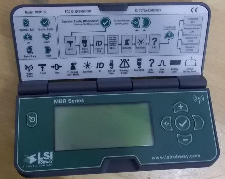
QVBMBR001
Jan 24, 2016Multi Sensor Display
Equipment Class
DTS - Digital Transmission System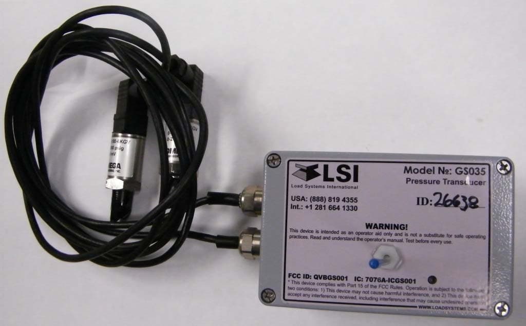
QVBGS001
May 11, 2010GS012: Angle Length Sensor; GS035: Pressure Transducer
Equipment Class
DTS - Digital Transmission System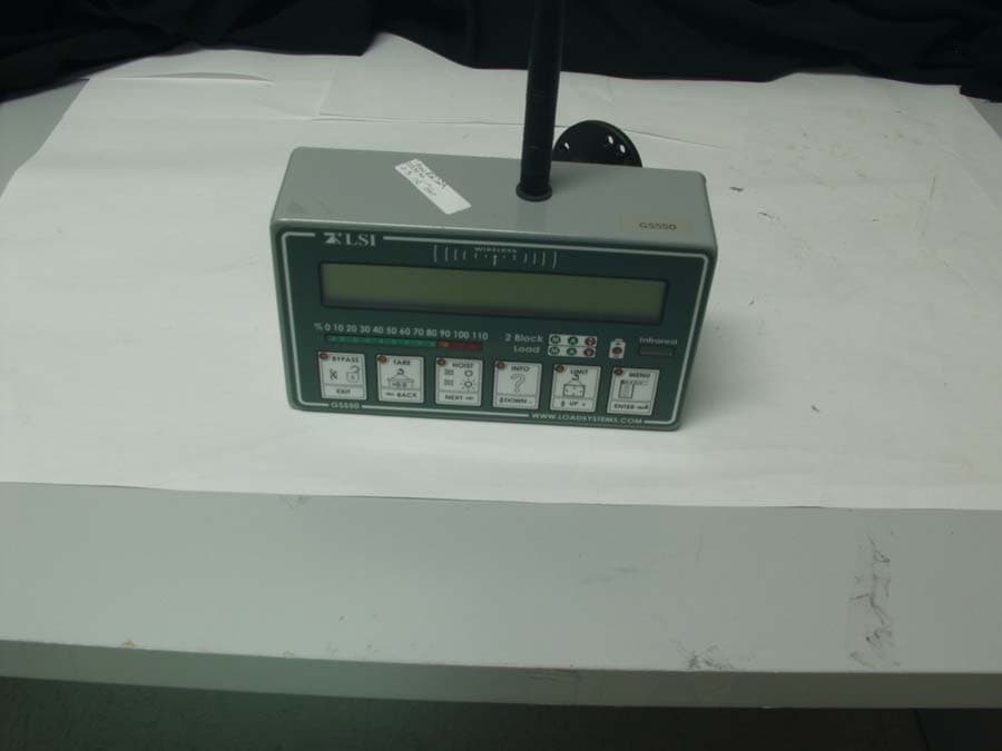
QVBGS550
May 30, 2007Spread Spectrum Transmitter
Equipment Class
DTS - Digital Transmission System
QVBGS000
May 30, 2007Spread Spectrum Transmitter
Equipment Class
DTS - Digital Transmission System
QVBGS050
May 30, 2007Spread Spectrum Transmitter
Equipment Class
DTS - Digital Transmission System