QVIS682TXRF ID Reader
Shopguard Systems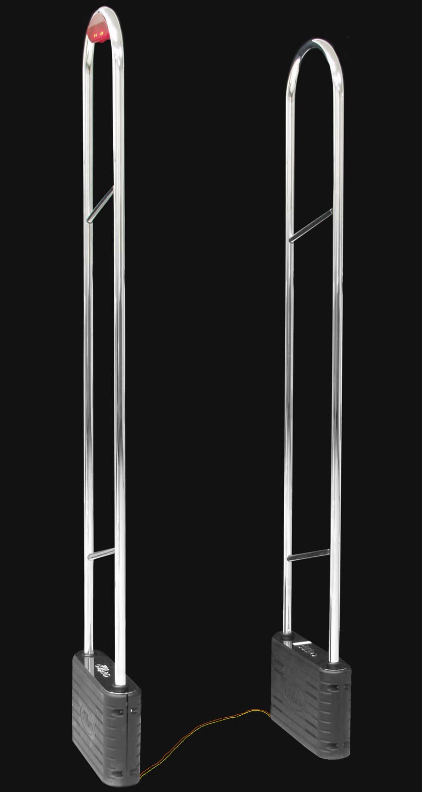
Click to zoom
Application Details
- Equipment Class
- FAP - Part 15 Anti-Pilferage Device
- Date of Grant
- Apr 17, 2003
- Application Purpose
- Original Equipment
- Date of Application
- Apr 17, 2003
- Equipment Note
- RF ID Reader
- Frequency Range
- 5.90000000 - 11.70000000
- Company
- Shopguard Systems
- Country
- Canada
Documents & Files
Document Text
Text extracted from the exhibit documents filed with the FCC. Open a document above to read the original.
Users Manual
Service Manual JuniorGuard series Rev. March/03 Table of contents: 1. Overview of the 8.2 MHz systems 2. Factors to be considered during installation 3. Parameters of Juniorguard 4. The transmitter board (TX) and its settings 5. Overview of the receiver board (RX) and the test box, possible settings 6. Examples of complete systems 7. Addendum 8. Recommended tools 9. FCC 1.Overview of 8.2 MHz systems The transmitter of the radio frequency system emits frequency modulated (generally with ±10% frequency deviation) radio signal with 8.2 MHz carrier. The security labels (tags) include LC resonator circuits tuned to a particular frequency (8.2 MHz ±5%). In the field radiated by the antenna they generate a signal clearly detectable by the receiver. The receiver analyses this signal in several cycles and based on a well-defined algorithm, according to different criteria – supposed that the signal shows the attributes of a real label – and gives an alarm. This alarm is generally an audible and visible signal, but the relay outputs are capable of driving other external devices, too. In the system developed by Shopguard we use microprocessor control, digital signal processing and correlation filters, therefore, signal detection is extremely reliable and the number of false alarms is minimal. The system handles the complete range of available tags: hard tags (drop-shaped and circular) with prints defined by the customer, guard frames for goods (safers) with wire loops (swinging coil with a single winding) or paper labels that fit for CDs, double CDs, DVDs, MCs, VIDEOs and GAMEBOY modules, as well as paper labels that can or can not be deactivated. The deactivator device for paper labels can be integrated into the system; removers for hard tags and opener for savers are also available. 2. In this section we list the circumstances that can disturb the system’s proper operation. ¾ The distance from electronic cash registers, and computer displays (and from other digitally operated equipment) should be at least 70-75 cm, ¾ Cables carrying pulse signals (e.g. cables connecting the keyboard to the alarm centre, cables connecting to regulators of air condition systems) should run at least ~70 cm from the antenna, ¾ Cables of power line equipment (230 V / 400 V) may not run in parallel (vertically) with the antenna body within ~1.5 m, ¾ Power cables should not run in the basement between the antennas, ¾ The distance between metallic objects, mirrors and the antenna should be at least 30-40 cm, ¾ Moving grids, shades, automatic doors may not be placed within ~0.5 m (1m is recommended), ¾ At switch-on (and permanently in case of faulty ignition circuit), high voltage advertising lights and any kind of gas-discharge tubes (e.g. halides lamps) produce a noise with many harmonics that reduces the system’s operability, ¾ In order to avoid mutual disturbances, the nearby goods EAS (Electronic Article Surveillance) systems must be synchronized, ¾ No labels should be placed near-by the power cable, ¾ No labels should be placed beside the antennas, within a range of 1.5 – 2 x the response distance, ¾ If possible, the antennas should not be placed beside metallic or metal bearing columns, ¾ The RX (receiver) antenna must be placed far away from the noise sources. 3.Parameters of Juniorguard It’s a very attractive styling antenna. It’s available in black, chrome, antique silver and wood variant. Available detection distances: TAGS: DISTANCES: 40x40 mm paper 130 cm Mini hard tag 160 cm Round hard tag 160 cm The necessary settings: TX RX Impedance JP 10, 11 at 3 - Tuning capacitor JP 12, 13 at 1 JP 9 at 1 Damping resistor It’s in inside of antenna It’s in inside of antenna The main characteristic parameters of the system: Height: 1.68 m / 5.51 feet Width: 0.33 m / 1.08 feet Depth: 0,09 m / 0.29 feet Weight: 8 kg Material: Chromium or colour steel tube Power: 220-240 VAC @ 50 Hz (EU) 110-120 VAC @ 60 Hz (US) 4. The transmitter board (TX) and its settings 4.1. Schematic diagram of the transmitter board: The above figure shows the schematic diagram of the transmitter circuit. Functions of the individual blocks are: Sweep oscillator: Provides the approx. 82 Hz modulation frequency for VCO. Voltage controlled oscillator (VCO): This is a voltage-controlled oscillator with 8.2 MHz output frequency. This output frequency is frequency modulated by the sweep generator. The frequency deviation is generally ±10 %. Slave inputs: If the antenna operates as a slave, we drive the power amplifier with the signal of a master transmitter. The connection can be established with cables. We use this solution with few antennas only, because it may collect and forward noises and it may cause unwanted couplings that may make impossible to operate larger systems. In larger systems (in case of certain bad environmental conditions even with 2 antennas) we use optical connections, because they are insusceptible for external electric disturbances, do not cause couplings but they are expensive, need special tools and knowledge. Optical interfaces are optional! The optical input is FOR1. Phase inverter circuits: In case of several transmitter antennas, inversion of the antenna signal phase may be needed, because the antenna signals block out each other in counter phase. Slave outputs: If we operate the board in slave mode and use cable connections, then the next board should be connected to the slave output (better if you use the Master out or CP out for synchronising because it’s amplified), and at the last member of the chain, the termination resistance should be connected by using JP1. In case of optical connection, one board should provide max.3 outputs (FOT1...3) operating in both master and slave modes. Master + CP output: In master mode, this output can drive the slave input of the next transmitter through wire connection. It operates also in slave mode; in this case it outputs the amplified signal of the previous transmitter. The Master out and…
Text truncated - open the document above for the full version.
Cover Letter(s)
Tuesday, April 15, 2003 Ruby Dulmage Submissions Specialist Nemko Canada Inc. Tel: 613-737-9680 ext 232 Fax: 613-737-9691 email: [email protected] RE: FCC for Shopguard Systems Limited Please find attached with this letter the revised block diagram as well as the new FCC warning label. Material for Label: It will be permanent Mylar type plastic label. Non-erasable. Manual: Our dealers follow a training course and then refer to the manual I sent you. For training they have other documentation that is separate from the submitted manual. Best regards, Jacques Paradis Vice-President of Marketing
Test Report
Master: PT15209 Date: December 12, 2001 Test Report:3W06524 Applicant:Shopguard Systems Equipment Under Test:JuniorGuard (EUT)8.2 MHz Transmitter FCC ID:QVIS682TX In Accordance With:FCC Part 15.223 Tested By:Nemko Canada Inc. 303 River Road, R.R. 5 Ottawa, Ontario K1V 1H2 Authorized By:Glen Westwell, Wireless Technologist Date:30 January 2003 Total Number of Pages:16 Nemko Canada Inc.FCC PART 15, SUBPART C, 15.223 PROJECT NO.: 3W06524 EQUIPMENT:JuniorGuard Transmitter Page 2 of 16 Table Of Contents Section 1. Summary Of Test Results.....................................................................................3 Section 2. General Equipment Specification........................................................................5 Section 3. Powerline Conducted Emissions..........................................................................7 Section 4. Radiated Emissions.............................................................................................12 Section 5. Block Diagrams...................................................................................................15 Section 6. Test Equipment List...........................................................................................16 Nemko Canada Inc.FCC PART 15, SUBPART C, 15.223 PROJECT NO.: 3W06524 EQUIPMENT:JuniorGuard Transmitter Page 3 of 16 Section 1.Summary Of Test Results General All measurements are traceable to national standards. These tests were conducted on a sample of the equipment for the purpose of demonstrating compliance with FCC Part 15, Subpart C for low power devices. All tests were conducted using measurement procedure ANSI C63.4-1992. Radiated Emissions were made on an open area test site. A description of the test facility in on file with the FCC. THIS TEST REPORT RELATES ONLY TO THE ITEM(S) TESTED. THE FOLLOWING DEVIATIONS FROM, ADDITIONS TO, OR EXCLUSIONS FROM THE TEST SPECIFICATIONS HAVE BEEN MADE. See “ Summary of Test Data”. Tested By:______________________________ Date: 28 January 2003 Russell Grant, Senior Approvals Eng. Nemko Canada Inc. authorizes the above named company to reproduce this report provided it is reproduced in its entirety and for use by the company’s employees only. Any use which a third party makes of this report, or any reliance on or decisions to be made based on it, are the responsibility of such third parties. Nemko Canada Inc. accepts no responsibility for damages, if any, suffered by any third party as a result of decisions made or actions based on this report. This report applies only to the items tested. Nemko Canada Inc.FCC PART 15, SUBPART C, 15.223 PROJECT NO.: 3W06524 EQUIPMENT:JuniorGuard Transmitter Page 4 of 16 Summary Of Test Data Name Of TestPara. No.Result Powerline Conducted Emissions15.207Complies Radiated Emissions15.223Complies Test Conditions: IndoorTemperature:20°C Humidity:25% OutdoorTemperature:-10°C Humidity:20% Nemko Canada Inc.FCC PART 15, SUBPART C, 15.223 PROJECT NO.: 3W06524 EQUIPMENT: JuniorGuard Transmitter Page 5 of 16 Section 2.General Equipment Specification Manufacturer: Shopguard Systems Model No.: JuniorGuard Serial No.: None Date Received In Laboratory: Jan 21, 2003 Nemko Identification No.: 1 Equipment: Swept Frequency Field Disturbance Sensor Emission Designator: N0N Unmodulated Carrier Frequency: Swept from 5.9 to 11.7 MHz Nemko Canada Inc.FCC PART 15, SUBPART C, 15.223 PROJECT NO.: 3W06524 EQUIPMENT: JuniorGuard Transmitter Page 6 of 16 This equipment is linearly swept in frequency from 5.9 to 11.7 MHz. This is a 5.8 MHz sweep. There is no provision for stopping the sweep on discrete frequencies within the band. The restricted bands within this range are Therefore the fundamental is outside of the restricted bands (1 – 0.022/5.8) x 100 = 99.62% of the time.the device is actively transmitting. Restricted Bandwidth (MHz) 6.2156.2180.003 6.267756.268250.0005 6.311756.312250.0005 8.2918.2940.003 8.3628.3660.004 8.376258.386750.0105 8.414258.414750.0005 0.022 Restricted Bands (MHz) Total Restricted Bandwidth Nemko Canada Inc.FCC PART 15, SUBPART C, 15.223 PROJECT NO.: 3W06524 EQUIPMENT: JuniorGuard Transmitter Page 7 of 16 Section 3.Powerline Conducted Emissions Para. No.: 15.207 Test Performed By: Russell GrantDate of Test: Jan 28, 2003 Minimum Standard: FrequencyMaximum Powerline Conducted RF Voltage (MHz) (μμV)(dBμμV) 0.45 - 30.025048 Test Results:Complies Measurement Data:See attached graph(s). Nemko Canada Inc.FCC PART 15, SUBPART C, 15.223 PROJECT NO.: 3W06524 EQUIPMENT: JuniorGuard Transmitter Page 8 of 16 Power Line Conducted Emissions Frequency of Emission (MHz) Received Signal quasi-peak(dBuV) Broadband Correction Factor (dB) Emission Level (dBuV) Limit (dBuV) Margin (dB) 638-13254823 843-13304818 10.647-13344814 639-13264822 843-13304818 10.645-13324816 All emissions with greater than 6 dB quasi peak to average ratio are reduced by 13 dB for comparison to the specification limit. Phase Conductor Neutral Conductor Nemko Canada Inc.FCC PART 15, SUBPART C, 15.223 PROJECT NO.: 3W06524 EQUIPMENT: JuniorGuard Transmitter Page 9 of 16 Nemko Canada Inc.FCC PART 15, SUBPART C, 15.223 PROJECT NO.: 3W06524 EQUIPMENT: JuniorGuard Transmitter Page 10 of 16 Nemko Canada Inc.FCC PART 15, SUBPART C, 15.223 PROJECT NO.: 3W06524 EQUIPMENT: JuniorGuard Transmitter Page 11 of 16 Power Line Conducted Photo Nemko Canada Inc.FCC PART 15, SUBPART C, 15.223 PROJECT NO.: 3W06524 EQUIPMENT: JuniorGuard Transmitter Page 12 of 16 Section 4.Radiated Emissions Para. No.: 15.223 Test Performed By: Russell GrantDate of Test: Jan 28, 2003 Minimum Standard: Fundamental (MHz) Field Strength (μμV/m) Field Strength (dBμμV) 0.009 - 0.4902400/F(kHz) @ 300m— 0.490 - 1.70524000/F(kHz) @ 30m— Fundamental 1.705 - 10 100 @ 30m40 10 - 3030 @ 30m29.5 30 - 8810040.0 88 - 21615043.5 216 - 96020046.0 Above 96050054.0 Test Results:Complies Measurement Data:See attached table. The spectrum was searched from 9 kHz to 1 GHz. All emissions witin 20 dB of the spec…
Text truncated - open the document above for the full version.
Test Report
No. Frequency of Emission (MHz) Detector Emission Level (dBuV) LISN Loss (dB) Cable Loss (dB) Result (dBuV) Limit (dBuV) Margin (dB) Quasi-Peak 57.9 0.1 0 58 63.7 5.7 Average 48.1 0.1 0 48.2 53.7 5.5 Quasi-Peak 34.2 0 0.2 34.4 61.8 27.4 Average 0.1 0 0.2 0.3 51.8 51.5 Quasi-Peak 46.1 0 0 46.1 60.3 14.2 Average 36.4 0 0 36.4 50.3 13.9 Quasi-Peak 28.8 0 0.2 29 59.2 30.2 Average -1.7 0 0.2 -1.5 49.2 50.7 Quasi-Peak 39.2 0 0.2 39.4 57.9 18.5 Average 23.9 0 0.2 24.1 47.9 23.8 Quasi-Peak 35.8 0 0.2 36 56.1 20.1 Average 31.8 0 0.2 32 46.1 14.1 Quasi-Peak Average Quasi-Peak Average Quasi-Peak Average Quasi-Peak Average Quasi-Peak Average Quasi-Peak Average LISN: EMCO FA001545 Project Number: 3w06524 Class B Mains limits (Phase) 12349 101112 5678 Comments: Shopguard 0.19850.24980.29720.34010.39710.4956 Date: May 15, 2003 Quasi-Peak Average Quasi-Peak Average Quasi-Peak Average Quasi-Peak Average Quasi-Peak Average Quasi-Peak Average Quasi-Peak Average Quasi-Peak Average Quasi-Peak Average Quasi-Peak Average Quasi-Peak Average Quasi-Peak Average Quasi-Peak Average Quasi-Peak Average Quasi-Peak Average Quasi-Peak Average 13141718151619202122232425262728 Quasi-Peak Average Quasi-Peak Average Quasi-Peak Average Quasi-Peak Average Quasi-Peak Average Quasi-Peak Average Quasi-Peak Average Quasi-Peak Average 2930313233343536 No. Frequency of Emission (MHz) Detector Emission Level (dBuV) LISN Loss (dB) Cable Loss (dB) Result (dBuV) Limit (dBuV) Margin (dB) Quasi-Peak 58.2 0.1 0 58.3 63.7 5.4 Average 50.4 0.1 0 50.5 53.7 3.2 Quasi-Peak 34 0.1 0.2 34.3 61.9 27.6 Average 15.3 0.1 0.2 15.6 51.9 36.3 Quasi-Peak 47 0.1 0 47.1 60.4 13.3 Average 38 0.1 0 38.1 50.4 12.3 Quasi-Peak 37.4 0.1 0.2 37.7 58.0 20.3 Average 32.9 0.1 0.2 33.2 48.0 14.8 Quasi-Peak 24.4 0.1 0.2 24.7 57.3 32.6 Average -1.6 0.1 0.2 -1.3 47.3 48.6 Quasi-Peak 39.9 0.1 0 40 56.1 16.1 Average 39.2 0.1 0 39.3 46.1 6.8 Quasi-Peak Average Quasi-Peak Average Quasi-Peak Average Quasi-Peak Average Quasi-Peak Average Quasi-Peak Average Class B Mains limits (Neutral) Comments: LISN: EMCO FA001545 1256 1112 789 10 34 0.19670.24660.29600.39450.42660.4938 Quasi-Peak Average Quasi-Peak Average Quasi-Peak Average Quasi-Peak Average Quasi-Peak Average Quasi-Peak Average Quasi-Peak Average Quasi-Peak Average Quasi-Peak Average Quasi-Peak Average Quasi-Peak Average Quasi-Peak Average Quasi-Peak Average Quasi-Peak Average Quasi-Peak Average Quasi-Peak Average 16171813141519202122232425262728 Quasi-Peak Average Quasi-Peak Average Quasi-Peak Average Quasi-Peak Average Quasi-Peak Average Quasi-Peak Average Quasi-Peak Average Quasi-Peak Average 2930353631323334
Contact Information
Applicant
Jacques Paradis(Vice-President of Marketing)
Test Firm
Nemko Canada Inc.Stuart Beck
Technical Specifications
| # | Rule Parts | Frequency Range | Power Output |
|---|---|---|---|
| 1 | 15C | 5.9 MHz - 11.7 MHz | - |