Text extracted from the exhibit documents filed with the FCC. Open a document above to read the original.
1 User Guide Manual (HT-R200/HT-T100) 1. When registering tags a) Place Select switch “OFF” and set Alarm Mode switch to either “Bell” or “Vibration.” b) While pressing Beep button, place Select switch “Dist”. LED at far left lights. c) When registered, LED lights with the beep sound. d) When already registered, LED does not light. 2. When deleting tags a) Place Select switch “OFF” and set Alarm Mode switch to either “Bell” or “Vibration.” b) While pressing Beep button, place Select switch “Search”. Registered LEDs light. c) When deleted, registered LED lights with the beep sound. d) When unregistered, LED does not light. 3. When checking whether tags are registered a) To check whether tags are registered, try Select switch from “OFF” to “Search” (Set close alarm). When LED lights and beeps, it is well registered. b) If there is no beeping sound when tried as above, it is not properly registered. Please register again after deleting the registered tags. 2 4. Indication of alarm mode a) When the current alarm is in a bell mode: The far left LED lights green. b) When the current alarm is in a vibration mode: The middle LED lights yellow. c) When the far right LED lights red, it means low battery. Please immediately replace the battery. 5. General use a) Away alarm Place Select switch from “OFF” to “Dist”. Set Alarm Mode switch to either “Bell” or “Vibration.” When tag is away at certain distance, LED lights and beeps (vibrates). When tag is back in its normal distance, LED and the beeping sound automatically turn off. It takes about five seconds to sense the away status when one transmitter (tag) is registered. b) Close alarm Place Select switch from “OFF” to “Search”. Set Alarm Mode switch to either “Bell” or “Vibration.” When tag is close at certain distance, LED lights and beeps. When tag is away in its normal distance, LED and the beeping sound automatically turn off. It takes a second to sense the close status. c) Beep/Vib change Select Beep/Vib switch left or right to change the mode. d) Transmitter Please set a battery in before you use. If you don't use, please take out the battery. 3 6. FCC Documents This device complies with Part 15 of the FCC Rules. Operation is subject to the following two conditions: (1) this device may not cause harmful interface, and (2) this device must accept any interference received, including interference that may cause undesired operation. CAUTION : Any changes or modifications in construction of this device which are not expressly approved by the party responsible for compliance could void the user's authority to operate the equipment.
< HT-T100 BLOCK DIAGRAM: TRANSMITTER> Sending Signal Amplifier Signal Synthesizer Oscillation Circuit (Saw Resonator) Power Circuit (DC 3V Battery) Central Controller (Micro Controller) Antenna ID Code Output (Digital Code)
From: Jeong-Min Kim [[email protected]] Sent: Thursday, April 03, 2003 10:50 PM To: Mike Kuo Subject: Re: Human Techtronics Inc., FCC ID:QWNHT-T100, AN03T2754 Dear Mr. Mike: I renewed the test report and manual. Please check the attached files for your reference. Thank you so much. Best Regards, Jeongmin kim ************************************************ Jeong-Min Kim Tel. 82-2-860-1464 Fax. 82-2-860-1468 Mobile 82-19-226-8336 Senior Engineer Telecommunication Team, Korea Testing Laboratory 222-13, Guro-dong, Guro-ku, Seoul, 152-848, Korea e-mail: [email protected] ************************************************ ----- Original Message ----- From: "Mike Kuo" <[email protected]> To: <[email protected]> Sent: Friday, April 04, 2003 8:17 AM Subject: FW: Human Techtronics Inc., FCC ID:QWNHT-T100, AN03T2754 > > > -----Original Message----- > From: CERTADM > Sent: Thursday, April 03, 2003 3:07 PM > To: '[email protected]' > Subject: Human Techtronics Inc., FCC ID:QWNHT-T100, AN03T2754 > > > Notice_content > ------------- > Question #1: This device can not be certified as Security /Remote control > transmitter due this device is not complying with 15.231 periodical > transmission requirement. This device is reviewed per section 15.209 > general requirements. Please confirm. > > Question #2: Page 8 of test report: the average reading is higher than > quasi-peak reading and over the average limits. Please explain. > > Question #3: Page 2 of user manual mentioned to turn off the transmitter if > the device is not in use. I can not locate such on/off switch. Please > explain. > > Best Regards > > Mike Kuo > The items indicated above must be submitted before processing can continue > on the above referenced application. Failure to provide the requested > information within 60 days of the original e-mail date may result in > application dismissal and forfeiture of the filing fee. Also, please note > that partial responses increase processing time and should not be submitted. > Any questions about the content of this correspondence should be directed to > the e-mail address listed below the name of the sender. >
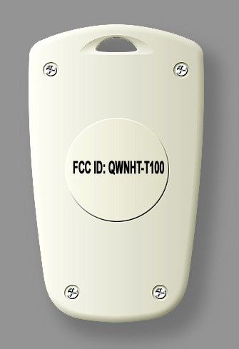
External Photos
Internal Photos
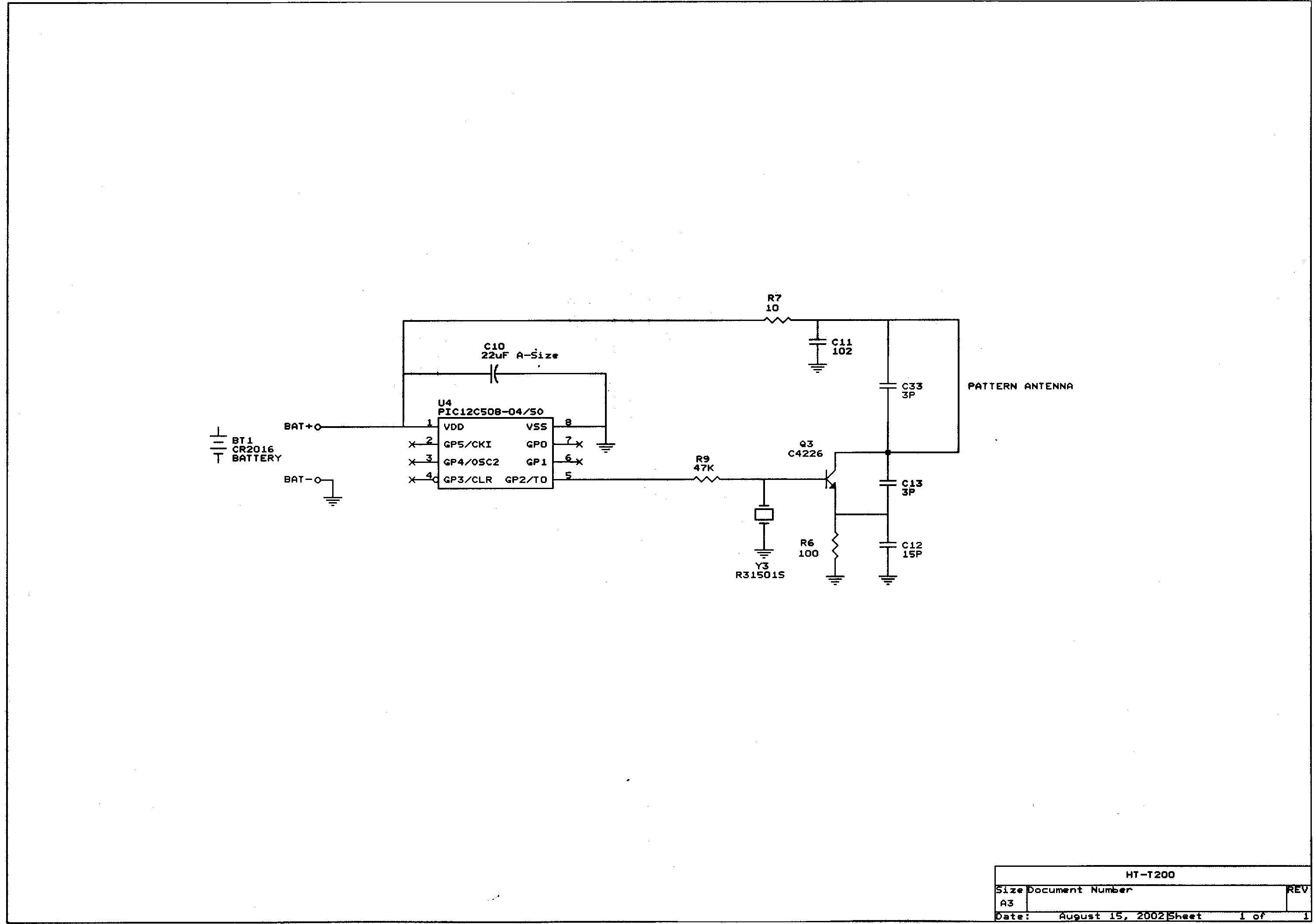
1) Micro Controller: U4 is 8 bit micro controller and regularly outputs ASK serial data. 2) Radio frequency(Oscillation) part: Q3 is transformed Colpitts oscillation circuit. It oscillate s fixed frequency of Y3’s Saw Resonator and the high frequency si gnal that gets Q3’s collector transmits through pattern antenna. R9 is Q3’s bias resistance. When serial data signal that em its from micro controller is +, Q3’s bias gets caught and oscillate s. And when data signal is -, it stops oscillating. So, according to the polarity of serial data signal that emits from micro co ntroller, it repeats and stops oscillating so it gives Q3 ASK modulation. R7 works as resistance that limits electric current in Q3’s collector. C11 bypasses high frequency noise that flows VCC to GND.
KTL Korea Testing Laboratory Page 1 of 14 TEST REPORT This test report only responds to the tested sample and shall not be reproduced except in full without written approval of the Korea Testing Laboratory. Tested and reported by Reviewed by Jeong-Min Kim, Senior Engineer Hee-Soo Kim , Telecommunication Team Manager KOREA TESTING LABORATORY FG101-01-02-00 222-13, Guro-Dong Guro-Gu Seoul Korea 152-053 http://www.ktl.re.kr Ref. Report No. 03-341-010 Name and address of the applicant Human Techtronics Co., Ltd. A-1717, Sam-Ho Company Bldg., 275-1, Yangjae-dong, Seocho-gu, Seoul, 137-940 Korea Standard / Test regulation FCC Part 15, Subpart C Test result Pass Incoming date : March 20, 2003 Test item(s) ; Low Power Transmitter (WatchCatch : Alarm System for missing child) Model/type ref. ; HT-T100 Manufacturer ; Human Techtronics Co., Ltd. Additional information ; -Required Authorization : Certification -FCC ID. : QWNHT-T100 Test date : March 25, 2003 Issue date : March 27, 2003 Ref. Report No. 03 - 341 – 010 Page 2 of 9 Korea Testing Laboratory Telecommunication Team 222-13, Guro3-dong, Guro-gu, Seoul Korea 152-848 TABLE OF CONTENTS I. GENERAL INFORMATION 3 1. Grantee’s Name and Mailing Address 2. Manufacturer's Name and Mailing Address 3. Equipment Descriptions 4. Rules and Regulations 5. Measuring Procedure 6. Place of Measurement 7. Date of Measurement . GENERAL REQUIREMENTS OF THE EUT 4 1. Labeling Requirement (Section 15.19) 2. Information to User (Sections 15.21) 3. Special Accessories (Section 15.27) . RADIATED EMISSION MEASUREMENT (Section 15.209) 5 1. Test Procedure 2. Photograph of the test configuration 3. Sample Calculation 4. Measurement Data 5. Reference Data . TEST EQUIPMENTS USED FOR MEASUREMENT 9 Ref. Report No. 03 - 341 – 010 Page 3 of 9 Korea Testing Laboratory Telecommunication Team 222-13, Guro3-dong, Guro-gu, Seoul Korea 152-848 . GENERAL INFORMATION 1. Grantee’s Name and : Human Techtronics Co., Ltd. Mailing Address A-1717, Sam-Ho Company Bldg., 275-1, Yangjae-dong, Seocho-gu, Seoul, 137-940, Korea 2. Manufacturer's Name and : Human Techtronics Co., Ltd. Mailing Address A-1717, Sam-Ho Company Bldg., 275-1, Yangjae-dong, Seocho-gu, Seoul, 137-940, Korea 3. Equipment Descriptions 3.1 Operating Frequency : 315.0 MHz 3.2 Type of Emission : ASK Modulated Signal 3.3 Power Supply : DC 3 V(Battery) 4. Rules and Regulations : FCC Part 15, Subpart C 5. Measuring Procedure : ANSI C63.4-2001 6. Place of Measurement : Absorber-lined Room (KTL) 7. Date of Measurement 7.1 Conducted Emission : Not Applicable 7.2 Radiated Emission : March 25, 2003 Ref. Report No. 03 - 341 – 010 Page 4 of 9 Korea Testing Laboratory Telecommunication Team 222-13, Guro3-dong, Guro-gu, Seoul Korea 152-848 . GENERAL REQUIREMENTS OF THE EUT 1. Labeling Requirement (Section 15.19) This device complies with Part 15 of the FCC Rules. Operation is subject to the following two conditions: (1) this device may not cause harmful interface, and (2) this device must accept any interference received, including interference that may cause undesired operation. 1.1 Location of Label : User’s Guide Manual 1.2 How Applied : Printed 2. Information to User (Section 15.21) The following or similar statements were provided in the manual for user instruction. Please refer page 3 of the attached manual for details. CAUTION : Any changes or modifications in construction of this device which are not expressly approved by the party responsible for compliance could void the user's authority to operate the equipment. 3. Special Accessories (Section 15.27) 3.1 Were the special Accessories provided? [ ] yes, [ x ] no 3.2 If yes, details for the special accessories are as follows : 3.3 If yes, were the appropriate instructions provided on the first page of the text concerned with the installation of the device? [ ] yes, [ ] no 3.4 Are these accessories provided of the type which can be readily obtained from multiple retail outlets ? [ ] yes, [ ] no And therefore does the manual specify what additional components or accessories are required to used in order to comply with the Rules? [ ] yes, [ ] no Ref. Report No. 03 - 341 – 010 Page 5 of 9 Korea Testing Laboratory Telecommunication Team 222-13, Guro3-dong, Guro-gu, Seoul Korea 152-848 . RADIATED EMISSION MEASUREMENT (Section 15.209) 1. Test Procedure 1.1 Preliminary Testing for Reference Preliminary testing was performed in a KTL absorber-lined room to determine the emission characteristics of the EUT. The EUT was placed on the wooden table which has dimensions of 0.8 meters in height, 1 meter in length and 1.5 meters in width. Receiving antenna (Biconical antenna : 30 to 300 MHz, Log-periodic antenna : 200 to 1000 MHz or Horn Antenna : 1 to 18 GHz) was placed at the distance of 1 meter from the EUT. An attempt was made to maximize the emission level with the various configurations of the EUT. Emission levels from the EUT with various configurations were examined on a spectrum analyzer connected with a RF amplifier and graphed by a plotter. 1.2 Final Radiated Emission Test at an Absorber-Lined Room The final measurement of radiated field strength was carried out in a KTL absorber-lined Room that was listed up at FCC according to the "Radiated Emissions Testing" procedure specified by ANSI C63.4. Based on the test results in preliminary test, measurement was made in same test set up and configuration with 3 orthogonal planes which produced maximum emission level. Receiving antenna was installed at 3-meter distance from the EUT, and was connected to an EMI receiver or spectrum analyzer with a RF amplifier. Turntable was rotated through 360 degrees and receiving antenna height was varied from 1 to 4 meters above the ground plane with horizontal and vertical polarization to read maximum emission level. If necessary, the radiated emission measurements could be performed at a closer distance than specified distance to ensure higher accuracy and their results were extrapolated to the spec…
Text truncated - open the document above for the full version.
Ref. Report No. 03 - 341 – 010 Page 7 of 9 Korea Testing Laboratory Telecommunication Team 222-13, Guro3-dong, Guro-gu, Seoul Korea 152-848 2. Photograph of the test configuration 3. Sample Calculation The emission level measured in decibels above one microvolt (dB) was converted into microvolt per meter (/m) as shown in following sample calculation. For example : Measured Value at 315.0 MHz 25.7 dB + Antenna Factor 14.0 dB/m + Cable Loss 3.3 dB Preamplifier 0.0 dB Distance Correction Factor * 0.0 dB ------------------------------------------------------------------------------------------- = Radiated Emission 43.0 dB/m ( = 141.3 /m ) * Extrapolated from the measured distance to the specified distance by an inverse linear distance extrapolation.
| # | Rule Parts | Frequency Range | Power Output |
|---|---|---|---|
| 1 | 15C | 315 MHz - 315 MHz | - |
Receiver
Equipment Class
CRR - Superregenerative Receiver