QWRMW-P150MSWIRELESS LAN GW(WIRELESS LAN USB DONGLE)
Maverick Systems, INC.
Click to zoom
Application Details
- Equipment Class
- DTS - Digital Transmission System
- Date of Grant
- Jun 03, 2010
- Application Purpose
- Original Equipment
- Date of Application
- Jun 03, 2010
- Equipment Note
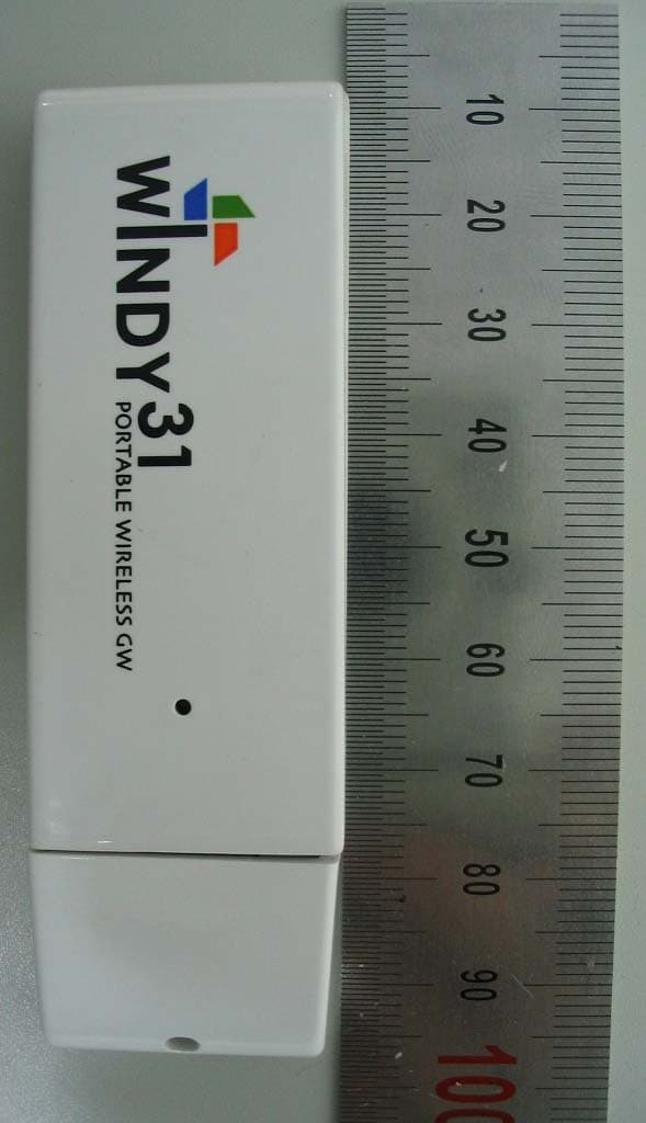
- WIRELESS LAN GW(WIRELESS LAN USB DONGLE)
- Frequency Range
- 2422.00000000 - 2452.00000000
- Company
- Maverick Systems, INC.
- Country
- South Korea
Documents & Files
Document Text
Text extracted from the exhibit documents filed with the FCC. Open a document above to read the original.
Users Manual
Please install on the PC which must be connected with internet. Introduction Windy31 Characteristics Scenario I/II 1. Features and configuration 1.1 Features 1.2 Configuration 1.3 Product Description 1.4 Installation Requirements 1.5 Structure Diagram of Windy31 2. Installation Windy31‐11n 2.1 before Installation 2.2 Windows 7 2.3 Windows VISTA 2.4 Windows XP 3. How to used Windy31‐11n 3.1 Windy31 Manager Setting 3.2 Wireless LAN Adapter Setting 4. Optional Configuration 4.1 Wireless LAN connection in Windows VISTA 4.2 Wireless LAN connection in Windows XP 4.3 Directly input IP Address 5. Trouble Shooting Contents 3 5 7 13 18 23 2 Introduction The USB‐type wireless portable gateway that combines a Wireless Router, Access Point(AP)and Wireless LAN Adapter all in one! All three of these functions allow the user to truly experience wireless freedom, as well as the convenience of portability. Because of its small size, users can virtually carry it wherever they go. Conveniently be plugged right into your PC, PDA, or laptop’s USB port 3‐in‐1 Wireless Broadband Router 1. Wireless Broadband Router The Windy31 is highly portable and user friendly, allowing the host to easily connect other surrounding Wi‐Fi enabled products, such as laptops, PDAs, and Wi‐Fi phones to the internet without the hassle of wires. 2. Wireless LAN Adapter The Windy31 can conveniently be plugged right into your computer, PDA, or laptop’s USB port. You can walk into any café, library, office, school, airport, or any other place that provides wireless internet service, and let the auto‐run installation program do the rest. 3. Wireless Access Point (WAP) The WINDY31 can wirelessly network up to 32 different clients together by being plugged into a single host computer. Manage all your local networks, easily share documents, and best of all, go wireless! WINDY31 Characteristics Auto‐installation without a CD Easy mode‐changing from LAN/AP/Router Convenient User‐Interface Windows Vista/7 Compatible! 3 Scenario I If you want to access the internet in a public area such as a Seminar, Trade Show, Library, Hotel, or Airport: ‐Existing: Only a wireless internet service subscriber can use the internet ‐Windy31: Plug the Windy31 into any computer that is connected to the internet, and you can use the internet service through your laptop Scenario II If you want to share your internet connection with friends or co‐ workers without paying for each additional line at a wireless service provided from Airport, Hotel, Conference room, Trade show, etc. ‐Existing: No choice for non‐subscribers. You have to pay for each user. ‐Windy31: Plug the Windy31 into the subscriber’s computer and share the connection with friends and co‐workers at no additional cost. Client 2Client 1Client 3 Internet ISP) WiFi‐Pone WINDY31 Client 3 Internet(ISP) Router Hub Client 1 WiFi‐Pone Client 2 HOST PC Windy31 typical Configuration(At Home or Office) 4 1.1 Features Convenient to use anywhere and anytime ‐Portable, slim and compact design to fit in one hand (USB memory stick size) ‐The only thing required is internet connected computer, easy and fast internet connection sharing Fast installation and easy setting ‐Connect Windy31 into computer for auto installation of driver and utility programs (Separate installation CD and driver not necessary) ‐Easy GUI‐type setting screen Speed ‐Support Wireless 802.11b(11Mbps) speed 802.11g(54Mbps) speed 802.11n(Max.150Mbps) speed Security ‐Access control with WEP(64,128 bit) / WPA‐PSK / WPA2‐PSK(ASE) and MAC address 1.2 Configuration Please check Windy31 product configurations as shown below. Please contact the seller you purchased from immediately if contents of product is damaged or missing. 1.3 Product Description USB type Broadband Router Quick install Guide 1. Features and configuration 5 1.4 Installation Requirements Before installing Windy31, Please check whether your computer configuration matches the requirements shown below. ‐Intel Pentium IV or above ‐512M bytes system memory or above ‐Windows XP/VISTA/7 Operating Systems ( Support auto‐installation for Windows XP or above) ‐USB 1.1 or USB 2.0 ‐Requires more than 30M bytes of usable hard disk space Internet (ISP) •x‐DSL Modem •Cable Modem •Exclusive Line •PPP •Nespot •HSDPA •WIBRO •Auto Installation •Dynamic Loading PSP Nintendo PDA/PMP PC/Laptop i‐phone up to 32 clients Wi‐Fi Phone 6 1.5 Configuration 6 2.1 Usage Precautions Checklist before installing 1. Please be sure that Windy31 must be inserted to a computer which is connected to Internet. 2. Computer to be installed with Windy31 must have more than one LAN Adapter. 3. Please check your computer for Virus and Spyware, before installation. Some Viruses and Spywares may interfere with automatic installation of Widny31 driver and utility programs Installation 1) Insert Windy31 into USB port of Laptop or Desktop PC and program will automatically run as shown below. 2) After program installation, the following screen will appear one after another in the right‐side of Windows Task bar, showing that the USB device acknowledges and is installing Windy31. 2.2 Windows 7 2. Installation Windy31 7 2) Please wait until “Windy31 Gateway Manager” window appears, “Windy31 setting in‐ progress " and "setting complete" windows are displayed as shown below. This process will take some minutes as it is installing the Windy31 Gateway. (Installation time may differ according to computer configuration) 3) In Step 3, After “Program has been successfully installed“ appears, click “OK”. Then, Windy31 has completed installation. Connection method may differ according to Wireless LAN device, please refer to Wireless LAN usage method. (For wireless device usage method, please refer to wireless device product manual or please contact the provider.) During installation, Windows Security Alert may display “Keep blocking” & “Unlock” pop‐ up for security, please select the button “Unlock”. (If you select “Keep blocking” bloc…
Text truncated - open the document above for the full version.
Cover Letter(s)
Tel. : 82-70-7018-0250 Fax. : 82-2-2082-1590 May 26, 2010 Federal Communications Commission Authorization and Evaluation Division Confidentiality Request regarding application for certification of FCC ID: QWRMW-P150MS Pursuant to Sections 0.457 and 0.459 of the Commission’s Rules, we hereby request confidential treatment of information accompanying this application as outlined below: Exhibit Type File Name Part List CONF APPENDIX – MW-P150MS - Part List.PDF Schematics Diagram(s) CONF APPENDIX - MW-P150MS – Schemetics.PDF Block diagram CONF APPENDIX - MW-P150MS – Block diagramPDF The above materials contain trade secrets and proprietary information not customarily released to the public. The public disclosure of these materials may be harmful to the applicant and provide unjustified benefits to its competitors. The applicant understands that pursuant to Section 0.457 of the Rules, disclosure of this application and all accompanying documentation will not be made before the date of the Grant for this application. Sincerely, Maverick Systems, INC. young-youl choi / CEO
External Photos
EUT External Photographs
ID Label/Location Info
www.kes.co.kr EUT label and Location
Internal Photos
EUT Internal Photographs
Operational Description
RT2720 2.4 GHz Transceivers Datasheet Revision January 20, 2009 DSR2720_V3.0_012009 -1- Form No.:QS-073-F02 Rev.:1 Kept by: DCC Ret. Time: 5 Years Application IEEE802.11 b/g Wireless Local Area Networks • TDMA Packet Protocol Radios IEEE802.11n Wireless Local Area Networks • 2.4GHz ISM Wireless System RT2720 is a monolithic SiGe RF IC that integrates half- duplex direct-conversion radio transceivers designed for IEEE802.11 b/g/n WLAN systems or other wireless LAN applications operating in 2.4GHz (low-band) ISM bands. The IC has one transmit channel and two concurrent receive channels. The receivers achieve low noise figure, high input sensitivity, high linearity, and high output power while consuming low dc power. The two receive channels are designed to improve robustness and to receive two data streams during receive operation. Each receive path features a gain selectable, low-noise amplifiers (LNA), followed by RF-to-baseband I/Q demodulators, discrete-step variable-gain amplifiers and integrated channel- selection filters. The transmit chain includes integrated reconstruction filters, a baseband-to-RF I/Q modulator, discrete-step variable-gain amplifiers for power-level control, and pre-drivers for external power amplifiers. The modulator and demodulator are driven by internal VCO. The VCO is phase-locked by an internal 3-wire-interfaced PLL. The bandwidth of the integrated channel-selection filters and the reconstruction filters can be programmed to narrow- band (10MHz) and wide- band (20MHz). Their bandwidth is calibrated by an internal autonomous calibration circuit. To help IQ mismatch calibration, a baseband transmit-to-receive loopback feature is provided. A crystal oscillator using external crystal and three low dropout regulators (LDO) are also integrated. The RT2720 is housed in a 68-pin 8x8mm 2 leadless QFN package well suited for PCMCIA, MiniPCI, PCI, USB boards or embedded applications. It is designed to work seamlessly with RT2860 and RT2880 baseband/Mac IC. Features ♦ A single-chip transceiver ♦ 2.4 GHz bands ♦ Low noise figure ♦ High linearity ♦ Low power consumption ♦ Integrated channel-selection filters ♦ Integrated reconstruction filters ♦ Power management/standby mode ♦ Integrated low dropout regulators ♦ Single supply 3.0 to 3.6V operation Rx • Icc.........................................................................129 mA • Receiver Sensitivity (54Mbps)........................ -73 dBm •Receiver DSB Noise Figure...................................... 6 dB •Input IP3 (High Gain) ........................................-20 dBm •Input IP3 (Low Gain) ......................................... 12 dBm •Input P1dB (High Gain)..................................... -30 dBm •Input P1dB (Low Gain)......................................... 2 dBm • VGA Gain Control Range..................................... 62 dB Tx • Icc......................................................................... 104mA • Output Power (OFDM)........................................ 6 dBm • Output Noise Floor......................................-141dBm/Hz • Output P1dB........................................................14 dBm • VGA Gain Control Range...................................... 15 dB Sleep •Icc..............................................................................<1uA Order Information Ralink Technology, Corp. (Taiwan) 5th F. No. 36,Taiyuan St, Jhubei City, Hsin-Chu, Taiwan, R.O.C. Tel: 886-3-560-0868 Fax: 886-3-560-0818 Ralink Technology, Corp. (USA) 20833 Stevens Creek Blvd., Suite 200 Cupertino, CA95014 Tel: (408) 725-8070 Fax: (408)725-8069 http://www.ralinktech.com Part Number Temp Range Package RT2720L -10~85 0 C 68Ld QFN RT2720 2.4 GHz Transceivers Datasheet Revision January 20, 2009 DSR2720_V3.0_012009 -2- Form No.:QS-073-F02 Rev.:1 Kept by: DCC Ret. Time: 5 Years Functional Block Diagram RF_PE TR_PE LE Data0 CLK Data1 RF CTL PLL RF VCO 0 o 90 o LDOs Cystal Oscillator AMP VGA VGA LNA VGA LNA RFin 1 RFout 0 RFin 0 I_Out 1 Q_Out 1 I_Out 0 Q_Out 0 I_In 0 Q_In 0 RT2720 2.4 GHz Transceivers Datasheet Revision January 20, 2009 DSR2720_V3.0_012009 -3- Form No.:QS-073-F02 Rev.:1 Kept by: DCC Ret. Time: 5 Years Table of Content 1. Pin Description ........................................................................................................................................... 4 1.1 Pinout of RT2820 QFN76 9x9mm 2 ..................................................................................................... 4 1.2 Pin Description of RT2820 .................................................................................................................... 5 2. Maximum Ratings and Operating Conditions .............................................................................................. 7 2.1 Absolute Maximum Ratings ................................................................................................................. 7 2.2 Thermal Information ............................................................................................................................ 7 2.3 Operating Conditions ........................................................................................................................... 7 2.4 DC Electrical Characteristics ................................................................................................................. 7 2.5 AC Electrical Characteristics ................................................................................................................. 8 2.5.1 Receiver (each channel) ................................................................................................................. 8 2.5.2 Baseband Receive Filter and Output Buffer (common for low-band and high-band receivers) ........ 8 2.5.3 Transmitter (each channel) ............................................................................................................ 9 2.5.4 Baseband Transmit Filter (common for both lo…
Text truncated - open the document above for the full version.
Operational Description
G G a a i i n n F F o o r r c c e e T T e e c c h h n n o o l l o o g g y y C C o o . . , , L L t t d d 嘉光科技股份有限公司 R&D / PE / QC /PURCHASE / VENDOR APP.NO.: 承認書 A A P P P P R R O O V V A A L L S S H H E E E E T T 品 名: Chip Antenna MODEL NAME 料 號: AT5020-E3R0HBAT/LF PAT NUMBER 5.0*2.0mm/2.4G 客戶名稱: 訊舟科技股份有限公司 CUSTOMER 供 應 商: 嘉光科技股份有限公司 VENDOR 承認料號: Approve P/N 使用機種: MODEL 聯 絡 人: 李 丞 皓 聯絡電話: +886-2-2880-1838 附 件: ACCESSORIES ■規格書 ■樣品 SPECIFICATION SAMPLE ■圖樣 □檢驗報告 DRAWING TEST REPORT 認可狀況: (APPROVED STATUS) ACX Advanced Ceramic X AT5020 Series Multilayer Chip Antenna Features Monolithic SMD with small, low-profile and light-weight type. Wide bandwidth Applications 2.4GHz WLAN, Home RF, Bluetooth Modules, etc. Specifications Part Number Frequency Range (MHz) Peak Gain (dBi typ.) Average Gain (dBi typ.) VSWR Impedance AT5020 -E3R0HBA_ 2400~2500 0dBi (XZ-V)-1.5dBi (XZ-V)2 max. 50 Ω Q’ty/Reel (pcs) : 2,000 pcs Operating Temperature Range : -40 ~ +85 o C Storage Temperature Range : -40 ~ +85 o C Power Capacity : 3W max. Part Number AT 5020 - E 3R0 HBA i ghfe dc c Type AT : Antenna d Dimensions ( L × W ) 5.0× 2.0 mm e Material Code E f Frequency Range 3R0=3000MHz g Specification Code HBA h Packaging T: Tape & Reel B: Bulk i Soldering =lead-containing /LF=lead-free Terminal Configuration f A C X e No. Terminal NameNo. Terminal Name c Feeding Point e NC d NC f NC d c ACX Advanced Ceramic X Dimensions and Recommended PC Board Pattern Unit : mm L a A C X W L1 T Top view Side view Bottom view W1 Mark L W L1 W1 T a Dimensions 5.00.2 2.00.2 2.60.2 0.50.2 2.0+ 0.1/-0.2 0.50.3 (a) Without Matching Circuits (Unit in mm) (b) With Matching Circuits *Line width should be designed to match 50Ω characteristic impedance, depending on PCB (Matching circuit and component values will be different, depending on PCB layout) 1.03 2.8 1 0.7 1 1 0.7 0.82 0.7 1 2 2 8 3.86 0 Ohm 0.7 A C X 2.8 1 1 0.7 1 0.7 1.03 0.7 0.7 0.82 1 2 2 A C X 3.3 nH 3.86 1.5 nH 8 ACX material and thickness. Advanced Ceramic X Typical Electrical Characteristics (T=25 o C) Test Board (Unit in mm) 3.86 Ground 8 No Ground Antenna 20 40 Return Loss(with matching) ACX Advanced Ceramic X Radiation Patterns XZ cut @2.45GHz Vertical Horizontal YZ cut @2.45GHz Vertical Horizontal XZ-V/XZ-H YZ-V/YZ-H XY cut @2.45GHz Vertical Horizontal Z 270 o 0 o 90 o X Y XY-cut scanning direction Y 270 o 0 o 90 o X Z XZ-cut scanning direction X 270 0 o 90 o Z Y YZ-cut scanning direction Advanced Ceramic X Corp. 16 Tzu Chiang Road, Hsinchu Industrial District Hsinchu Hsien 303, Taiwan TEL:886-3-5987008 FAX:886-3-5987001 E-mail: [email protected] http://www.acxc.com.tw 180 180 180 o XY-V/XY-H ACX Adv anced Ceram ic X Soldering Conditions Typical Soldering Profile for Lead-free Process Flow Soldering : Reflow Soldering : T e m p erature ( o C) 20s. 230 o C 180 o C 260C 5s, max. Time (s.) 60s, min. Pre-heating 30s. 230 o C 180 o C 250 o C 10s, max. Time (s.) 60s, min. Pre-heating T e m p erature ( o C) Notes The contents of this data sheet are subject to change without notice. Please confirm the specifications and delivery conditions when placing your order. Sample Description : Style/Item No. : Buyer/Order No. : Sample Receiving Date : Testing Period : ============================================================================================ Test Requested : Test Method: (1) (2) (3) (4) (5) Test Result(s) : Test Report No. : CE/2007/C1026Date : 2007/12/12Page : 1 of 5 2007/12/05 *CE/2007/C1026* MULTILAYER LTCC-E COMPONENTS ADVANCED CERAMIC X (ACX) CORPORATION 16 TZU CHIANG ROAD, HSINCHU INDUSTRIAL DISTRICT, HSINCHU HSIEN, TAIWAN 303 Please refer to next page(s). The following sample(s) was/were submitted and identified by/on behalf of the client as : Determination of PBB and PBDE by GC/MS. Determination of Hexavalent Chromium for non-metallic samples by UV/Vis Spectrometry. Determination of Cadmium by ICP-AES. In accordance with the RoHS Directive 2002/95/EC, and its amendment directives. Determination of Lead by ICP-AES. Determination of Mercury by ICP-AES. With reference to IEC 62321, Ed.1 111/54/CDV Procedures for the Determination of Levels of Regulated Substances in Electrotechnical Products. LOCAL COMPANY OR USA COMPANY 2007/12/05 TO 2007/12/12 AD SERIES, AM SERIES, AT SERIES, AW SERIES, BD SERIES, BF SERIES, BL SERIES, BM SERIES, CD SERIES, CF SERIES, CP SERIES, DM SERIES, DP SERIES, DS SERIES, FA SERIES, FB SERIES, HI SERIES, HF SERIES, LF SERIES, LF SERIES, NF SERIES, TS SERIES, LTCC SUBSTRATES, BCM2307 The content of this PDF file is in accordance with the original issued reports for reference only. This Test Report cannot be reproduced, except in full, without prior written permission of the Company SGS TAIWAN LIMITED NO. 136-1, Wu Kung Road, WuKu Industrial Zone, Taipei county, Taiwan. t(886-2) 22993939 f(886-2) 2299-3237 www.sgs.com.tw Result No.1 n.d.2 192 n.d.2 n.d.2 n.d.- n.d.5 n.d.5 n.d.5 n.d.5 n.d.5 n.d.5 n.d.5 n.d.5 n.d.5 n.d.5 n.d.- n.d.5 n.d.5 n.d.5 n.d.5 n.d.5 n.d.5 n.d.5 n.d.5 n.d.5 n.d.5 n.d.- 16 TZU CHIANG ROAD, HSINCHU INDUSTRIAL DISTRICT, HSINCHU HSIEN, TAIWAN 303 Method (Refer to) MDL Hexabromobiphenyl ether TEST PART DESCRIPTION: Octabromobiphenyl ether Test Report No. : CE/2007/C1026Date : 2007/12/12Page : 2 of 5 ADVANCED CERAMIC X (ACX) CORPORATION*CE/2007/C1026* NO.1:MULTILAYER LTCC-E COMPONENTS 4. According to 2005/717/EC DecaBDE is exempt. 5. "-" = Not Regulated Note:1. mg/kg = ppm 2. n.d. = Not Detected 3. MDL = Method Detection Limit Dibromobiphenyl Nonabromobiphenyl ether Sum of PBDEs (Mono to Deca) Decabromobiphenyl ether Decabromobiphenyl Pentabromobiphenyl Heptabromobiphenyl ether Pentabromobiphenyl ether Nonabromobiphenyl Tetrabromobiphenyl ether Monobromobiphenyl ether Tetrabromobiphenyl Hexabromobiphenyl Dibromobiphenyl ether Tribromobiphenyl ether Octabromobiphenyl Sum of PBBs (1) Monobromobiphenyl Tribromobiphenyl (2) Test Item (s): Cadmium (Cd) Hexavalent Chromium Cr(VI) by alkaline extraction Test results by chem…
Text truncated - open the document above for the full version.
RF Exposure Info
www.kes.co.kr Page 1 of 2 RF EXPOSURE EVALUATION Applicant : Maverick Systems, Inc. Applicant Address No.511 SeochoWorld Officetel, 1355-3, Seocho-Dong, Seocho-Gu Seoul , Korea Kind of Product : Wireless LAN GW(Wireless LAN USB Dongle) Equipment model name : MW-P150MS Antenna type : Chip antenna Gain: 0dBi Frequency Range : 802.11b/g/n(HT20) : 2412 ~ 2472 MHz : 802.11n(HT40) : 2422 ~ 2462 MHz Number of channels : 802.11b/g/n(HT20) : 11Channels : 802.11n(HT40) : 7Channels Channel Spacing : 5 MHz www.kes.co.kr Page 2 of 2 ** MPE Calculations ** The EUT will only be used with a separation of 20 centimeters or greater between the antenna and the body of the user. The MPE calculation for this exposure is shown below. The peak radiated output power (EIRP) is calculated as follows: EIRP = P + G EIRP = 9.24 dBm Where, P = Power input to the antenna (mW) G = Power gain of the antenna (dBi) The numeric gain(G) of the antenna with a gain specified in dB is determined by: G = Log -1 (dB antenna gain / 10) G = Log -1 (0/ 10) G = 1 Power density at the specific separation: S = PG/(4R 2 π) S = (8.39 * 1 / (4 * 20 2 * π) S = 0.0017 mW/cm 2 Where, S = Maximum power density (mW/cm 2 ) P = Power input to the antenna (mW) G = Numeric power gain of the antenna R = Distance to the center of the radiation of the antenna (20cm = limit for MPE) The Maximum permissible exposure (MPE) for the general population is 1 mW/cm 2 . The power density at 20cm does not exceed the 1 mW/cm 2 limit. Estimated safe separation: R = √(PG / 4π) R = √(8.39 * 1/ 4π) R = 0.82 cm Where, P = Power input to the antenna (mW) G = Numeric power gain of the antenna R = Distance to the center of the radiation of the antenna (20cm = limit for MPE)
Test Report
www.kes.co.kr Te s t Re p o r t N o. : TK-FR10025 Model No: MW-P150MS Applicant: Maverick Systems, Inc. Page 1 of 65 This Report shall not be reproduced except in full without the written approval of THRU-KES co.,Ltd. TEST REPORT For FCC Test Report No. : TK-FR10025 Date of Issue : 06/01/2010 Description of Product : Wireless LAN GW(Wireless LAN USB Dongle) FCC ID : QWRMW-P150MS Model No. : MW-P150MS Applicant : Maverick Systems, Inc. No.511 SeochoWorld Officetel, 1355-3, Seocho-Dong, Seocho-Gu Seoul , Korea Manufacturer : Maverick Systems, Inc. No.511 SeochoWorld Officetel, 1355-3, Seocho-Dong, Seocho-Gu Seoul , Korea Standards : FCC Part 15 Subpart C §15.247 Test Date : 05/18/2009 ~ 06/01/2010 Test Results : PASS FAIL The test results relate only to the items tested. Tested by: Reviewed by: Kyu-Chul Shin KT Kang Test Engineer Technical Manager Date:06/01/2010 Date: 06/01/2010 THRU-KES CO.,LTD. 477-6, Hager-Ri, Yoju-Up, Yoju-Gun Kyunggi-Do,469-803, Korea Tel: +82-31-425-6200 / Fax: +82-31-424-0450 www.kes.co.kr Te s t Re p o r t N o. : TK-FR10025 Model No: MW-P150MS Applicant: Maverick Systems, Inc. Page 2 of 65 This Report shall not be reproduced except in full without the written approval of THRU-KES co.,Ltd. TABLE OF CONTENTS 1.0 General Product Description ...............................................................................3 1.1 Tested Frequency .............................................................................................3 1.2 Model Differences .............................................................................................4 1.3 Device Modifications .........................................................................................4 1.4 Peripheral Devices ............................................................................................4 1.5 Calibration Details of Equipment Used for Measurement .........................................5 1.6 Test Facility......................................................................................................5 1.7 Laboratory Accreditations and Listings .................................................................5 2.0 Summary of tests .............................................................................................6 2.1 Technical Characteristic Test .....................................................................................7 2.1.1 6dB Bandwidth ...........................................................................................7 2.1.2 Maximum peak Conducted Output Power...................................................... 17 2.1.3 Power Spectral Density .............................................................................. 27 2.1.4 Band - edge ............................................................................................. 37 2.1.5 Field Strength of Emissions ........................................................................ 54 2.1.6 AC Conducted Emissions............................................................................ 62 APPENDIX A – Test Equipment Used For Tests ................................................................ 65 www.kes.co.kr Te s t Re p o r t N o. : TK-FR10025 Model No: MW-P150MS Applicant: Maverick Systems, Inc. Page 3 of 65 This Report shall not be reproduced except in full without the written approval of THRU-KES co.,Ltd. 1.0 General Product Description Equipment model name : MW-P150MS Serial number : Prototype EUT condition : Pre-production, not damaged Antenna type : Chip antenna Gain 0dBi Frequency Range : 802.11b/g/n(HT20) :2412MHz ~ 2472MHz : 802.11n(HT40) :2422MHz ~ 2462MHz RF output power : 802.11b: 9.24 dBm Peak Conducted : 802.11g: 7.93 dBm Peak Conducted : 802.11n(HT20): 7.91 dBm Peak Conducted : 802.11n(HT40): 7.43 dBm Peak Conducted Number of channels : 802.11b/g/n(HT20): 11 , 802.11n(HT40) : 7 Channel Spacing : 5 MHz Transfer Rate : 11/5.5/2/1Mbps for 802.11b : 54/48/36/24/18/12/9/6Mbps for 802.11g : 65/58.5/52/36/26/19.5/13/6.5Mbps for 802.11n(HT20) : 130/117/104/78/52/39/26/13Mbps for 802.11n(HT40) Type of Modulation : CCK, DQPSK, DBPSK for DSSS : 64QAM, 16QAM, QPSK, BPSK for OFDM Power Source : DC 5V 1.1 Tested Frequency 802.11b/g/n(HT20) LOW MID HIGH Frequency (MHz) 2412 2437 2462 802.11n(HT40) LOW MID HIGH Frequency (MHz) 2422 2437 2452 www.kes.co.kr Te s t Re p o r t N o. : TK-FR10025 Model No: MW-P150MS Applicant: Maverick Systems, Inc. Page 4 of 65 This Report shall not be reproduced except in full without the written approval of THRU-KES co.,Ltd. 1.2 Model Differences Not applicable 1.3 Device Modifications The following modifications were necessary for compliance: Not applicable 1.4 Peripheral Devices Device Manufacturer Model No. Serial No. FCC ID or DoC EUT Maverick Systems, Inc. MW-P150MS - - Notebook F U J I T S U L T DLIFEBOOK S-5582434230343466 DoC www.kes.co.kr Te s t Re p o r t N o. : TK-FR10025 Model No: MW-P150MS Applicant: Maverick Systems, Inc. Page 5 of 65 This Report shall not be reproduced except in full without the written approval of THRU-KES co.,Ltd. 1.5 Calibration Details of Equipment Used for Measurement Test equipment and test accessories are calibrated on regular basis. The maximum time between calibrations is one year or what is recommended by the manufacturer, whichever is less. All test equipment calibrations are traceable to the Korea Research Institute of Standards and Science (KRISS), therefore, all test data recorded in this report is traceable to KRISS. 1.6 Test Facility 477-6, Hager-Ri, Yoju-Up, Yoju-Gun Kyunggi-Do,469-803, Korea 1.7 Laboratory Accreditations and Listings Country Agency Scope of Accreditation Logo USA FCC 3 & 10 meter Open Area Test Sites and one conducted site to perform FCC Part 15/18 measurements. 93250 KOREA KCC EMI (10 meter Open Area Test Site and two conducted sites) EMS (ESD, RS, EFT/Burst, Surge, CS, Magnetic, Dips and interruptions) KR100 www.kes.co.kr Te s t Re p o r t N o. : TK-FR10025 Model No: MW-P150MS …
Text truncated - open the document above for the full version.
Test Setup Photos
www.kes.co.kr Test Setup Photos and Configuration Conducted Voltage Emissions www.kes.co.kr Radiated Electric Field Emissions
Contact Information
Applicant
Young Youl Choi(President)
Test Firm
KES Co., LtdInsung Ryu
Technical Specifications
| # | Rule Parts | Frequency Range | Power Output |
|---|---|---|---|
| 2 | 15C | 2.42 GHz - 2.45 GHz | 5.50 mW |
Other Applications from Maverick Systems, INC.
QWRMWP54SS
Oct 25, 2007801.11b/g WLAN USB Adapter
Equipment Class
DTS - Digital Transmission System
QWRNASDISK1000
Feb 19, 2003Internet Storage Device
Equipment Class
JBP - Part 15 Class B Computing Device Peripheral