QXDMIV30Shipboum Automatic Identification System (AIS)
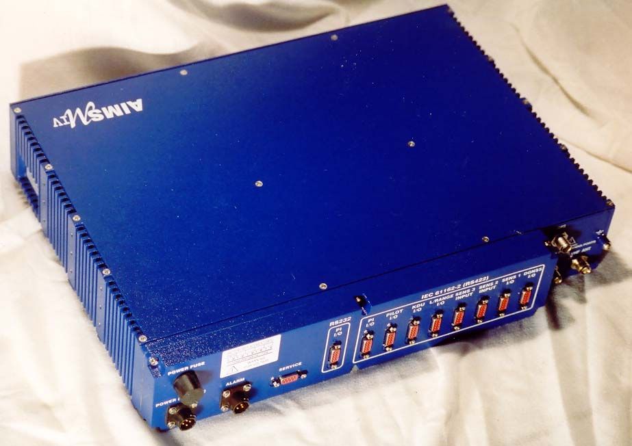
Marine Data Systems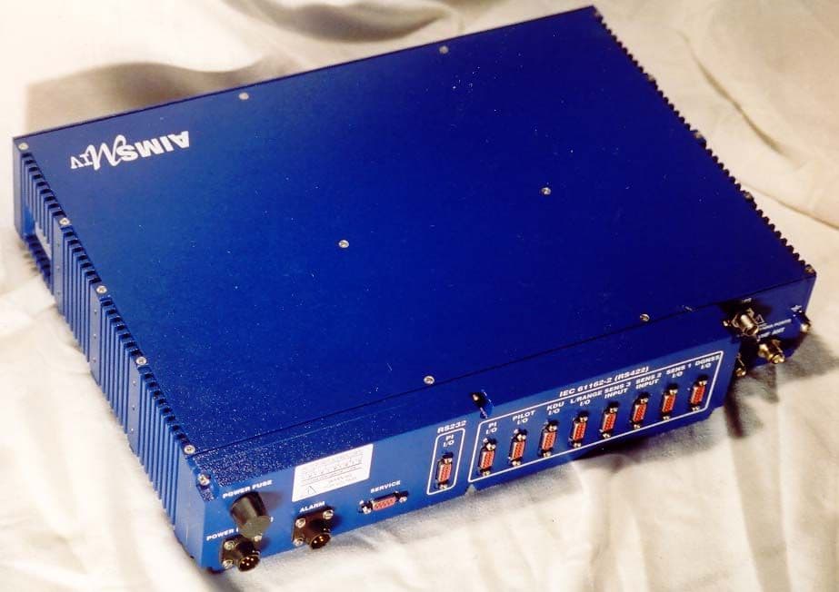
Click to zoom
Application Details
- Equipment Class
- AIS - Automatic Identification Systems
- Date of Grant
- Mar 24, 2003
- Application Purpose
- Original Equipment
- Date of Application
- Feb 27, 2003
- Equipment Note
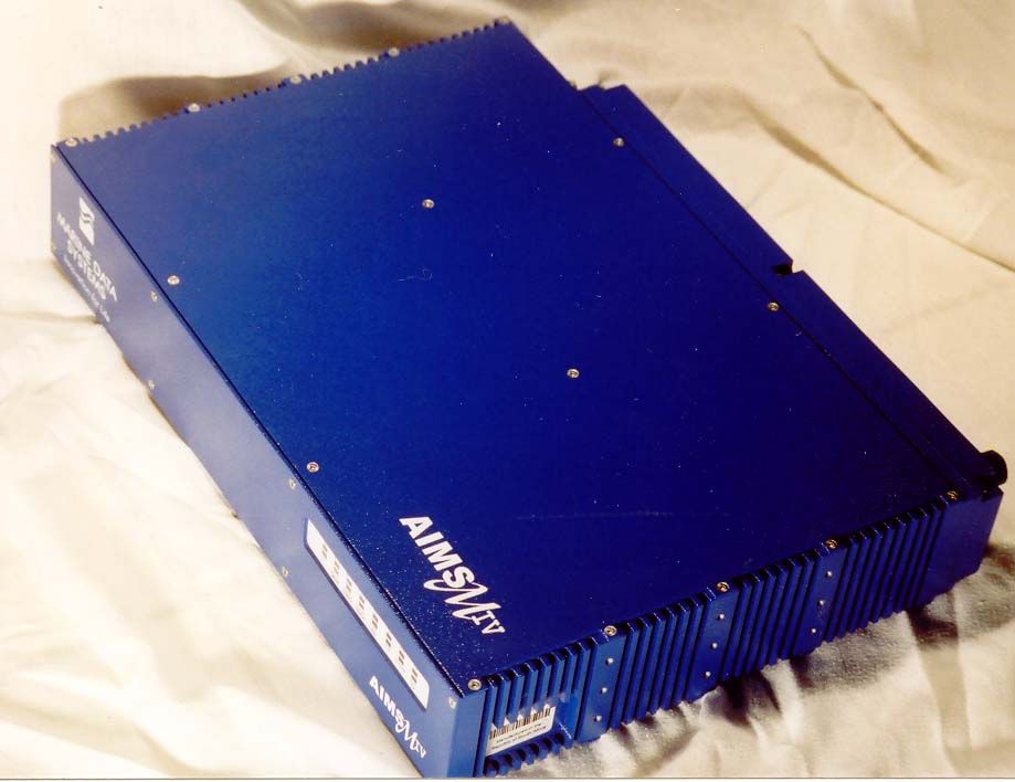
- Shipboum Automatic Identification System (AIS)
- Frequency Range
- 156.52500000 - 156.52500000
- Company
- Marine Data Systems
- Country
- South Africa
Documents & Files
Document Text
Text extracted from the exhibit documents filed with the FCC. Open a document above to read the original.
Users Manual
AIMS MIV AIS 1371-1 Technology TECHNICAL USER MANUAL Revision 01 IMPORTANT WARNINGS DANGER: HIGH VOLTAGE! RISK OF ELECTRICAL SHOCK! This unit has a high voltage source inside. Disconnect from the power before opening. DO NOT remove the covers while the unit is switched on. 5 Volt electrical power on GPS and DBR (when fitted) antenna ports. NOTICE Compass safe distance is 1 meter. NOTICE No user serviceable parts inside, servicing only by properly qualified and certified technical staff. NOTICE The GPS module uses a back-up battery to ensure quick start-up of the GPS unit. This battery must be replaced every 5 years. NOTICE This manual is for informational use only, and may be changed without notice. This manual should not be construed as a commitment of Marine Data Systems. Under no circumstances does Marine Data Systems assume any responsibility or liability for any errors or inaccuracies that may appear in this document. The equipment should only be used for the purposes intended by the manufacturer; any deviation from this will void the warranty of the product. Document No. 1101-0010-AA-00-TM Issue: 10 Marine Data Systems (Pty.) Ltd. AIMS MIV ManualTable of Contents AIS3 TABLE OF CONTENTS 1. INTRODUCTION..............................................................................................7 1.1.Automatic Identification System (AIS) Overview.........................................7 1.2.AIS Unit Overview......................................................................................7 1.2.1.Data Interfaces..............................................................................................................7 1.2.2.RF Interfaces.................................................................................................................8 1.2.3.Technical data...............................................................................................................8 1.2.4.Dimensions And Weights..............................................................................................8 1.2.5.Receiver Default Frequencies.......................................................................................9 1.2.6.AIS Receivers...............................................................................................................9 1.2.7.AIS Transmitter.............................................................................................................9 1.2.8.DSC Receiver................................................................................................................9 1.2.9.Alarm Relay.................................................................................................................10 1.2.10.Compass Safe Distance..............................................................................................10 1.2.11.Navigation Specifications (Internal Sensors)..............................................................10 1.2.12.Listener and Talker Specifications..............................................................................11 2. INSTALLATION.............................................................................................13 2.1.Unpacking the Unit....................................................................................13 2.2.Mounting the Unit......................................................................................13 2.3.External Interfaces....................................................................................15 2.4.Grounding the AIS unit..............................................................................16 2.5.AIS VHF Antenna installation....................................................................17 2.5.1Alternative VHF antenna installation options...................................................................18 2.5.1.1.Option 1..............................................................................................................................18 2.5.1.2.Option 2..............................................................................................................................19 2.5.2.Minimising Interference: Additional Guidelines...........................................................19 2.6.AIS GPS Antenna Installation...................................................................19 2.7.Cable and Plug Connection Specifications................................................20 2.7.1.RF Cables...................................................................................................................20 2.7.1.1.GPS Antenna (Cable type E)...............................................................................................20 2.7.1.2.VHF Antenna (Cable type F)...............................................................................................21 2.7.1.3.DBR Antenna (Cable Type L)..............................................................................................21 2.7.2.Data Interface Connections.........................................................................................21 2.7.2.1.Presentation Interface.........................................................................................................21 2.7.2.2.Pilot Port.............................................................................................................................23 2.7.2.3.KDU (Keyboard Display Unit)..............................................................................................23 2.7.2.4.Long-Range Communication Port (L/RANGE I/O)...............................................................24 2.7.2.5.Sensor Input Ports (SENS 1, SENS 2, SENS 3).................................................................24 2.7.2.6.DGNSS Port........................................................................................................................25 2.7.2.7.Service Port....................................................................................................…
Text truncated - open the document above for the full version.
Attestation Statements
WAYNE LANGSTON, INC. P.O. Box 1377, League City, TX 77574-1377 Phone: 281-337-6785; Fax: 281-337-7217; Email: [email protected] www.waynelangstoninc.com March 20, 2003 Confidentiality Request Letter FCC ID: QXDMIV30 Applicant: Marine Data Systems Correspondence Reference Number: 24945 731 Confirmation Number: EA448260 RE: Request of Confidentiality As agent for and on behalf of Marine Data Systems, and Pursuant to Sections 0.457(d)(1)(ii) and 0.459 of the Commission’s Rules, The applicant hereby requests confidential treatment of information accompanying as outlined below: Due to the nature of the product, the identification of all information for which confidential treatment is sought: Schematics Parts List, etc. If you should have further questions or problems with this request, please contact me at (office 281-337- 6785 or Cell: 281-731-4895). Respectfully, Wayne Langston Agent
Attestation Statements
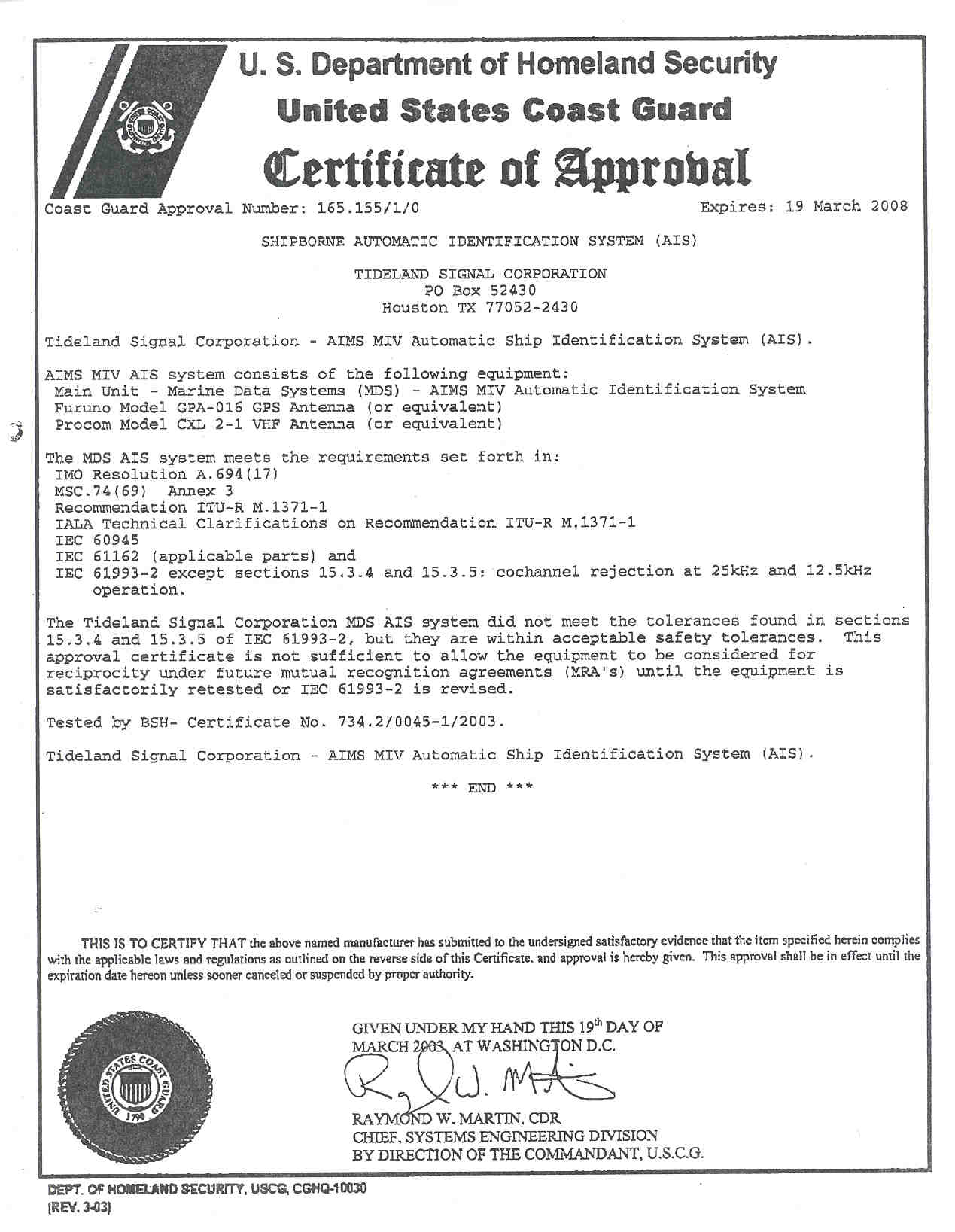
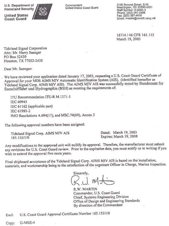
WAYNE LANGSTON, INC. P.O. Box 1377, League City, TX 77574-1377 Phone: 281-337-6785; Fax: 281-337-7217; Email: [email protected] www.waynelangstoninc.com March 20, 2003 Mr. Andy Leimer Federal Communication Commission RE: FCC ID: QXDMIV30 Applicant: Marine Data Systems Correspondence Reference Number: 24945 731 Confirmation Number: EA448260 Dear Mr. Leimer, This is in response to our email dated March 14, 2003 with regard to the above application. Please note the following information. 1). A revised Request for Confidentiality is provided under the file name: mds revised request for confidentiality 2). A copy of the operation description provided by the applicant is attached for your review. File name: mds operational information 3). The non-compliance for the receiver is due to the receiver being an analog design. While in theory it may be possible to design an analog receiver to meet the restrictive co-channel rejection requirement, the complexity of such a design makes it impractical and other performance parameters are affected. This is especially true since the co-channel rejection of the receiver as reported is such that operation and performance will not be hindered nor will other equipment be affected in the environment where AIS equipment will be installed and used. Attached for your review is information on the co-channel, file name: mds co-channel information. 4). Additional spurious emission data is covered in Test Report 72MN95901 by Gerotek Test Facilities. Attached for your review under the file name: mds emissions test report 5). This is in regard to Part 80.215(g)(3), bridge-to-bridge operation. The AIS operator on AIS-1 (channel- ) and AI-2 (channel- ). The only time these are changed is when requested by a competent authority via a DSC message on Channel 70. The competent authority would not select the bridge-to-bridge channels for AIS use. If by error a bridge-to-bridge channel was selected the resulting AIS transmission is so short that it would not be noticed on the bridge-to-bridge channel. Therefore, it is requested that the automatic power reduction requirement should not apply to the AIS unit. Mr. Andy Leimer March 20, 2003 Page 2 For your additional information, please note the following. Attached are copies of certificates received from the United States Coast Guard granting approval for this product. Approval is granted in the United States Representatives name. US Representative: Tideland Signal Corporation USCG Certificate #: 16714/46 CFR 161.155 Dated: March 19, 2003 Certificate #: 165.155, Dated: March 19, 2003 Attached under file name(s): mds USCG cert 1 and mds USCG cert 2 For your general information, if needed, a copy of the Compass Safe Distance Test for Marine Equipment, tested by Hermanus Magnetic Observatory, is available on their website for the above product. Website Address: www.tidelandmaritime.com/wayne.htm We respectfully request that you review the attachments and if you have any questions or problems, please contact us. We would appreciate any and all assistance you can provide to help expedite the approval on this product. Respectfully Wayne Langston
Cover Letter(s)
WAYNE LANGSTON, INC. P.O. Box 1377, League City, TX 77574-1377 Phone: 281-337-6785; Fax: 281-337-7217; Email: [email protected] www.waynelangstoninc.com February 26, 2003 Confidentiality Request Letter FCC ID: QXDMIV30 Applicant: Marine Data Systems RE: Request of Confidentiality As agent for and on behalf of Marine Data Systems, and Pursuant to Sections 0.457(d)(1)(ii) and 0.459 of the Commission’s Rules, The applicant hereby requests confidential treatment of information accompanying as outlined below: Due to the nature of the product, the identification of all information for which confidential treatment is sought: Schematics Pictures Test Reports Installation Manual Parts List, etc. If you should have further questions or problems with this request, please contact me at (office 281-337- 6785 or Cell: 281-731-4895). Respectfully, Wayne Langston Agent
ID Label/Location Info
Sales & Service: Manufacturer: FCC, ID Number: Description: Model: Serial Number: USCG Approval No.: Standard: Tideland Signal Corp. Houston, TX Phone: +1 (713) 681 6101 e-mail: [email protected] 580 Kyalami Boulevard Kyalami Business Park Kyalami, Midrand, RSA QXDMIV30 Shipbourn automatic identification system (AIS) AIMS MIV xxxxxxxxxxxxxxxxx xxxxx ITU-R M.1371-1 IEC 60945, 61993-2 & 61162 Marine Data Systems
ID Label/Location Info
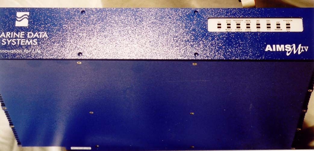
Sales & Service: Manufacturer: FCC, ID Number: Description: Model: Serial Number: USCG Approval No.: Standard: Tideland Signal Corp. Houston, TX Phone: +1 (713) 681 6101 e-mail: [email protected] 580 Kyalami Boulevard Kyalami Business Park Kyalami, Midrand, RSA xxxxxxxxxxxxxx Shipbourn automatic identification system (AIS) AIMS MIV xxxxxxxxxxxxxxxxx xxxxx ITU-R M.1371-1 IEC 60945, 61993-2 & 61162 Marine Data Systems Led Display Front Panel FCC Sticker FCC Sticker shown on front of MIV unit
Internal Photos
AIMS MIV Internal Views Date: 02-26-2003 WLI Project: 20031814 Internal Top View AIMS MIV Internal Views Date: 02-26-2003 WLI Project: 20031814 Internal Bottom View AIMS MIV Internal Views Date: 02-26-2003 WLI Project: 20031814 Panel Internal View
Internal Photos
AIMS MIV PCB Views Date: 02-26-2003 FCC ID: QXDxxxxx WLI Project: 20031814 PCB’s Views AIMS MIV PCB Views Date: 02-26-2003 FCC ID: QXDxxxxx WLI Project: 20031814 AIMS MIV PCB Views Date: 02-26-2003 FCC ID: QXDxxxxx WLI Project: 20031814 AIMS MIV PCB Views Date: 02-26-2003 FCC ID: QXDxxxxx WLI Project: 20031814 AIMS MIV PCB Views Date: 02-26-2003 FCC ID: QXDxxxxx WLI Project: 20031814 AIMS MIV PCB Views Date: 02-26-2003 FCC ID: QXDxxxxx WLI Project: 20031814 AIMS MIV PCB Views Date: 02-26-2003 FCC ID: QXDxxxxx WLI Project: 20031814 AIMS MIV PCB Views Date: 02-26-2003 FCC ID: QXDxxxxx WLI Project: 20031814 AIMS MIV PCB Views Date: 02-26-2003 FCC ID: QXDxxxxx WLI Project: 20031814 AIMS MIV PCB Views Date: 02-26-2003 FCC ID: QXDxxxxx WLI Project: 20031814 AIMS MIV PCB Views Date: 02-26-2003 FCC ID: QXDxxxxx WLI Project: 20031814
Operational Description
15-19 TROWERS WAY, REDHILL, SURREY RH1 2LH, ENGLAND TELEPHONE: +44 (0) 1737 236 313 FACSIMILE: +44 (0) 1737 768 192 Page 1 of 5 DIRECTORS: Dr. CR Jardine (Chairman) PFH Winterbach* KH Burchell* A van den Berg* *Executive www.marinedata.co.za MARINE DATA SYSTEMS (PTY)LTD. IS A SUBSIDIARY OF TRANSNET (PTY) LTD. REG. NUMBER 1993/001354/07 Co-Channel Rejection performance of the AIMS MIV This document is intended as a guide to the Co-channel rejection performance of the AIMS MIV AIS unit. The AIMS MIV unit was tested in accordance with IEC 61993-2 and passed all relevant tests except for co-channel rejection, par 15.3.4 and 15.3.5. The AIMS MIV is applying a limiter-discrimination detection demodulation method, one of the most commonly applied technologies for this purpose to date. Due to the progressive way the IEC61993-2 standard developed, it was afterwards found impossible to meet the required co-channel rejection and other RF parameters such as the inter-modulation distortion (IMD) and blocking, by applying the limiter-discriminator detection method. The trade-off in this respect was to somewhat sacrifice the co-channel rejection in order to maintain the inter-modulation distortion (IMD), blocking (also in accordance with RTCM SC117) and large signal handling requirements. It should further be understood that an IMD by default is a co-channel interferer, if not suppressed. A leading international academic and research institution has verified the above issue. The specific importance of co-channel rejection with respect to AIS is for intentional slot reuse purposes. This is only applicable when the co- channel interferer is another AIS GMSK signal. It should further be understood that co-channel rejection is a function of distance. This document shows that co-channel performance is within acceptable parameters and that the unit will not negatively influence the VHF Data Link (VDL). 15.3.4 Co-channel Rejection – 25 kHz operation The co channel test as specified in IEC 61993-2 paragraph 15.3.4, requires that the level of the wanted signal be adjusted to 3 dB above the level of the maximum usable sensitivity as specified in 15.3.1 at the receiver input terminals. This requirement is unnecessarily high and is not in accordance with other international receiver tests. If this test is performed with the wanted signal 6 dB above the level of the limit of the maximum usable sensitivity as specified in 15.3.1 the following results are obtained: Displacement -1.0 kHz -0.5kHz 0 kHz +0.5kHz +1.0 kHz Rejection -10 dB -10dB -10 dB -9dB -11 dB Table 1 - GMSK Interferer – 25kHz Note: The AIS maximum frequency error under normal condition is 0.5 kHz, therefore a maximum displacement between two AIS signals should be +/- 1 kHz and not +/- 3 kHz as required IEC 61993-2. It should further be noted that maximum displacements are extreme conditions at all times. 15-19 TROWERS WAY, REDHILL, SURREY RH1 2LH, ENGLAND TELEPHONE: +44 (0) 1737 236 313 FACSIMILE: +44 (0) 1737 768 192 Page 2 of 5 DIRECTORS: Dr. CR Jardine (Chairman) PFH Winterbach* KH Burchell* A van den Berg* *Executive www.marinedata.co.za MARINE DATA SYSTEMS (PTY)LTD. IS A SUBSIDIARY OF TRANSNET (PTY) LTD. REG. NUMBER 1993/001354/07 Co-channel - GMSK Interferer 25kHz 0 2 4 6 8 10 12 -1.0-0.50+0.5+1.0 Displacement (kHz) Rejection (-dB) GSMK 0101 (+6dB) dB Figure 1 – GMSK Interferer – 25kHz The above results indicate that the receiver performs within acceptable parameters if the wanted signal is 6 dB above the maximum usable sensitivity. Part i) of test 15.3.4 requires that a FM interferer be used instead of the previous GMSK signal (A GMSK signal is similar to another AIS unit transmitting at the same time) The FM Interferer is an illegal and abnormal operation at all times. As the RF environment is regulated and controlled, this type of operation will generally never occur. Therefore this test has very little, if any, significance in real operational terms. The results are however shown below: - WE MAY WANT TO REMOVE ALL IN YELLOW Displacement -3.0kHz 0kHz +3.0kHz Rejection -13dB -13dB -11dB Table 2 - FM Interferer – 25kHz 15-19 TROWERS WAY, REDHILL, SURREY RH1 2LH, ENGLAND TELEPHONE: +44 (0) 1737 236 313 FACSIMILE: +44 (0) 1737 768 192 Page 3 of 5 DIRECTORS: Dr. CR Jardine (Chairman) PFH Winterbach* KH Burchell* A van den Berg* *Executive www.marinedata.co.za MARINE DATA SYSTEMS (PTY)LTD. IS A SUBSIDIARY OF TRANSNET (PTY) LTD. REG. NUMBER 1993/001354/07 Co-channel - FM Interferer 25kHz 10 10.5 11 11.5 12 12.5 13 13.5 -3.0-1.5-1.0-0.50+0.5+1.0+1.5+3.0 Displacement (kHz) Rejection (-dB) FM (+6dB) dB Figure 2 – FM Interferer – 25kHz The above results indicate that the receiver performs within acceptable parameters if the wanted signal is 6 dB above the maximum usable sensitivity. 15.3.5 Co-channel Rejection – 12.5 kHz operation The results of test 15.3.5 with a wanted signal that is 6 dB above the level of the limit of the maximum usable sensitivity as specified in 15.3.1 is shown below: Displacement -1.0kHz -0.5kHz 0kHz +0.5kHz +1.0kHz Rejection -12dB -12dB -13dB -13dB -15dB Table 3 - GMSK Interferer – 12.5kHz Note: The AIS maximum frequency error under normal condition is 0.5 kHz, therefore a maximum displacement between two AIS signals should be +/- 1 kHz and not +/- 1.5 kHz as required IEC 61993-2. It should further be noted that maximum displacements are extreme conditions at all times. 15-19 TROWERS WAY, REDHILL, SURREY RH1 2LH, ENGLAND TELEPHONE: +44 (0) 1737 236 313 FACSIMILE: +44 (0) 1737 768 192 Page 4 of 5 DIRECTORS: Dr. CR Jardine (Chairman) PFH Winterbach* KH Burchell* A van den Berg* *Executive www.marinedata.co.za MARINE DATA SYSTEMS (PTY)LTD. IS A SUBSIDIARY OF TRANSNET (PTY) LTD. REG. NUMBER 1993/001354/07 Co-channel - GMSK Interferer 12.5kHz 0 2 4 6 8 10 12 14 16 -1.0-0.50+0.5+1.0 Displacement (kHz) Rejection (-dB) GSMK 0101 (+6dB) dB Figure 3 – GMSK Interferer – 12.5kHz The above results indicate that the receiver performs within a…
Text truncated - open the document above for the full version.
Operational Description
AIS 1 1. INTRODUCTION 1.1. Automatic Identification System (AIS) Overview AIS is a radio data system where two or more stations operate on one or more radio channels using Time Division Multiple Access (TDMA). These units can be mobile, base or repeater stations. Mobile stations are installed onboard vessels and integrated to the vessel’s sensors and display systems. Base stations, on the other hand, are installed on the shore side and allow remote monitoring of vessel traffic within the VHF coverage area of the base station. Base stations can be interconnected via an AIS Network to cover a larger area. Repeater stations can be used to extend the required coverage area, preferably where the traffic load is low and there is a lack of suitable communications infrastructure. The main objective of the system is to assist in safer navigation; that is, sharing ship-to-ship, positional information, speed over ground, course over ground, heading, rate of turn, static and voyage information, as well as safety-related messages. The Automatic Identification System (AIS Class A) is defined by the IMO and has been made a carriage requirement by the latest revision of SOLAS Chapter V. This does not only require the AIS to be installed, but also to provide information used for ship navigation. The AIS has been standardised by the ITU and IEC and is subject to type approval. In order to fulfil the reliability requirements of information exchange, care must be taken to ensure the AIS unit is correctly installed. The AIS Unit operates in the VHF Maritime Mobile Band and, according to its programmed mode, operates: • Ship to ship, • Ship to shore, • Shore to ship. The AIS Unit operates autonomously with minimum user intervention and has a built-in display that monitors system health and activity. It is made up of a set of easily removable modules that can be replaced without any system adjustment or calibration. It also incorporates those features of Digital Selective Calling (DSC) required by the AIS specifications. This means that the AIS Unit transmits and receives specified AIS related DSC messages on the maritime VHF DSC channel 70. 1.2. AIMS MIV Overview PI PI Motherboard AIS RCM1RFM AIS RCM2 DSC RCM Spare RCM TCMPA SMI 350 kbit/s SIB 88 kbit/s 156 to 163 Mhz 156 to 163 Mhz MCMSCM TDMA Time Bases (To RCMs, TCM) Switch Mode PSM Internal Supplies Connector Panel 24 V d.c.24 V d.c. ANT NAV Module GPS ANT 11.25 Mhz (All Modules) DBR ANT Figure 1: MIV Block Schematic Each AIMS MIV consists of: • two AIS radio receivers (AIS RCM1 and AIS RCM2), • one Digital Selective Calling (DSC) radio receiver (DSC RCM), • a Radio Frequency Module (RFM), • a Transmit Channel Module (TCM) (PA + Modulator), • a Power Supply Module (PSM), • a Main Controller Module (MCM), • a Serial Communications Module (SCM), • a Navigation Module (NAV), • a Motherboard Module, • a Connector Panel Module, • a BIT Display module. The MIV AIS is a fully synthesised AIS transponder operating in the Maritime Mobile Band. It has been designed in compliance with the listed relevant specifications against which it will be type approved. On boot up, the system receivers and transmitter are set up for the default AIS and DSC frequencies. All VDL access is in accordance with IEC 61993-2 and ITU R.M. 1371-1. Each unit is capable of transmitting and receiving messages on the radio channels. The system uses a Self-Organising Time Division Multiple Access (SOTDMA) schema to operate the radio channel. The TDMA synchronisation is controlled within the system. Application AIS 3 modules within the system determine the required update rate as well as the radio channel management. A Real-Time Operating System (RTOS) underlies the above functionality. Displaying of incoming DSC/AIS messages requires the connection of an external terminal to the PI, Keyboard Display Unit (KDU) or Pilot port. The Serial Communications Module (SCM) provides the system electrical connectivity to the ‘outside’ world via the connector panel. The MCM forms the main controlling entity of the unit. The channel processors are also interfaced to the MCM over a Serial Interface Bus (SIB). The MCM and SCM are connected via the Serial controller to Main controller Interface (SMI). The PI 1 interfaces allow connection to navigation equipment, for example, a tracking radar for positional information as well as connection to a Man Machine Interface (MMI) for the transfer of safety related messages, and navigation sensors. 1 The PI is all the external ports except the Service port. 2. INTERFACES 2.1. Internal Interface • SIB – Serial Internal Bus. Single master, multi-drop serial bus. • SMI – Serial controller to Main controller Interface. • MCM Debug interface • SCM Debug interface • Internal GPS control interface • Internal GPS data interface • Internal DBR control interface • Internal DBR data interface • External DBR interface • NMEA Sensor input interface 1/ External GPS interface • NMEA Sensor input interface 2 • NMEA Sensor input interface 3 • PI – Presentation Interface • KDU – Keyboard Display Unit interface • Pilot Interface • LR – Long Range Communications interface • Alarm relay output interface PI PI Motherboard AIS RCM1RFM AIS RCM2 DSC RCM Spare RCM TCMPA SMI 350 kbit/s SIB 88 kbit/s 156 to 163 Mhz 156 to 163 Mhz MCMSCM TDMA Time Bases (To RCMs, TCM) Switch Mode PSM Internal Supplies Connector Panel 24 V d.c.24 V d.c. ANT NAV Module GPS ANT 11.25 Mhz (All Modules) DBR ANT Figure 2: MIV Block Schematic
Test Report
WAYNE LANGSTON, INC. Model: AIMS MIV FCC ID: QXDMIV30 Date: 02-26-2003 Number of Pages: 5 WLI Project: 20031814 FCC CERTIFICATION TEST/MEASUREMENT REPORT Product Name: AIMS MIV Model: AIMS MIV Applicant/Manufacturer: Marine Data Systems 580 Kyalami Boulevard Kyalami Business Park Kyalami, Midrand, RSA By Request of: Marine Data Systems Testing Laboratory: BSH, Germany Telefication, The Netherlands Submitted By: Wayne Langston, Inc. P.O. Box 1377, League City, Texas 77574-1377 Tel: 281-337-6785; Fax: 281-337-7217; email: [email protected] Test Results: I certify that I am the person responsible for obtaining the technical information contained within this application, and that it is complete and accurate to the best of my knowledge. Tested By: Date: 02-26-2003 Wayne P. Langston Wayne Langston Incorporated authorizes the above-named Applicant company to reproduce this Report provided it is reproduced in its entirety. THIS REPORT MUST NOT BE USED TO CLAIM PRODUCT ENDORSEMENT BY ANY AGENCY OF THE U.S. GOVERNMENT WAYNE LANGSTON, INC. Model: AIMS MIV FCC ID: QXDMIV30 Date: 02-26-2003 Page i of 5 WLI Project: 20031814 TABLE OF CONTENTS 1. Introduction 1.1 Test Facility 1.2 Test samples 1.3 Test Results 2. Information required for Type Acceptance/Certification 2 1035 FCC Form 7310 2.1033(a) Applicant/Manufacturer 2.1033(2) Equipment identification 2.1033(3) Operations/Installation Manual 2.1033(4) Type of Emission 2.1033(5) Frequency Range 2.1033(6) Range of Operating Power Level 2.1033(7) Maximum power rating 2.1033(8) Voltages/Current applied 2.1033(9) Tune-up Procedure 2.1033(10) Circuit Diagram 2.1033(11) Equipment I/O 2.1033)14) Measurement Data 2.1046 Measurements required: RF Power Output 2.1047 Modulation Characteristics 2.1049 Occupied Bandwidth 2.1051 Spurious emissions at antenna terminals 2.1053 Field Strength of Spurious Radiation 2.1055 Frequency Stability Measurement Uncertainty is contained in the BSH and Telefication reports WAYNE LANGSTON, INC. Model: AIMS MIV FCC ID: QXDMIV30 Date: 02-26-2003 Page 1 of 5 WLI Project: 20031814 1. INTRODUCTION The following is a descriptive report on the Automatic Identification System manufactured by Marine Data Systems in South Africa and distributed by Tideland Signal Corporation in the U.S. The unit is a standalone transmitter / receiver combination. This unit does not provide voice communication capability. Because of the AIS only functionality the IEC/EN reports are the only test reports submitted per the DA 02-1499 document. The test reports are generated by BSH of Germany and Telefication of the Netherlands. BSH and Telefication are recognized by the US Coast Guard as capable of performing these tests. Tideland Signal Corporation, Marine Data Systems and Wayne Langston Inc. have had numerous communications with Mr. Joe Hersey of the Coast Guard and Mr. Tim Mcguire of the FCC. Information required under Part 2 and Part 80 is contained in the two reports generated by BSH and Telefication. An effort has been made to correlate the International documents to the FCC documents. This is contained in the index. These reports, BSH and Telefication, have been submitted and are in the approval process by the US Coast Guard. The test reports supporting compliance to FCC Notice(s) DA 02-1499 and DA 02-1362 are attached to this application. These test reports are based around the specifications EN 60945 and EN 61993-2 respectfully. Copies of the standards that were used for testing are included with this application.. The product has been tested and found in compliance with the United States Coast Guard requirements. The U.S. Coast Guard letter and registration is in process. WAYNE LANGSTON, INC. Model: AIMS MIV FCC ID: QXDMIV30 Date: 02-26-2003 Page 2 of 5 WLI Project: 20031814 1.1 Test Facility: Noted and Complies. This test site is located adjacent to the building in League City, Texas, 77573. All equipment is calibrated and the calibration period is 1 year. Wayne Langston, Inc. has received NVLAP Accreditation, Certificate No. 200021-0. 1.2 Test Samples: A representative sample of the Equipment Under Test (EUT), was tested by the BSH of Germany and Telefication of the Netherlands. A sample was photographed at the League City facility by Wayne Langston Inc. 1.3 Test Results: The results from this testing apply only to the sample that was tested. The findings do not make any suggestions about how the product is to be used nor does Wayne Langston, Incorporated make any recommendations regarding the product's usage. 2. INFORMATION REQUIRED FOR TYPE ACDEPTANCE PER PART 2 Paragraphs 2.1033(a) A completed FCC Form 731 is included with this application. 2.1033(1) Applicant and Manufacturer: Marine Data Systems 580 Kyalami Boulevard Kyalami Business Park Kyalami, Midrand, RSA WAYNE LANGSTON, INC. Model: AIMS MIV FCC ID: QXDMIV30 Date: 02-26-2003 Page 3 of 5 WLI Project: 20031814 US Sales & Service: Tideland signal Corporation Houston, Texas 2.1033(2) This equipment is identified as: Shipboum Automatic Identification System (AIS) 2.1033(3) Installation manual is provided with the application. 2.1033(4) The circuit/schematic functions are provided with the application. 2.1033(5) The frequency range of the AIS is 156MHZ –162.025MHZ. Normal operations on channel 70, 87B and 88B. Authority (Coast Guard) selectable to any VHF Frequency 2.1033(6) The output power level per 80.215.e.1 is +44 dbm and the actual is 41dbm Note 6 exempts 1 watt requirement. (not user selectable). 2.1033(7)) The maximum rated power of + 41. is below the maximum …
Text truncated - open the document above for the full version.
Contact Information
Applicant
Andre Van Den Berg(Technical Executive)
Technical Contact
Wayne Langston, Inc.Wayne Langston
[email protected]281-337-6785
P.O. Box 1377 · League City, Texas · United States
Test Firm
Wayne Langston, Inc.Wayne Langston
Technical Specifications
| # | Rule Parts | Frequency Range | Power Output | Emission | Tolerance |
|---|---|---|---|---|---|
| 3 | 8 | 156.525 MHz - 156.525 MHz | 12.5 W | 14K2G2B | 150 Hz |