QXS-TX030301Glucose Monitor Transmitter
Abbott Diabetes Care
Click to zoom
Application Details
- Equipment Class
- DSC - Part 15 Security/Remote Control Transmitter
- Date of Grant
- Mar 27, 2003
- Application Purpose
- Original Equipment
- Date of Application
- Mar 27, 2003
- Equipment Note
- Glucose Monitor Transmitter
- Frequency Range
- 315.02000000 - 315.02000000
- Company
- Abbott Diabetes Care
- Country
- United States
Documents & Files
Document Text
Text extracted from the exhibit documents filed with the FCC. Open a document above to read the original.
Users Manual
TheraSense Continuous Glucose Monitoring System July 8, 2002 Table of Contentsi Preface . . . . . . . . . . . . . . . . . . . . . . . . . . . . . . . . . . . . . . . . . . . . . . . . . . . . . . . . . . . . . . . . . .iii Safety and Precautions . . . . . . . . . . . . . . . . . . . . . . . . . . . . . . . . . . . . . . . . . . . . . . . . . . . . . . . . . . . . iv Important Information About Your Continuous Glucose Monitor . . . . . . . . . . . . . . . . . . . . . . iv Important Health Related Information . . . . . . . . . . . . . . . . . . . . . . . . . . . . . . . . . . . . . . . . . . . iv Help is Available . . . . . . . . . . . . . . . . . . . . . . . . . . . . . . . . . . . . . . . . . . . . . . . . . . . . . . . . . . . . . . . . iv Learning the System . . . . . . . . . . . . . . . . . . . . . . . . . . . . . . . . . . . . . . . . . . . . . . . . . . . . . . . 1 Introduction . . . . . . . . . . . . . . . . . . . . . . . . . . . . . . . . . . . . . . . . . . . . . . . . . . . . . . . . . . . . . . . . . . . . . 1 The Complete System . . . . . . . . . . . . . . . . . . . . . . . . . . . . . . . . . . . . . . . . . . . . . . . . . . . . . . . . . . . . . 1 Receiver . . . . . . . . . . . . . . . . . . . . . . . . . . . . . . . . . . . . . . . . . . . . . . . . . . . . . . . . . . . . . . . . . . . . 1 Transmitter . . . . . . . . . . . . . . . . . . . . . . . . . . . . . . . . . . . . . . . . . . . . . . . . . . . . . . . . . . . . . . . . . 2 Sensor Support Mount and Inserter . . . . . . . . . . . . . . . . . . . . . . . . . . . . . . . . . . . . . . . . . . . . . . . 2 FreeStyle Test Strip . . . . . . . . . . . . . . . . . . . . . . . . . . . . . . . . . . . . . . . . . . . . . . . . . . . . . . . . . . 3 Lancing Device . . . . . . . . . . . . . . . . . . . . . . . . . . . . . . . . . . . . . . . . . . . . . . . . . . . . . . . . . . . . . . 4 The Receiver/Transmitter Connection . . . . . . . . . . . . . . . . . . . . . . . . . . . . . . . . . . . . . . . . . . . . . . . . . 4 Using the System . . . . . . . . . . . . . . . . . . . . . . . . . . . . . . . . . . . . . . . . . . . . . . . . . . . . . . . . . . 5 Operating the Receiver . . . . . . . . . . . . . . . . . . . . . . . . . . . . . . . . . . . . . . . . . . . . . . . . . . . . . . . . . . . . 5 Selecting a Menu Option . . . . . . . . . . . . . . . . . . . . . . . . . . . . . . . . . . . . . . . . . . . . . . . . . . . . . . . 5 Replacing the Sensor . . . . . . . . . . . . . . . . . . . . . . . . . . . . . . . . . . . . . . . . . . . . . . . . . . . . . . . . . . . . . . 6 Removing the Old Sensor . . . . . . . . . . . . . . . . . . . . . . . . . . . . . . . . . . . . . . . . . . . . . . . . . . . . . . 6 Inserting a New Sensor . . . . . . . . . . . . . . . . . . . . . . . . . . . . . . . . . . . . . . . . . . . . . . . . . . . . . . . . 7 Testing Your Blood Glucose . . . . . . . . . . . . . . . . . . . . . . . . . . . . . . . . . . . . . . . . . . . . . . . . . . . . . . . 10 When to Perform a Blood Glucose Test . . . . . . . . . . . . . . . . . . . . . . . . . . . . . . . . . . . . . . . . . . 10 Using the Lancing Device . . . . . . . . . . . . . . . . . . . . . . . . . . . . . . . . . . . . . . . . . . . . . . . . . . . . . 13 Checking the System . . . . . . . . . . . . . . . . . . . . . . . . . . . . . . . . . . . . . . . . . . . . . . . . . . . . . . . . . . . . . 15 When to Perform a Control Solution Test . . . . . . . . . . . . . . . . . . . . . . . . . . . . . . . . . . . . . . . . . 15 Important Information about the Control Solution . . . . . . . . . . . . . . . . . . . . . . . . . . . . . . . . . . 15 How to Perform a Control Solution Test . . . . . . . . . . . . . . . . . . . . . . . . . . . . . . . . . . . . . . . . . 15 Control Solution Results . . . . . . . . . . . . . . . . . . . . . . . . . . . . . . . . . . . . . . . . . . . . . . . . . . . . . . 17 Troubleshooting . . . . . . . . . . . . . . . . . . . . . . . . . . . . . . . . . . . . . . . . . . . . . . . . . . . . . . . . . . 19 Error Codes . . . . . . . . . . . . . . . . . . . . . . . . . . . . . . . . . . . . . . . . . . . . . . . . . . . . . . . . . . . . . . . . . . . . 19 Error Messages . . . . . . . . . . . . . . . . . . . . . . . . . . . . . . . . . . . . . . . . . . . . . . . . . . . . . . . . . . . . . . . . . 19 Problems . . . . . . . . . . . . . . . . . . . . . . . . . . . . . . . . . . . . . . . . . . . . . . . . . . . . . . . . . . . . . . . . . . . . . . 21 Table of Contents iiTheraSense Continuous Glucose Monitor User’s Guide iii Preface The TheraSense Continuous Glucose Monitor is intended for use... I still do not have an intended use statement. It should not be used for the diagnosis of diabetes? The TheraSense Continuous Glucose Monitor helps people with diabetes monitor their sugar (glucose) level. The system provides glucose values on a continual basis allowing you to see patterns in your glucose levels. The Continuous Glucose Monitor System includes: •a sensor, which is inserted under your skin and takes glucose measurements for up to 72 hours •a wireless transmitter that connects to the sensor and sends glucose results to a receiver •a wireless receiver that captures and displays the glucose measurements sent by the transmitter Glucose levels are measured and displayed every 3 minutes from a tiny sensor inserted just below the surface of your skin. The top of the sensor sits above the skin and connects to a transmitter, which sends glucose readings to a receiver that you keep with you like a pager. The receiver displays the glucose values, and also functions as a FreeStyle blood glucose meter, allowing you to perform discrete blood glucose tests using a FreeStyle Test Strip. By getting more frequent glucose results over time, you can monitor your glucose levels more closely and gain more control of your diabetes. Understanding the continuous trend of glucose levels, rather than several isolated readings will help you and your healthca…
Text truncated - open the document above for the full version.
Cover Letter(s)
tel: 650-726-1263 fax: 650-726-1252 [email protected] Thomas N. Cokenias EMC &Radio Approvals Test & Consulting Services for Commercial, Military, International Compliance P.O. Box 1086 El Granada, CA 94018 email: [email protected] 20 March 2003 FCC Laboratory 7435 Oakland Mills Road Columbia, MD 21046 Attention: Application Examiner Reviewing Engineer Re: Request for confidentiality per Section 0.459 of FCC Rules Applicant: Therasense Inc. FCC ID: QXS-TX030301 To whom it may concern, Request is hereby submitted, on behalf of my client, Therasense Inc. to withhold from public review certain portions of the application for equipment certification for the referenced FCC identifier. In particular, the following sections of the application and report are requested to be kept confidential: Schematics Block Diagram Theory of Operations Rationale for request for confidentiality: Therasense Inc. has invested considerable time and materials in research and development to produce the referenced product. Disclosure of the confidential portions of this application to competitors would give them competitive advantage in developing similar products. If you have questions or need further information, please contact the undersigned. Sincerely, tel: 650-726-1263 fax: 650-726-1252 [email protected] THOMAS N. COKENIAS EMC Consultant/Agent for Therasense Inc.
Cover Letter(s)
From: Tom Cokenias [[email protected]] Sent: Wednesday, March 26, 2003 2:29 PM To: Mike Kuo Subject: Re: FW: Therasense Inc., FCC ID:QXS-TX030301, AN03T2721 Hi Mike, ANS1 Attached is the user manual, pdf format. I opened it no problem. If you have problem please let me know. ANS2 The loop is a small "sniffer" loop placed on top of the transmitter. The amplitude information is not calibrated but the frequency response is the same over the entire emission, and since we only require relative (-20 dBc) measurements for bandwidth, the method is valid, and has been used regularly for many years on other 15.231 applications. Test was done after radiated emissions test was performed, and it was realized occ bw data had not been taken. ANS 3 Attached are test set-up pix, a word document If you have questions or need further info, I'm in the office for the rest of the day. best regards Tom office 650 726 1263 >-----Original Message----- >From: CERTADM >Sent: Tuesday, March 25, 2003 3:28 PM >To: '[email protected]' >Subject: Therasense Inc., FCC ID:QXS-TX030301, AN03T2721 > > >Notice_content > ------------- >Question #1: User manual can not be opened. Please provide another copy of >user manual. > >Question #2: Page 5 of user manual indicates loop antenna was used for >measuring occupied BW. Please explain why loop antenna was used. > >Question #3: Please provide test setup photo. > >Best Regards > >Mike Kuo >The items indicated above must be submitted before processing can continue >on the above referenced application. Failure to provide the requested >information within 60 days of the original e-mail date may result in >application dismissal and forfeiture of the filing fee. Also, please note >that partial responses increase processing time and should not be submitted. >Any questions about the content of this correspondence should be directed to >the e-mail address listed below the name of the sender.
Cover Letter(s)
tel: 650-726-1263 fax: 650-726-1252 [email protected] Thomas N. Cokenias EMC &Radio Approvals Test & Consulting Services for Commercial, Military, International Compliance P.O. Box 1086 El Granada, CA 94018 email: [email protected] 20 March 2003 Applicant: Therasense Inc. FCC ID: QXS-TX030301 The draft manual for the referenced product will be modified to include the following statement: FCC regulations state that changes or modifications not expressly approved by Therasense could void the user's authority to operate the equipment. The applicant has been informed of this requirement . Sincerely, THOMAS N. COKENIAS EMC Consultant/Agent for Therasense Inc.
External Photos
FCC ID: QXS-TX030301page 5of 5 FCC ID: QXS-TX030301page 1of 5 Therasense Glucose Monitor TX FCC ID: QXS-TX030301 Product Photographs
ID Label/Location Info
FCC ID: QXS-TX030301 page 1of 1 Therasense Glucose Monitor TX FCC ID: QXS-TX030301 FCC ID label and location FCC ID: QXS-TX030301 Because of the limited area available on the EUT, the following statement will appear in the user manual for this product: This device complies with Part 15 of the FCC Rules. Operation is subject to the following two conditions: (1) This device may not cause harmful interference, and (2) This device must accept any interference received, including interference than may cause undesired operation
Internal Photos
FCC ID: QXS-TX030301page 2of 5 FCC ID: QXS-TX030301page 3of 5 FCC ID: QXS-TX030301page 4of 5
Test Report
Therasense M-TX HRS Blood Glucose Monitor Transmitter FCC ID: QXS-TX030301 page1 of 11 Test Report for Unlicensed Low Power Transmitter Description of device: Glucose Monitor Transmitter Unit Applicable Rule Parts: 15.205, 15.209, 15.231 Applicant: Therasense Inc. 1360 South Loop Road Alameda, CA 94502 Model No.: M-TX HRS FCC ID: QXS-TX030301 TEST REQUIREMENTS The referenced device is subject to certification under Part 2 of FCC Rules. The specific emissions limits and test requirements are found in Part 15 of FCC Rules. In addition to the device specific requirements listed in 15.231 (re-printed below), the following Part 15 requirements are universal to all unlicensed transmitters and would also apply: 15.19 Labeling requirements The FCC ID label will be placed on the product as shown in the photograph that accompanies the FCC certification application (separate attachment). 15.20 Accessories A separate receiver is associated with this product. The receiver meets all applicable requirements under Part 15. A separate verification report for the receiver has been forwarded to the manufacturer. 15.21 Information to user The users manual or instruction manual for an intentional or unintentional radiator shall caution the user that changes or modifications not expressly approved by the party responsible for compliance could void the user's authority to operate the equipment. Such a statement will be included in the user manual for the referenced equipment and in the user manual for its companion receiver. 15.31 Measurement standards American National Standards Institute (ANSI) C63.4-1992, entitled "Methods of Measurement of Radio- Noise Emissions from Low-Voltage Electrical and Electronic Equipment in the Range of 9 kHz to 40 GHz,", was followed in performing all transmitter and receiver tests. 15.32 Frequency range of radiated emissions measurements Measurements were made from the lowest frequency generated by the device up to 3.15 GHz, the 10 th harmonic of the fundamental emission Therasense M-TX HRS Blood Glucose Monitor Transmitter FCC ID: QXS-TX030301 page2 of 11 15.35 Measurement detector functions and bandwidths As specified in ANSI C63.4 for the various tests required. When average radiated emission measurements are specified in this part, including emission measurements below 1000 MHz, there also is a limit on the radio frequency emissions, as measured using instrumentation with a peak detector function, corresponding to 20 dB above the maximum permitted average limit for the frequency being investigated. Where average reading measurements are specified, and pulsed operation is employed, the measurement field strength shall be determined by averaging over one complete pulse train, including blanking intervals, as long as the pulse train does not exceed 0.1 seconds. 15.109 Radiated Emissions (unintentional radiators) Radiated emissions testing was performed for the companion receiver. Emissions levels did not exceed measurement equipment noise floor (at least 15 dB below limits). 15.203 Antenna requirement The transmitter antenna is internal and permanently attached, and complies with this requirement. 15.204 External radio frequency power amplifiers and antenna modifications NOT APPLICABLE 15.205 Restricted bands of operation Several transmitter harmonic frequencies fall into restricted bands. Measurement results indicate all restricted band emissions were more than 21 dB below 15.209 limits. 15.206 Conducted Emissions NOT APPLICABLE. Transmitter is battery operated only. Emissions limits and test data are found below. The Therasense transmitter model M-TX HRS meets all relevant requirements. THOMAS N. COKENIAS 24 February 2003 EMC and Radio Regulatory Consultant Agent for Therasense Inc. Therasense M-TX HRS Blood Glucose Monitor Transmitter FCC ID: QXS-TX030301 page3 of 11 15.205 Restricted bands of operation. Only spurious emissions are permitted in any of the frequency bands listed below: The field strength of emissions appearing within these frequency bands shall not exceed the limits shown in Section 15.209. MHz MHz MHz GHz 0.090 - 0.110 10.495 - 0.505 2.1735 - 2.1905 4.125 - 4.128 4.17725 - 4.17775 4.20725 - 4.20775 6.215 - 6.218 6.26775 - 6.26825 6.31175 - 6.31225 8.291 - 8.294 8.362 - 8.366 8.37625 - 8.38675 8.41425 - 8.41475 12.29 - 12.293 12.51975 - 12.52025 12.57675 - 12.57725 13.36 - 13.41 16.42 - 16.423 16.69475 - 16.69525 16.80425 - 16.80475 25.5 - 25.67 37.5 - 38.25 73 - 74.6 74.8 - 75.2 108 - 121.94 123 - 138 149.9 - 150.05 156.52475 - 156.52525 156.7 - 156.9 162.0125 - 167.17 167.72 - 173.2 240 - 285 322 - 335.4 399.9 - 410 608 - 614 960 - 1240 1300 - 1427 1435 - 1626.5 1645.5 - 1646.5 1660 - 1710 1718.8 - 1722.2 2200 - 2300 2310 - 2390 2483.5 - 2500 2655 - 2900 3260 - 3267 3332 - 3339 3345.8 - 3358 3600 - 4400 4.5 - 5.15 5.35 - 5.46 7.25 - 7.75 8.025 - 8.5 9.0 - 9.2 9.3 - 9.5 10.6 - 12.7 13.25 - 13.4 14.47 - 14.5 15.35 - 16.2 17.7 - 21.4 22.01 - 23.12 23.6 - 24.0 31.2 - 31.8 36.43 - 36.5 15.109 Radiated emission limits, general requirements. Except as provided elsewhere in this paragraph the emissions from an intentional radiator shall not exceed the field strength levels specified in the following table: Frequency (MHz) Field Strength uV/m Measurement distance, m 0.009 - 0.490 0.490 - 1.705 1.705 - 30.0 30 - 88 88 - 216 216 - 960 Above 960 2400/F(kHz) 24000/F( 30 100 ** 150 ** 200 ** 500 300 30 30 3 3 3 3 ** Except as provided in paragraph (g), fundamental emissions from intentional radiators operating under this Section shall not be located in the frequency bands 54-72 MHz, 76-88 MHz, 174-216 MHz or 470-806 MHz. Therasense M-TX HRS Blood Glucose Monitor Transmitter FCC ID: QXS-TX030301 page4 of 11 Section 15.231 Periodic operation in the band 40.66 - 40.70 MHz and above 70 MHz. (c) The bandwidth of the emission shall be no wider than 0.25% of the center frequency for devices operating above 70 MHz and below 900 MHz. For devices operating above 900 MHz, the emis…
Text truncated - open the document above for the full version.
Test Setup Photos
Therasense TX Test Set-up Photos FCC ID: QXS-TX030301 Radiated emissions test set-up Transmitter in X – axis TX Y- axis and Z – axis orientation (TX shown in Y axis)
Contact Information
Applicant
Jody J Savage(Regulatory Affairs)
Test Firm
Compliance Certification Services IncSteve Cheng
Technical Specifications
| # | Rule Parts | Frequency Range | Power Output |
|---|---|---|---|
| 1 | 15.231(e) | 315.02 MHz - 315.02 MHz | - |
Other Applications from Abbott Diabetes Care
QXS-LIBDC1
Mar 24, 2026Libre Duo
Equipment Class
DTS - Digital Transmission System
QXS-LIB02
Apr 28, 2021Glucose Monitoring Reader
Equipment Class
DXX - Part 15 Low Power Communication Device Transmitter
QXS-LIB02S
Apr 26, 2021Glucose Monitoring Sensor
Equipment Class
DTS - Digital Transmission System
QXS-LIB01
Oct 14, 2014Freestyle Libre Glucose Monitoring System
Equipment Class
DXX - Part 15 Low Power Communication Device Transmitter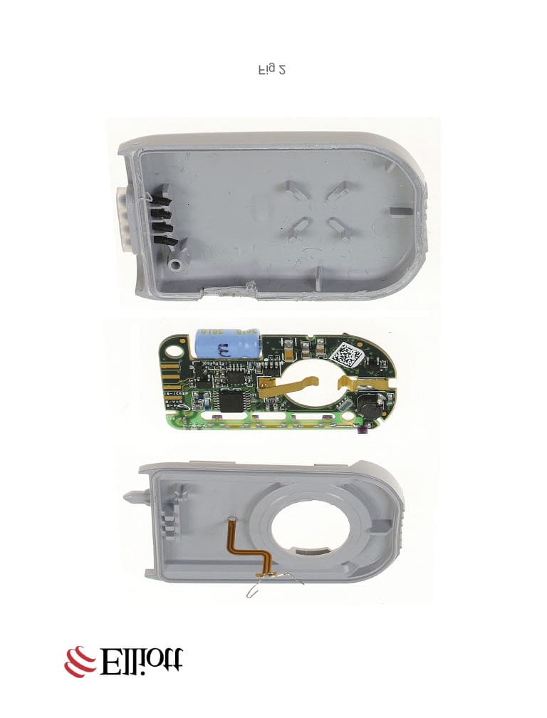
QXSTX111004
Jan 17, 2005Diabetes Monitor Transmitter
Equipment Class
DSC - Part 15 Security/Remote Control Transmitter