QYQ830-100-146V01Wireless Sash Sensor system
Phoenix Controls Corporation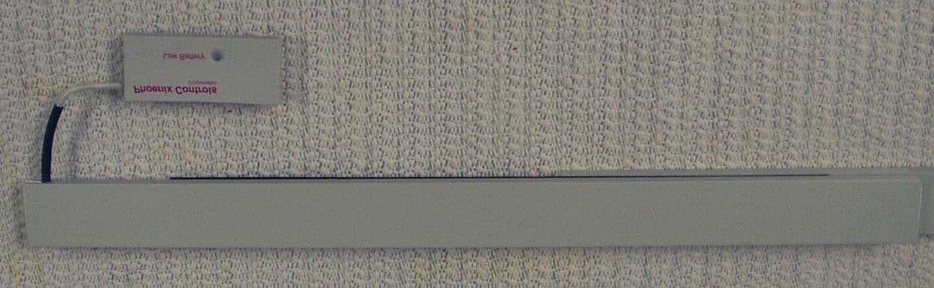
Click to zoom
Application Details
- Equipment Class
- DSC - Part 15 Security/Remote Control Transmitter
- Date of Grant
- Jul 10, 2003
- Application Purpose
- Original Equipment
- Date of Application
- May 11, 2003
- Equipment Note
- Wireless Sash Sensor system
- Frequency Range
- 433.80000000 - 434.00000000
- Company
- Phoenix Controls Corporation
- Country
- United States
Documents & Files
Document Text
Text extracted from the exhibit documents filed with the FCC. Open a document above to read the original.
Users Manual
WIRELESS SASH SENSOR 75 Discovery Way•Acton, Massachusetts 02458•Telephone (978) 795-1285•Fax (978) 795-1111 ©2003 Phoenix Controls Corporation. Specifications subject to change without notice. Rev. 5/03WIRELESS SASH SENSOR—1 OF 7 The Phoenix Controls Wireless Sash Sensor system detects a fume hood’s sash position through a radio signal that is transmit- ted to a wireless receiver. Sensors can be configured to operate with the sash configurations found on most VAV fume hoods. These sash sensors help maintain a constant average face velocity at the sash opening. SPECIFICATIONS Wireless Sash Sensor connected to horizontal magnet bar. Construction Tr a n s m i t t e r : • Fabricated in a corrosive resistent plastic enclosure capable of withstanding harsh fumes produced in a typical fume hood • Resistant to all chemicals that the cur- rent sash sensors are resistant to (which chemicals are the other sash sensors resistant to?) • Color: light gray Receiver: • Housed in a corrosive resistant plastic enclosure • Color: black Power Supply 3-volt Lithium coin cell battery; nominal capacity 70 mA-hours at a nominal load of 15K ohms. Operating Range Provides dual voltage input capability. The supply can operate from 24 VAC or 15 VDC input. • 24 VAC input: 18-30 VAC • 15 VDC input: 14.5-18 VDC Transmitter Frequency 433 MHz Dimensions • Transmitter: 2” W x 0.95” H x 0.25” D • Receiver: 5.895” W x 3.114” H x 1.805” D • Magnet bar: 1” W x 0.3” D. Bar lengths made to order; maximum length available is 75” cumulative TABLE OF CONTENTS Features, Applications and Operation ........ 2 Ordering Guide ......................................... 2 Mounting and Installation ......................... 3 Field Adjustments ...................................... 3 Points and Wiring...................................... 4 Maintenance..............................................4 2 OF 7—WIRELESS SASH SENSOR©2003 Phoenix Controls Corporation. Specifications subject to change without notice. Rev. 5/03 The WSS uses existing sash sensing technology, replacing the two-conductor wire that runs from the horizontal sash sensor to the horizontal/vertical (H/V) card with a low-power wireless radio frequency (RF) transmitter. The transmitter detects the change in sash position and trans- mits the signal to a receiver that is located no more than 20 feet away. The WSS receiver replaces the H/V card, which will be responsible for calculating the proportional signal that is sent to the fume hood monitor. Digitizing of the sash signal is accomplished by taking the current analog signal, passing it through an A/D con- verter, encoding it, and wirelessly transmitting to a receiver. The receiver then takes the transmitted signal, decodes it, converts it to an analog voltage, and amplifies it to a 0-10 VDC signal for the hood exhaust valve or the fume hood monitor. The receiver listens to multiple transmitters. Multiple transmitters can be in the same zone transmitting to mul- tiple receivers. For example, there could be two hoods, side-by-side, in a lab with hood 1 having two sashes and hood 2 having four sashes. Hood 1 will have one trans- mitter and hood 2 will have two transmitters; both hoods will have their own receivers. When hood 1 sash opens, the transmitter encodes the data and transmits the data to hood 1's receiver. Only receiver for hood 1 will process the data, hood 2's receiver should discard the data. NOTE: Need to add drawings to this section. FEATURES, APPLICATIONS AND OPERATION ORDERING GUIDE TYPE OF HOOD SASH CONFIGURATION VSS1 - For vertical sash hoods HSS1 - For horizontal sash hoods CSS1 - For combination horizontal/vertical sash hoods SSS1 - For special sash hoods TOTAL NO. OF VERTICALLY-MOVING SASHES TOTAL NO. OF HORIZONTALLY-MOVING SASHES SENSOR/MAGNET BAR LENGTH (in whole inches; round down) Blank for vertical sash hoods Mike, I inserted this as a placeholder...wasn’t sure how much you’d need of this for the wireless version. I cop- ied this from our gen- eral sash sensor product data sheet. ©2003 Phoenix Controls Corporation. Specifications subject to change without notice. Rev. 5/03WIRELESS SASH SENSOR—3 OF 7 MOUNTING AND INSTALLATION Mounting and Orientation Transmitter The wireless transmitter shall be field mounted near the current sensor bar with a distance of no more than two inches from the actual senor bar. The transmitter shall have double sticky-back tape on one side for easy mounting. Receiver The receiver shall be field mounted somewhere above the hood or in a sensible location. The receiver mounting location shall not exceed a total distance of 20 feet from the farthest wireless transmitter. Installation Transmitter The wireless transmitter will be field mounted either underneath or above the current sash sensor bar. The sensor bar (two-conductor wire) will be field wired directly into the transmitter and the transmitter may not be more than two inches away from the sensor bar. The transmitter will also have a double sticky-back tape so that the unit may be affixed to the hood sash. Receiver The receiver will be field installed either above the hood or next to the fume hood monitor. In most cases, the receiver will be field mounted above the hood and no more than 20 feet away from the farthest transmitter. NOTE: Need to add drawings to this section. FIELD ADJUSTMENTS (CAILBRATION, CONFIGURATION, ETC.) The wireless transmitter is uniquely identified, so that the relationship between a transmitter and a receiver is one-to- one. The Phoenix factory address each wireless transmitter so that it communicates to specific receiver. The receiver is uniquely identified so the relationship between a receiver and a transmitter is one-to-many. Each receiver will be addressed via the front-end commissioning software. 4 OF 7—WIRELESS SASH SENSOR©2003 Phoenix Controls Corporation. Specifications subject to change without notice. Rev. 5/03 POINTS & WIRING The sensor bar is field wired directly to the transmitter. …
Text truncated - open the document above for the full version.
Cover Letter(s)
June 3, 2003 Attn: Diane Poole Federal Communications Commission 445 12th Street SW Washington, DC 20554 RE: CONFIDENTIALITY REQUEST FOR WIRELESS SASH SENSOR FCC ID# QYQ830-100-146V01 Ms. Poole: This letter serves as an official request for confidentiality under FCC rule Section 0.459. We have requested that the schematics diagrams and block diagrams required to be submitted with this application be withheld from public review. The documents are company proprietary information that could never get into the possession of our competition. Sincerely, Mike Desai Director of Software Engineering & IT
External Photos
c:\clients\phoenix\sash_sensor\part15\sashtx_external_pictures.doc 115 Cedar Street Milford, MA 01757 (508) 478-8964 FOR PHOENIX CONTROLS SASH TRANSMITTER PROJECT PRODUCT EXTERNAL PICTURE View of assembled unit, with 13" sensor bar, mounted to a sheet of 1/8" acrylic with double stick tape. Mounted to the back of the acrylic is a 13" bar magnet, to simulate a partially closed sliding window sash. 05/05/03 c:\clients\phoenix\sash_sensor\part15\sashtx_external_pictures.doc Page 2 Front view from below Front view from above Rear view from below Rear view from above
ID Label/Location Info
.970 2.250 1.357 .287 LED LOCATION .970 2.250 1.357 .287 LED LOCATION Print Specifications Red prints PMS 485 Artwork is silkscreened on P/N 520-220-160 File Location / Name G:\Documentation\QualityManagementSystem\ theVAULT\MARKETINGdocumentation\Manufacturing\ Wireless Sash Sensor\Wireless Sash Sensor (603-220-002).ai Description Wireless Sash Sensor Cover artwork Revision History Rev. A 20691 21-Apr-03 ECODate Material Specifications B 20790 5-May-03 INSIDE Front Cover Front Cover FCC ID: QYQ830-100-146V01 USE CR2025 BATTERY
Internal Photos
c:\clients\phoenix\sash_sensor\part15\sashtx_internal_pictures.doc 115 Cedar Street Milford, MA 01757 (508) 478-8964 FOR PHOENIX CONTROLS SASH TRANSMITTER PROJECT PRODUCT INTERNAL PICTURE Front View of Transmitter Board Back view of Transmitter Board View of Board, as installed inside plastic case.
Operational Description
c:\clients\phoenix\sash_sensor\part15\desc_of_operation1.doc 115 Cedar Street Milford, MA 01757 (508) 478-8964 MEMORANDUM To: Mike Desai From: John M. Nelson Date: 12 May 2003 Subject: How the sash transmitter module operates Description of Operation: It monitors the status of the sash opening through the use of a bar magnet and a series of magnetically actuated (reed style) switches. When the sash window is opened or closed, the position of the bar magnet relative to the reed switches changes, causing more (or less) switches to close. On detecting a change in the state of those switches, the system will automatically transmit a single message (that takes less than two seconds) containing its identity, and a code for how many switches have been activated. To ensure system integrity, it will also transmit a message indicating its status once every hour. CC: Techen:
Test Report
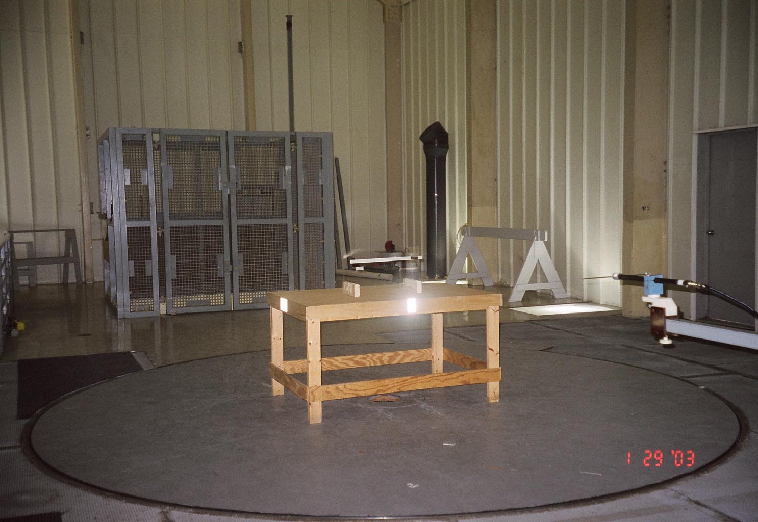
EMC001677-NE EMC000142-NE Reg. No. R-1145 Reg. No. C-1205 BSMI Lab No. SL2-IN-E-1018 Cert. No. 00-016 ELA No. 174 Reg. No. 91007 Reg. No. 91008 Test Site Services. Inc. NVLAP Lab Code 100419-0 EMI Test Report For Phoenix Controls, Inc Sash Transmitter Radiated Emissions Duty Cycle Occupied Bandwidth FCC, Part 15 Subpart C Section 15.231 a, b, c Test # B03025 Test Site Services, Inc. P.O. Box 766 Marlboro, MA 01752 U.S.A. Phone/Fax: (508) 481-1684 This report shall not be reproduced, in whole or in part without the written approval of Test Site Services Inc. This report must not be used by the recipient to claim product endorsement by NVLAP or any other agency of the U.S. Government The test results stated in this report are valid only for the specific items tested Test Site Services, Inc. Report # B03025 Tested for: Phoenix Controls 1/28-29/03 EUT: Sash Transmitter Table of Contents Administrative Data.............................................................................................................2 EUT Description..................................................................................................................3 Test Summary......................................................................................................................4 Block Diagram for...............................................................................................................5 EUT Technical Data – Block Identifier 1............................................................................6 Cable Descriptions...............................................................................................................7 Test Software Description....................................................................................................8 Operational Mode(s) During Test........................................................................................8 EUT I/O Ports – Cable Configuration.................................................................................9 Test Equipment List...........................................................................................................10 Appendix A Test Data......................................................................................................A1 Appendix B Test Photographs..........................................................................................B1 Appendix C Test Procedures.............................................................................................C1 Appendix D Measurement Facilities Information............................................................D1 Accreditation / Approval...................................................................................................D3 Test Site Services, Inc. Report # B03025 Page 1 of 10 Tested for: Phoenix Controls 1/28-29/03 EUT: Sash Transmitter EMI Test Report for Phoenix Controls Test Number : B03025 Product Name : Sash Transmitter Regulation : FCC, Part 15, Subpart C Section 15.231 a, b, c Date : 1/28-29/03, 4/29/03 Report Reviewed & Accepted by: Phoenix Controls 75 Discovery Way Acton, MA 01720 Phone:1-978-795-1285 Fax :1-978-795-1112 Report Issued By: Richard L. Wiedeman, Laboratory Director Tested By: T. Charron, Test Engineer This test report is not valid without the signatures of Test Site Services, Inc. personnel. Test Site Services, Inc. Report # B03025 Page 2 of 10 Tested for: Phoenix Controls 1/28-29/03 EUT: Sash Transmitter Administrative Data Regulation : FCC, Part 15, Subpart C Section 15.231 a, b, c; 15.205 Level : 15.231 b, 15.209, 15.35 Test Method : ANSI C63.4-1992 Test Type : Qualification EUT Classification : Intentional Radiator Modulation : on / off Manufacturer : Phoenix Controls EUT Type/Model # : Sash Transmitter / 830-100-146 Date(s) of Test : 1/28-29/03, 4/29/03 Customer Personnel : John Nelson TSS Personnel : R. Wiedeman EMC Engineer : T. Charron Test Engineer Test Location : Open Area Test Site Test Site Services, Inc. 30 Birch St. Milford, MA 01757 U.S.A. NOTICE : FCC Rule 2.955 requires that a Verification Report for a Class A Computing Device must be signed by "an Official of the Company responsible for the device". A signature block has been provided on the first page for this purpose. Test Site Services, Inc. Report # B03025 Page 3 of 10 Tested for: Phoenix Controls 1/28-29/03 EUT: Sash Transmitter EUT Description The EUT (Sash Transmitter) is a device to control the air flow of a chamber. A complete description of the EUT may be found on block identifier 1 page. The tests were run in a typical configuration including the following equipment: 1) Sash Transmitter (EUT) 2) Sensor Bar REASON FOR TEST: Qualification CHANGES MADE DURING TEST: 1) EUT Firmware was modified to continuously transmit to facilitate R.F. measurement For Radiated Emissions DEVIATIONS FROM STANDARD TEST METHOD: None Test Site Services, Inc. Report # B03025 Page 4 of 10 Tested for: Phoenix Controls 1/28-29/03 EUT: Sash Transmitter Test Summary The EUT (Sash Transmitter) complied with the FCC Part 15 Subpart C, Section 15.231 requirements for an intentional radiator when tested in the system configuration defined herein. • Radiated Emissions (15.231b, 15.209) The following table indicates the margins (i.e. difference between measurement point and limit) of the twenty one (10) worst case data points: TEST CLASS MARGIN TO SPEC (db) FREQUENCY (MHz) Radiated Emissions E Field (3.6 VDC) Fundamental Frequency -8.8 433.84 Spurious / Unwanted -7.8 1301.58 Emissions -9.7 400.03 -10.8 244.08 -12.4 2169.26 -12.6 280.00 -15.0 120.03 -16.7 3904.76 -19.1 1735.28 -20.9 4338.43 • Duty Cycle (15.231 a) 15.231, a 2 : Device operational mode, EUT transmits 4 packets in 1.26 seconds when activated. 15.231, a 3 : During Supervisory mode, rate of transmission is 3 packets in less than 1 second every 72 minutes. • Occupied Bandwidth (15.231, c) The 20 dB bandwidth of the fundamental and all sidebands is less than .25% of the c…
Text truncated - open the document above for the full version.
Contact Information
Applicant
Mike Desai(Director of Software & IT)
Technical Contact
Phoenix Controls CorporationTom Hotaling
[email protected]978-795-3415
75 Discovery Way · Acton, Massachusetts · United States
Test Firm
Test Site Services Co.Lawrence Lee
Technical Specifications
| # | Rule Parts | Frequency Range | Power Output |
|---|---|---|---|
| 1 | 15.231 | 433.8 MHz - 434 MHz | - |