QZOL2300Indoor RLF
THE DESIGNERS EDGE INC.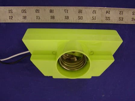
Click to zoom
Application Details
- Equipment Class
- 8CC - Part 18 Consumer Device
- Date of Grant
- May 05, 2003
- Application Purpose
- Original Equipment
- Date of Application
- May 05, 2003
- Equipment Note
- Indoor RLF
- Frequency Range
- 0.02800000 - 0.04000000
- Company
- THE DESIGNERS EDGE INC.
- Country
- United States
Documents & Files
Document Text
Text extracted from the exhibit documents filed with the FCC. Open a document above to read the original.
Users Manual
8 ENGLISH Model# L-2300 PORTABLE WORKLIGHT OPERATING INSTRUCTIONS • Fixture design may vary Mailing Address (please print): USE OF IMPROPER BULB WILL VOID YOUR WARRANTY! Prices subject to change without prior notice. Qty. Item No. Description Each (1) Each 2 or more Extended Price L-7659.998.99 1.50 65 watt, Mogul Base Fluorescent Bulb Subtotal Shipping and handling Sales Tax (Washington State Only) 8.8% TOTAL (Amount of check) The Designer’s Edge 11730 N. E. 12th Street Bellevue, WA 98005 Ph: (425) 637-9601 Fax: (425) 637-9603 www.designersedge.com 27 ENGLISH 2 Year Warranty on fixture (Does not apply to bulbs, which have no warranty) Congratulations and Thank You from The Designer’s Edge! The fixture you have purchased should give you years of trouble free service. We take pride in the design and construction of each of our products and work to maintain the quality of our materials and craftsmanship to assure your satisfaction. This product is warranted to be free of defects in workmanship and materials for a period of 2 years from the original date of purchase. If any problems appear (other than burnt out bulbs, which carry no warranty) within 2 years, the purchaser may return the item, freight prepaid, together with a copy of your original purchase receipt to: The Designer’s Edge 11730 N. E. 12th street Bellevue, Washington 98005 Upon receipt of the item prepaid with a letter describing the problem, and a check for $7.50 to cover return postage and handling, the company will at its option either repair or replace the defective part or fixture at no charge to the purchaser. This warranty does not apply to fixtures that have been used for rental or commercial purposes. It does not cover fixtures that have been altered in any way or fixtures that have been subject to misuse, accidents or damage in transit. IN NO CASE SHALL THE COMPANY BE LIABLE FOR ANY INCIDENTAL OR CONSEQUENTIAL DAMAGES. NO CHARGES WILL BE ACCEPTABLE FOR UNAUTHORIZED REPAIRS, PARTS OR SERVICE. Some states do not allow limitations on how long an implied warranty lasts and do not allow exclusions or limitation of incidental damages, so parts or all of this warranty limitations or exclusions may not apply to you. Legal warranty rights will vary from state to state and you may have other rights. IMPORTANT NOTICE: Every attempt has been made to deliver a quality product that will give you years of trouble free service. In the event that you have problems with the fixture. Please DO NOT RETURN TO PLACE OF PURCHASE. PLEASE CALL THE NUMBER BELOW FOR BULB OR PARTS PROBLEMS: (425) 637-9601 8-5 PM West Coast Time. All warranty problems are handled directly through The Designer’s Edge. www.designersedge.com Expiration date I hereby authorize the amount of___________ to be charged against my above card. Cardholder Signature (as shown on credit card) Month Year Method of Payment: All prices stated in US Dollars. Check enclosed (US funds only) Charge to my: Visa Mastercard Discover Please indicate credit card number and expiration date with charge orders. To replace our unique, fluorescent light bulb please complete the information on the reverse side and send check or money order payable to: The Designer’s Edge 11730 N.E. 12th Street Bellevue, WA 98005-2458 (425) 637-9601 FAX: (425) 637-9601 www.designersedge.com REPLACEMENT BULB ORDER CARD Safety Instructions for Fluorescent Worklights READ ALL INSTRUCTIONS - WARNING: When portable fixtures are used outdoors basic safety precautions should always be followed to reduce the risk of fire, electric shock and personal injury, including the following: A. Use only three wire outdoor extension cords that have three prong grounding plugs and grounding receptacles that accept the appliances plug. B. Ground fault circuit interrupter (GFCI) protection should be provided on the circuit(s) or outlet(s) to be used for the wet location portable fixture. C. Use only with extension cord for outdoor use, such as an extension cord type SW, SW-A, SOW, SOW-A, STW, STW-A, STOW, STOW-A, SJW, SJW-A, SJOW, SJOW-A, SJTW, SJTW-A, SJTOW, SJTOW-A. 36 ENGLISH • When replacing the bulb in this lamp always turn off and give ample time for lamp to cool. Also unplug lamp from power source. Always close face of lamp securely before turning power back on. • Never operate the lamp with missing glass safety shield. • This lamp is not intended for use nor safe to use in potentially dangerous locations such as places with explosive or flammable atmospheres. • Do not handle this lamp when standing on wet or damp surfaces or in water. To reduce the risk of electrical shock, this light should always be plugged into properly grounded outlet. Do not remove the ground wire or grounded plug from the lamp. • Always use a grounded cord with electrical capacity to properly handle this light and other tools you might be using. Never use light around swimming pool, hot tubs or saunas. • Never use around heavy volatile fluids such as gasoline. • This product may cause interference with radios, cordless phones, or devices which use a wireless remote control, such as televisions. If interference occurs move the product away from the device, plug the product into a different outlet, or move the product out of the line of sight of the remote control. Complies with part 18 of FCC. • Always handle fluorescent bulb by plastic base. Glass gets hot! • Use only L-765 65W Florescent bulb. Any other bulb may damage unit and create hazard. • This unit has a polarized plug. One blade is wider than the other. As a safety feature this plug will fit in a polarized outlet only one way. If plug does not full fit in outlet, reverse the direction. If it still does not fit, contact a qualified electrician. Never use with an extension cord unless the plug can be fully inserted. Do not attempt to defeat this safety feature. ESPANOL FCC Warning This equipment has been tested and found to comply with the limits for a Consumer device, pursuant to Part 18 of the…
Text truncated - open the document above for the full version.
External Photos
EUT – Combination View EUT – Lamp View EUT – Ballast View
ID Label/Location Info
APPENDIX A - FCC PRODUCT LABELING AND WARNING STATEMENT Proposed FCC Label Format FCC ID: QZOL2300 Specifications: Text is Black or white in color and is left justified. Labels are printed in indelible ink on permanent adhesive backing or silk-screened onto the EUT or shall be affixed at a conspicuous location on the EUT. Proposed Label Location on EUT Proposed FCC Label Location FCC Warning Statement This device complies with Part 18 of FCC rules. Information on the following matters shall be provided to the user in the instruction manual or on the packaging if an instruction manual is not provided for any type of any ISM equipment: a. The interference potential of the device or system b. Maintenance of the system c. Simple measures that can be taken by the user to correct interference. EUT: Combination View label here
Internal Photos
EUT – Component View EUT – Solder View EUT – Port View
Test Report
Note: The test report is specially limited to the use of the above client company and the product model. It may not be duplicated without prior written consent of Bay Area Compliance Laboratory Corporation. This report must not be used by the client to claim product endorsement by NVLAP or any agency of the U.S. Government FCC ID PER PART 18 MEASUREMENT AND TEST REPORT FOR THE DESIGNERS EDGE INC. 11730 N.E. 12 th Street Bellevue, WA 98005 USA FCC ID: QZOL2300 March 12, 2003 This Report Concerns: Original Report Equipment Type: Indoor RLF Test Engineer:Jerry Wang Report Number:R0302244 Test Date:March 7, 2003 Reviewed By:Hans Mellberg Prepared By:Bay Area Compliance Laboratory Corporation 230 Commercial Street Sunnyvale, CA 94085 Tel: (408) 732-9162 Fax: (408) 732-9164 THE DESIGNERS EDGE INC. FCC ID: QZOL2300 Report # R0302244RptPage 2 of 8FCC Part 18 Test Report TABLE OF CONTENTS 1 - GENERAL INFORMATION.................................................................................................................................................3 1.1 PRODUCT DESCRIPTION FOR EQUIPMENT UNDER TEST (EUT).........................................................................................3 1.2 OBJECTIVE................................................................................................................................................................................3 1.3 RELATED SUBMITTAL(S)/GRANT(S)......................................................................................................................................3 1.4 TEST METHODOLOGY.............................................................................................................................................................3 1.5 TEST FACILITY.........................................................................................................................................................................3 1.6 TEST EQUIPMENT LIST AND DETAILS...................................................................................................................................4 1.7 LOCAL SUPPORT EQUIPMENT................................................................................................................................................4 1.8 INTERFACE PORTS AND CABLING..........................................................................................................................................4 2 - SYSTEM TEST CONFIGURATION..................................................................................................................................5 2.1 JUSTIFICATION.........................................................................................................................................................................5 2.2 EUT EXERCISE PROGRAM......................................................................................................................................................5 2.3 SCHEMATICS/BLOCK DIAGRAM............................................................................................................................................5 2.4 EQUIPMENT MODIFICATIONS.................................................................................................................................................5 2.5 CONFIGURATION OF TEST SYSTEM.......................................................................................................................................6 2.6 TEST SETUP BLOCK DIAGRAM..............................................................................................................................................6 3 - CONDUCTED EMISSIONS TEST DATA........................................................................................................................7 3.1 MEASUREMENT UNCERTAINTY.............................................................................................................................................7 3.2 EUT SETUP...............................................................................................................................................................................7 3.3 EMI RECEIVER SETUP............................................................................................................................................................7 3.4 TEST PROCEDURE....................................................................................................................................................................7 3.5 SUMMARY OF TEST RESULTS.................................................................................................................................................8 3.6 CONDUCTED EMISSIONS TEST DATA....................................................................................................................................8 THE DESIGNERS EDGE INC. FCC ID: QZOL2300 Report # R0302244RptPage 3 of 8FCC Part 18 Test Report 1 - GENERAL INFORMATION 1.1 Product Description for Equipment Under Test (EUT) The THE DESIGNERS EDGE INC., Model: L2300 65W or the "EUT" as referred to in this report is an indoor light, which measures 6.5”L x 3.75”W x 3.00”H. Note: The test data collected are from a representative production sample provided by the manufacturer. 1.2 Objective This Following test report is prepared on behalf of THE DESIGNERS EDGE INC. in accordance with Part 2, Subpart J, and Part 18, Subparts A and B of the Federal Communication Commissions rules. The objective of the manufacturer is to demonstrate compliance with FCC Part 18 limit requirements for Industrial, Scientific, and Medical Equipment. 1.3 Related Submittal(s)/Grant(s) No Related Submittals. 1.4 Test Methodology All measurements contained in this report were conducted in accordance with MP-5, FCC Methods of Measurements of Radio Noise Emissions from Industrial, Scientific, and Medical Equipment. All radiated and conducted emission measurements were performed at Bay Are…
Text truncated - open the document above for the full version.
Contact Information
Applicant
Stephen L Svinth(Director of Product Development)
Test Firm
Bay Area Compliance LaboratoryJohn Chan
Technical Specifications
| # | Rule Parts | Frequency Range | Power Output |
|---|---|---|---|
| 1 | 18 | 0.028 MHz - 0.04 MHz | - |