R2R04HUSKY752 Channel FM Radio Control System
Proton Control Systems, Inc.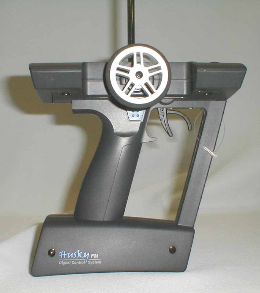
Click to zoom
Application Details
- Equipment Class
- TNB - Licensed Non-Broadcast Station Transmitter
- Date of Grant
- Oct 10, 2004
- Application Purpose
- Original Equipment
- Date of Application
- Oct 10, 2004
- Equipment Note
- 2 Channel FM Radio Control System
- Frequency Range
- 75.41000000 - 75.99000000
- Company
- Proton Control Systems, Inc.
- Country
- United States
Documents & Files
Document Text
Text extracted from the exhibit documents filed with the FCC. Open a document above to read the original.
Users Manual
HUSKY FMFM 2 Channel FM Radio Control System USER MANUAL Proton Control Systems Inc. GGGGGGGGGGGGGGGGGGGGGGGGGGGGGGGGyGYUW G G GGGGGGGzV~G}GYUW ̄GYWWZGwGjGz GpU 1. Safety Precautions Transmitter and receiver Operating Frequency Battery Maintenance 2. Features 3. Preparation & Getting Started HUSKY 2 Channel FM TRANSMITTER Adaptation for Left-hander Antenna Installation Loading the Batteries Charging Power switch Direct Servo Control USB Connection Standing Specification KEN 2 Channel FM RECEIVER Installation Frequency Setting Specification 4. Data Setting & Programming Control panel Normal display Function map Direct Access Functions Digital Trim Dual Rate Stopwatch Table of Contents System Mode Functions Model Name Trim Rate LCD Contrast Frequency Data Copy Pit Mode Functions Model Select Setting Level Servo Reverse Sub Trim Data Reset Circuit Mode Functions End Point Adjustment Response Steering Speed 2-Step Steering Speed Throttle Speed 2-Step Throttle Speed Start 3-Step ABS ABS Auto Steering Control Punch Idle Up 5. Approvals 6. Warranty & Service Appendix Frequency Chart Table of Contents (continued) Safety Precaution Thank you for purchasing a Proton Control Systems’ product. Before operating your Husky transmitter or Ken receiver, please read this manual carefully and retain it for future reference. Safety Precaution Transmitter and Receiver - Do not operate two or more models on the same frequency at any given time. This will cause interference and loss of control of models. Although there can be differ- ent methods of modulation (AM, FM(PPM),PCM, etc.) being used, the same frequency must not be used at the same time, regardless of the signal format. - Extend the transmitter antenna to its full length. If the transmitter antenna is not fully extended the operating range of the radio will be reduced. - Always perform an operating range check prior to use. Do not operate the model if you notice any abnormality. Problems with the radio control system or improper installation in a model could cause loss of control. - Check the transmitter antenna to be sure it is not loose. If the transmitter antenna works itself loose, or is disconnected while the model is running, signal transmission will be lost. This will cause you to lose control of your model. - Be sure to turn on the power switches in the proper sequence. At startup, turn on transmitter first, then the receiver. At shutdown, turn off the receiver first, then the transmitter. IMPORTANT Before powering on your unit, always check the throttle trigger on the trans- mitter to be sure it is at the neutral position. When turning off the system power switches, always make sure the engine is not running. If the power switches are turned off in reverse order, your model may unexpectedly run out of control. The transmission of signal can take upto 5 seconds after the power switch is turned on. 5 seconds are needed for synthesizing the frequency. So the power to your receiver should be turned on at least 5 seconds after the transmitter is powered on. Operating R/C - Use this product for surface models only. (Cars, trucks, boats, etc.) - Do not operate in rain, snow, or if there are puddles of water present. Should any type of moisture (water or snow) come in contact with any components of the system, erratic operation and loss of control may occur. - Operate only when you are fully alert to your surroundings. Do not operate if you are under the influence of alcohol, drug, or medication. Your impaired judgement can result in serious injury to yourself as well as others. - Do not operate in the following places: sites where you may interfere with other radio control activities, where the general public can be found, on public roads and near high-tension power lines or communication broadcasting antennas. - Always perform an operating range check and do not lose sight of you model. - Do not leave your R/C system or model within the reach of children. A child may accidentally operate the system and injuries may result. Chapter 1 Battery Although the batteries are not included in the product, customers should take precautionary measures when using and handling batteries. - Ni-Cd batteries can be very dangerous when mishandled. The acidic fluid from a Ni-Cd battery, if leaked, can cause serious injuries and chemical damages. - In the event that battery fluid leaks onto your skin, immediately wash with soap and plenty of water. Seek medical attention as necessary. In the event that bat- tery fluid comes in contact with your eyes, do not rub and immediately wash with plenty of water. Seek medical attention immediately. - When your R/C system is not being used, always remove or disconnect the bat- teries. Should the batteries be left connected, a leakage may result or if someone accidentally turns on either the receiver or transmitter, a dangerous situation may be created where models operate without control. - Always follow your battery manufacturer's directions and guidelines. Do not attempt to disassemble, short circuit, or subject the batteries to high temperature or fire. - Your transmitter has been designed to operate using AA-size batteries. These include 1.5 volt alkaline and rechargeable 1.2 volt Nickel Cadmium (Ni-Cd) bat- teries. Do not attempt to operate the product with incompatible batteries. - Replace all batteries of a set at the same time. New batteries should not be mixed with used ones. Do not mix rechargeable and non-rechargeable batteries. Do not mix alkaline and Ni-Cd types of batteries. Do not mix different grades or brands of batteries. Failure to observe this precaution may result in some batteries in a set being driven beyond their normal exhaust point and increase their possibility of leakage. - Always check to be sure your batteries have been charged prior to operating the model. Should the battery go dead while the model is operating loss of control will occur and create a very dangerous…
Text truncated - open the document above for the full version.
Cover Letter(s)
Proton Control Systems, Inc. 4905 Americana Drive, Suite T-10, Annandale, VA 22003 Phone: 1-703-999-4900 Fax: 1-703-783-8887 Request for Confidentiality April 13, 2004 American Telecommunications Certification Body, Inc. 6731 Whittier Avenue Suite C110 McLean, VA 22101 RE: Certification Application FCC ID: R2R04HUSKY75 Please be advised that the following exhibits are be held confidential on behalf of Proton Control Systems, Inc.: Operational Description Tune-up Procedure Schematics Block Diagram Parts List The application contains technical information that Proton Control Systems deems to be trade secrets and proprietary. If made public, the information might be used to the disadvantage of the applicant in the market place. Thank you for your attention to this matter. Sincerely, Chris Park VP-Business Dev.
ID Label/Location Info
Product Label and Location (Note that the cover is hinged and permanently attached to the unit. Unit will not function with cover removed.) Proton Control Systems, Inc. HUSKY FM 75 Remote Control Transmitter FCC ID : R2R04HUSKY75 IC: 5382A-04HSKY75 This device complies with Part 15 of the FCC Rules. Operation is subject to the following two conditions; (1) this device may not cause harmful interference, and (2) this device must accept any interference received, including interference that my cause undesired operation.
Internal Photos
Top of Unit (left) Removed From Handle Trigger PCB Top Cover Removed Top of Main PCB Main PCB Removed From Housing Bottom of Main PCB Shield Removed Topside of TX Module Board Underside of TX Module Board
Test Report
Document 8305/8354-01, Rev. 0 FCC ID: R2R04HUSKY75 IC ID: 5382A-04HSKY75 FCC and IC Certification Test Report Washington Laboratories, Ltd October 2004 FCC & Industry Canada Certification Test Report for Proton Control Systems, Inc. FCC ID: R2R04HUSKY75 IC ID: 5382A-04HSKY75 October 5, 2004 Prepared for: Proton Control Systems, Inc. 4905 Americana Drive Suite T-10 Annandale, VA 22003 Prepared By: Washington Laboratories, Ltd. 7560 Lindbergh Drive Gaithersburg, Maryland 20879 FCC & IC Certification Test Report Document 8305/8354-01, Rev. 0 FCC ID: R2R04HUSKY75 IC ID: 5382A-04HSKY75 FCC and IC Certification Test Report Washington Laboratories, Ltd October 2004 FCC & Industry Canada Certification Test Report for the Proton Control Systems, Inc. Husky Digital Control System FCC ID: R2R04HUSKY75 October 5, 2004 WLL JOB# 8305/8354 Prepared by: _____________________________________ Brian J. Dettling Documentation Specialist Reviewed by: ____________________________________ Michael F. Violette President Document 8305/8354-01, Rev. 0 FCC ID: R2R04HUSKY75 IC ID: 5382A-04HSKY75 FCC and IC Certification Test Report Washington Laboratories, Ltd September 2004 ii Abstract This report has been prepared on behalf of Proton Control Systems, Inc. to support the attached Application for Equipment Authorization. The test report and application are submitted for an Intentional Radiator under Part 95 of the FCC Rules and Regulations and Spectrum Management and Standard RSS-210 of Industry Canada. This Certification Test Report documents the test configuration and test results for a Proton Control Systems, Inc. Husky Digital Control System. Testing was performed on an Open Area Test Site (OATS) of Washington Laboratories, Ltd, 7560 Lindbergh Drive, Gaithersburg, MD 20879. Site description and site attenuation data have been placed on file with the FCC's Sampling and Measurements Branch at the FCC laboratory in Columbia, MD. The Industry Canada OATS numbers are 3035A-1 and 3035A-2 for Washington Laboratories, Ltd. Site 1 and Site 2, respectively. Washington Laboratories, Ltd. has been accepted by the FCC and approved by NIST NVLAP (NVLAP Lab Code: 200066-0) as an independent FCC test laboratory. The Proton Control Systems, Inc. Husky Digital Control System complies with the limits for an Intentional Radiator device under FCC Part 95 and Industry Canada RSS-210. Document 8305/8354-01, Rev. 0 FCC ID: R2R04HUSKY75 IC ID: 5382A-04HSKY75 FCC and IC Certification Test Report Washington Laboratories, Ltd September 2004 iii Table of Contents Abstract ............................................................................................................................... ii 1 Introduction..............................................................................................................1 1.1 Compliance Statement .........................................................................................1 1.2 Test Scope ............................................................................................................1 1.3 Contract Information............................................................................................1 1.4 Test Dates ............................................................................................................1 1.5 Test and Support Personnel .................................................................................1 1.6 Abbreviations .......................................................................................................2 2 Equipment Under Test .............................................................................................3 2.1 EUT Identification & Description .......................................................................3 2.2 Test Configuration ...............................................................................................3 2.3 Testing Algorithm................................................................................................3 2.4 Test Location .......................................................................................................3 2.5 Measurements ......................................................................................................4 2.5.1 References........................................................................................................4 2.6 Measurement Uncertainty....................................................................................4 3 Test Equipment ........................................................................................................5 4 Test Results ..............................................................................................................6 4.1 RF Power Output .................................................................................................6 4.2 Occupied Bandwidth............................................................................................6 4.3 Emissions at Antenna Terminals: FCC Part 95.635 and RSS-210, Section 6.1.3(6).............................................................................................................................7 4.4 Radiated Spurious Emissions: FCC Part 95.635 and RSS-210, Section 6.1.3(6)12 4.4.1 Test Procedure.............................................................................................12 4.5 Frequency Stability: ...........................................................................................13 Document 8305/8354-01, Rev. 0 FCC ID: R2R04HUSKY75 IC ID: 5382A-04HSKY75 FCC and IC Certification Test Report Washington Laboratories, Ltd September 2004 iv List of Tables Table 1. Device Summary................................................................................................... 3 Table 2: Test Equipment List.............................................................................................. 5 Table 3. RF Power Output .......................................................…
Text truncated - open the document above for the full version.
Contact Information
Applicant
Chris Park
Technical Contact
Washington Laboratories, Ltd.Gregory M Snyder
7560 Lindbergh Drive · Gaithersburg, Maryland · United States
Technical Specifications
| # | Rule Parts | Frequency Range | Power Output | Emission | Tolerance |
|---|---|---|---|---|---|
| 1 | 95C | 75.41 MHz - 75.99 MHz | 73.00 mW | 8K00F1D | 0.0008000000 ppm |