FCCID.CO- FCC ID Database
HomeCompaniesEquipment ClassesSearch

© 2026 FCC ID Database. All rights reserved.

AboutContactData sourced from FCC public records
  1. Home/
  2. ecom GmbH/
  3. R2ZJ2K-BE

R2ZJ2K-BEFlue gas analyser

ecom GmbH
Flue gas analyser - FCC ID R2ZJ2K-BE - ecom GmbH
Click to zoom

Application Details

Equipment Class
DXX - Part 15 Low Power Communication Device Transmitter
Date of Grant
May 25, 2004
Application Purpose
Original Equipment
Date of Application
May 25, 2004
Equipment Note
Flue gas analyser
Frequency Range
915.00000000 - 915.00000000
Company
ecom GmbH
Country
Germany

Documents & Files

Select a file to view

Users Manual

↗

Block Diagram

↗

Cover Letter(s)

↗
↗

External Photos

↗

ID Label/Location Info

↗

Internal Photos

↗

Operational Description

↗

Test Report

↗
↗

Test Setup Photos

↗

Document Text

Text extracted from the exhibit documents filed with the FCC. Open a document above to read the original.

Users Manual

Annex No.5 Technical Description ecom ® J2K-BE ECOM America Ltd. 1628 Oakbrook Drive Gainesville, GA 30507 / USA 1. Application Field The instrument is suitable for energetical measurements and flue gas analysis at combustion plants fired with solid, gaseous and liquid fuel types according to the 1. BImSchV. The flua gas analyser ecom-J2K is designed a modular way and can be fitted with up to 5 electrochemical sensors (standard O2 and CO / optional NO, NO2 and SO2). The parameters sucking air temperature and gas temperature as well as chimney draught, an integral protocole printer and a sampling system with 2.2 m gas hose belong to the features of the standard version. 2. Design and Operation Principle A measurement gas pump sucks the gas continuously via a coaxial probe with double- pipes (internal pipe with thermoelement - gas and gas temperature; external pipe - chimney draught) or alternatively via a multi-holes pro- be and drives it thru a condensation trap, as well as particle and chemical filters to the electrochemical sensors. Flue Gas Analyser ecom-J2K Depending on the gas concentration, the measuring electrodes of the sensors issue electrons which are identified as current signals and processed. All electrochemical sensors are temperature-compensated within the operation field between +5 and + 40 ∞C. The measurement values can be converted internally on a free selectable O 2 reference value in concentration values in mg/m 3 and protocolable. A fresh air calibration (duration: 3 minutes) and an automatic system check occur generally by each switch-on procedure of the system. After the calibration phase, all measurement and calculation values are available. The measurement results are shown on the backlit graphics display. All relevant values can be displayed simultaneously. A zoom function enables the emphasized illustration of the mesurement values. The instrument consists of a compact basic module storing the measurement technique and of a removable control module. The control module enables the monitoring of the basic module via radio (frequency 915 MHz). The temperature sensor for combustion air analysis can either be connected to the control or to the basic module. The thermal printer, fitted in the standard version, is integrated into the basic module. The condensation trap, combined with an electronic position monitoring avoids the penetration of humidity. Additional protection againts humidity and condensation into the instrument is ascertained by an electrical measurement gas cooler and an automatic condensate evacuation sytem. The ecom-J2K also performs automatic dry soot tests with the optional heated pistol grip probe. As alterna- tive to the standard thermal printer a matrix printer is available as option. Instructions Manual ecom-J2K The calculated value shown on the line CO 0 % corresponds to themeasured CO concentration supposed the oxygen content wouldamount 0% by the same exhaust gas volume.It is consequently the undiluted CO content in exhaust gas. If the valueindication is stable, press the key <Memory> (disk symbol) to store the result in the intermediate memory. 6.3. Oxygen testThis measurement is performed by room-independant plants like grosscalorific value plants .It is determined if exhaust gas flows into the combustion air (O2content drops down) and herewith influence on the combustionquality.For this analysis a special multi-hole probe (optional accessory) shouldbe used. If the value indicated is stable, press the key <Memory> (disk symbol) to store the value in the intermediate memory. Measurement stored in intermediate memory O2 17.5 % CO 0% 738 ppm CO 123 ppm Excess air 7.00 CO measurement 12:15:53 25.11.03 stored! CO O2 19.5 % O2 in air Oxygen test 12:15:53 25.11.03 stored! CO Measurement stored in intermediate memory ecom-J2K Page 12 rbr Computertechnik GmbH Am Groflen Teich 2 D-58640 Iserlohn (S ̧mmern) Telefon: (49) 2371-945-5 Telefax: (49) 2371-40305 Internet: http://www.rbr.de eMail: [email protected] Index Page 1. Instrument design 1.1. Basic module 3 1.2. Control module 4 2. Power supply 5 3. Radio communication basic/control modules 64. Instrument switch on 7 5. Input or selection of combustion plants 8 6. Flue gas analysis 6.1. Gas analysis 10 6.2. CO mesurement (gas path check) 11 6.3. O2-Ringspaltmessung 12 6.4. Draught measurement 13 6.5. Soot dot...Oil trace 13 6.6. Measurement record and printout 15 7. Adjustments 16 8. Control 18 9. Data processing 18 10. Maintenance advices 20 11. Technical data 22 ecom-J2K Page 2 6.4. Draught measurementA trend indication for the draught conditions in the exhaust channelcan already be determined during the gas analysis. Nevertheless thevalue for the chimney draught will not be stored together with the gasvalues while pressing the key <Memory> . Indeed the difference pressure sensor tends to drifts because of itssensibility and, for an exact measurement, it is consequently advisedto re-calibrate the sensor immediately before sampling anddocumenting the value.. Access the menu while selecting the sub-menu "Draught measurement" . The current value is displayed as well as the instruction to adjust the zero point of the sensor.. Release hereto the draught hose from the instrument for a short moment and press <F4> . The sensor is herewith re-calibrated. . Fix the draught hose again. The display shows the exact measurement value which can be stored while pressing <Memory> and added to the previous results in the intermediate memory. The stored value is shown on the display.. Press <ESC> to quit the differential pressure measurement menu. 6.5. Soot...Oil traceThe sub-menu "Soot...Oil trace" enables the input of measured results for boiler temp-erature, soot dots and oil trace.. Select the line ÑBoiler temp.ì and press <OK> to activate the input. The input can be made using the numerical keys.. Press <OK> to store the value in the data record of the measurement.ecom-J2K Page 13 Soot..Oil traceBoiler temp. : 66∞C…

Text truncated - open the document above for the full version.

Block Diagram

Annex No.7 Page 1 of 2 Block Diagram : ecom ® J2K-BE Oscillator frequencies generated or used in the device: : 9.8304MHz / 14.7456MHz Block Diagram J2K 21.04.04 SensorsA/D ConverterCPUDisplay J2K Basis Power Supply RF ModulePrinter CPUDisplayRF ModuleTouch Pannel Power Supply Control Module

Cover Letter(s)

m. dudde hochfrequenz-technik Rottland 5a, D-51429 Bergisch-Gladbach DIN EN ISO/IEC 17025 zertifiziert Akkreditiertes Testhaus - Reg.-Nr.: TTI-P-G128/96 Tel. : +49 22 07 - 96 89 - 0 Fax : +49 22 07 - 96 89 - 20 email: [email protected] www.dudde.com Federal Communications Commission 7435 Oakland Mills Road Columbia, MD 21046 Gentlemen: This letter is to comply with Section 0.457(d)(2)(i) pertaining to confidential material. rbr Computertechnik GmbH, Am Großen Teich 2, D-58640 Iserlohn (Sümmern) / Germany would like the following documents regarding this submission for FCC ID: R2ZJ2K-BE to be kept confidential. Transceiver, ecom® J2K-BE 1. Page 2 to 35 Annex no. 8 document “Schematics” The above material contains trade secret or technical data, which would customarily be guarded from competitors. We do not want these documents to be accessible to the general public. Sincerely, m. dudde hochfrequenz-technik Manfred Dudde

Cover Letter(s)

the application for certification in USA

External Photos

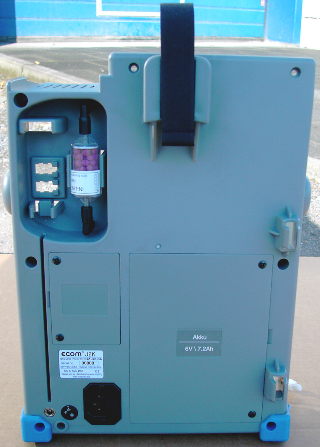
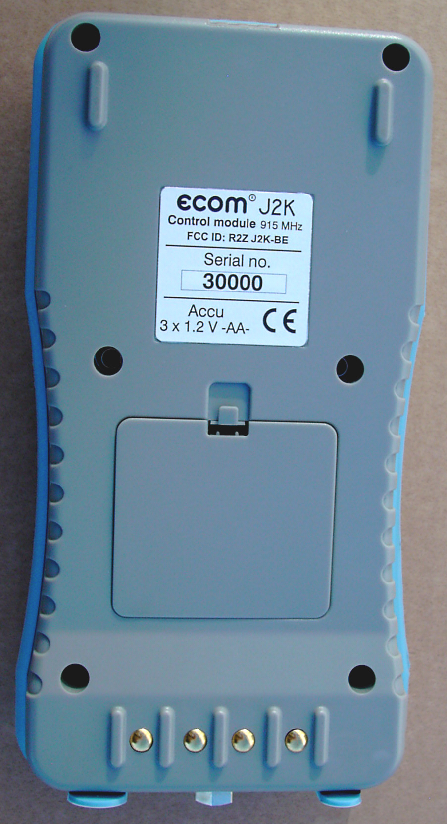
Annex No.1 Page 1 of 2 External Photographs of the Equipment Under Test EXTERNAL FRONT VIEW PHOTO Annex No.1 Page 2 of 2 EXTERNAL REAR VIEW PHOTO

ID Label/Location Info

Annex No.4 Page 1 of 2 FCC ID LABEL SAMPLE SKETCH OF FCC ID LABLE LOCATION Annex No.4 Page 2 of 2

Internal Photos

Annex No.2 Page 1 of 2 Internal Photographs of the Equipment Under Test INTERNAL UPPER SIDE PHOTO Annex No.2 Page 2 of 2 INTERNAL LOWER SIDE PHOTO

Operational Description

Annex No.5 Technical Description ecom ® J2K-BE ECOM America Ltd. 1628 Oakbrook Drive Gainesville, GA 30507 / USA 1. Application Field The instrument is suitable for energetical measurements and flue gas analysis at combustion plants fired with solid, gaseous and liquid fuel types according to the 1. BImSchV. The flua gas analyser ecom-J2K is designed a modular way and can be fitted with up to 5 electrochemical sensors (standard O2 and CO / optional NO, NO2 and SO2). The parameters sucking air temperature and gas temperature as well as chimney draught, an integral protocole printer and a sampling system with 2.2 m gas hose belong to the features of the standard version. 2. Design and Operation Principle A measurement gas pump sucks the gas continuously via a coaxial probe with double- pipes (internal pipe with thermoelement - gas and gas temperature; external pipe - chimney draught) or alternatively via a multi-holes pro- be and drives it thru a condensation trap, as well as particle and chemical filters to the electrochemical sensors. Flue Gas Analyser ecom-J2K Depending on the gas concentration, the measuring electrodes of the sensors issue electrons which are identified as current signals and processed. All electrochemical sensors are temperature-compensated within the operation field between +5 and + 40 ∞C. The measurement values can be converted internally on a free selectable O 2 reference value in concentration values in mg/m 3 and protocolable. A fresh air calibration (duration: 3 minutes) and an automatic system check occur generally by each switch-on procedure of the system. After the calibration phase, all measurement and calculation values are available. The measurement results are shown on the backlit graphics display. All relevant values can be displayed simultaneously. A zoom function enables the emphasized illustration of the mesurement values. The instrument consists of a compact basic module storing the measurement technique and of a removable control module. The control module enables the monitoring of the basic module via radio (frequency 915 MHz). The temperature sensor for combustion air analysis can either be connected to the control or to the basic module. The thermal printer, fitted in the standard version, is integrated into the basic module. The condensation trap, combined with an electronic position monitoring avoids the penetration of humidity. Additional protection againts humidity and condensation into the instrument is ascertained by an electrical measurement gas cooler and an automatic condensate evacuation sytem. The ecom-J2K also performs automatic dry soot tests with the optional heated pistol grip probe. As alterna- tive to the standard thermal printer a matrix printer is available as option. Instructions Manual ecom-J2K The calculated value shown on the line CO 0 % corresponds to themeasured CO concentration supposed the oxygen content wouldamount 0% by the same exhaust gas volume.It is consequently the undiluted CO content in exhaust gas. If the valueindication is stable, press the key <Memory> (disk symbol) to store the result in the intermediate memory. 6.3. Oxygen testThis measurement is performed by room-independant plants like grosscalorific value plants .It is determined if exhaust gas flows into the combustion air (O2content drops down) and herewith influence on the combustionquality.For this analysis a special multi-hole probe (optional accessory) shouldbe used. If the value indicated is stable, press the key <Memory> (disk symbol) to store the value in the intermediate memory. Measurement stored in intermediate memory O2 17.5 % CO 0% 738 ppm CO 123 ppm Excess air 7.00 CO measurement 12:15:53 25.11.03 stored! CO O2 19.5 % O2 in air Oxygen test 12:15:53 25.11.03 stored! CO Measurement stored in intermediate memory ecom-J2K Page 12 rbr Computertechnik GmbH Am Groflen Teich 2 D-58640 Iserlohn (S ̧mmern) Telefon: (49) 2371-945-5 Telefax: (49) 2371-40305 Internet: http://www.rbr.de eMail: [email protected] Index Page 1. Instrument design 1.1. Basic module 3 1.2. Control module 4 2. Power supply 5 3. Radio communication basic/control modules 64. Instrument switch on 7 5. Input or selection of combustion plants 8 6. Flue gas analysis 6.1. Gas analysis 10 6.2. CO mesurement (gas path check) 11 6.3. O2-Ringspaltmessung 12 6.4. Draught measurement 13 6.5. Soot dot...Oil trace 13 6.6. Measurement record and printout 15 7. Adjustments 16 8. Control 18 9. Data processing 18 10. Maintenance advices 20 11. Technical data 22 ecom-J2K Page 2 6.4. Draught measurementA trend indication for the draught conditions in the exhaust channelcan already be determined during the gas analysis. Nevertheless thevalue for the chimney draught will not be stored together with the gasvalues while pressing the key <Memory> . Indeed the difference pressure sensor tends to drifts because of itssensibility and, for an exact measurement, it is consequently advisedto re-calibrate the sensor immediately before sampling anddocumenting the value.. Access the menu while selecting the sub-menu "Draught measurement" . The current value is displayed as well as the instruction to adjust the zero point of the sensor.. Release hereto the draught hose from the instrument for a short moment and press <F4> . The sensor is herewith re-calibrated. . Fix the draught hose again. The display shows the exact measurement value which can be stored while pressing <Memory> and added to the previous results in the intermediate memory. The stored value is shown on the display.. Press <ESC> to quit the differential pressure measurement menu. 6.5. Soot...Oil traceThe sub-menu "Soot...Oil trace" enables the input of measured results for boiler temp-erature, soot dots and oil trace.. Select the line ÑBoiler temp.ì and press <OK> to activate the input. The input can be made using the numerical keys.. Press <OK> to store the value in the data record of the measurement.ecom-J2K Page 13 Soot..Oil traceBoiler temp. : 66∞C…

Text truncated - open the document above for the full version.

Test Report

Test Report No.: 04001953 Page 1 of 25 EUT : ecom ® J2K-BE (Control module) FCC ID: R2ZJ2K-BE Issue date: 2004-04-20 m. dudde hochfrequenz-technik Rottland 5a Vers. Datum:2002-12 D-51429 Bergisch Gladbach Tel. +49 2207-9689-0 Fax +49 2207 9689-20 e-mail: [email protected] http://www.dudde.com Test Report acc. to the relevant standard: 47 CFR Part 15 C – Intentional Radiators Measurement Procedure: ANSI C63.4 - 1992 relating to rbr Computertechnik GmbH Control module ecom ® J2K-BE Measurement of Radio- Noise Emissions from Low- Voltage Electrical and Electronic Equipment Technical characteristics and test methods for radio equipment in the frequency range 9 kHz to 40 GHz Test Report No.: 04001953 Page 2 of 25 EUT : ecom ® J2K-BE (Control module) FCC ID: R2ZJ2K-BE Issue date: 2004-04-20 m. dudde hochfrequenz-technik Rottland 5a Vers. Datum:2002-12 D-51429 Bergisch Gladbach Tel. +49 2207-9689-0 Fax +49 2207 9689-20 e-mail: [email protected] http://www.dudde.com Manufacturer’s details Manufacturer rbr Computertechnik GmbH Manufacturer’s grantee code Am Großen Teich 2 D-58640 Iserlohn (Sümmern) Phone: +49(0)2371 – 945 - 5 Fax: +49(0)2371 – 40305 eMail: [email protected] Manufacturer’s address 47 CFR Part 15C - Intentional Radiators Relevant standard used ANSI C63.4-1992 Test Report prepared by Ralf Trepper m.dudde hochfrequenz-technik (Labor) Rottland 5a D-51429 Bergisch Gladbach Germany Phone: +49 2207 96890 Fax : +49 2207 968920 Technical engineer E-mail: [email protected] Equipment Under Test (EUT) Equipment category Transceiver Trade name ecom ® Type designation ecom ® J2K-BE (Control module) Serial no. Device no. 1141 none Variants Test Report No.: 04001953 Page 3 of 25 EUT : ecom ® J2K-BE (Control module) FCC ID: R2ZJ2K-BE Issue date: 2004-04-20 m. dudde hochfrequenz-technik Rottland 5a Vers. Datum:2002-12 D-51429 Bergisch Gladbach Tel. +49 2207-9689-0 Fax +49 2207 9689-20 e-mail: [email protected] http://www.dudde.com 0 Test result CFR Section Report Chapter Requirements Headline Test result OK 15.203 10.1 Antenna requirement pass fail n.a. 15.249 (a) 10.2 Field strength limits (fundamental) pass fail n.a. 15.249(d) 15.209 10.2 Radiated spurious emissions pass fail n.a. 15.207 10.3 Conducted emissions pass fail n.a. 15.215 (c) 10.4 20 dB bandwidth pass fail n.a. Test requirements kept yes no . Signature test personnel ........................................ Ralf Trepper . Signature of the company official ......................................... Manfried Dudde Test Report No.: 04001953 Page 4 of 25 EUT : ecom ® J2K-BE (Control module) FCC ID: R2ZJ2K-BE Issue date: 2004-04-20 m. dudde hochfrequenz-technik Rottland 5a Vers. Datum:2002-12 D-51429 Bergisch Gladbach Tel. +49 2207-9689-0 Fax +49 2207 9689-20 e-mail: [email protected] http://www.dudde.com List of contents Page 0 Test result............................................................................................................................................. 3 1 Testing laboratory................................................................................................................................5 2 Introduction......................................................................................................................................... 5 3 Product................................................................................................................................................. 6 4 Test schedule........................................................................................................................................ 6 5 Product and measurement documentation......................................................................................... 7 6 Observations and comments................................................................................................................ 7 7 Summary.............................................................................................................................................. 7 8 Conclusions......................................................................................................................................... 8 9 Operation description.......................................................................................................................... 9 10.1 Antenna requirement...................................................................................................................... 10 10.1.1 Regulation ...................................................................................................................................... 10 10.1.2 Result ............................................................................................................................................. 10 10.2 Radiated emissions......................................................................................................................... 11 10.2.1 Regulation ...................................................................................................................................... 11 10.2.2 Test equipment ............................................................................................................................... 13 10.2.2 Test procedures............................................................................................................................... 13 10.2.3 Calculation of field strength Section 15.209 below 30 MHz ........................................................... 14 10.2.3 Calculation of field strength Section 15.209 above 30 MHz ........................................................... 14 10.2.4 Calculation of average correction factor.......................................................................................... 14 10.2.5 Calculation of the field strength Section 15.249.............................................................................. 15 10.2.6 Result ..................…

Text truncated - open the document above for the full version.

Test Report

Annex No.3 Page 1 of 1 OCCUPIED BANDWITH PLOT

Test Setup Photos

Annex No.6 Page 1 of 1 Test Setup Photos : ecom ® J2K-BE

Contact Information

Applicant

Siegfried Fischer(Engineer)
[email protected]0049 2371 945Fax: 0049 2371 40305

Technical Contact

m.dudde high frequency technologyRalf Trepper
[email protected]+49 2207 9689 0

Rottland 5A · Bergisch Gladbach · Germany

Test Firm

m. dudde hochfrequenz-technikManfred Dudde
[email protected]49-2207-9689-0Fax: 49-2207-9689-20

Technical Specifications

#Rule PartsFrequency RangePower Output
115C915 MHz - 915 MHz-
Confidentiality
Long Term

Other Applications from ecom GmbH

Flue gas analyser - FCC ID R2ZJ2K-BA - ecom GmbH
R2ZJ2K-BA

Flue gas analyser

May 27, 2004

Equipment Class

DXX - Part 15 Low Power Communication Device Transmitter