R3HWT202GMRS & FRS 2 Ways Radio
Daxian-Windsor Technology Limited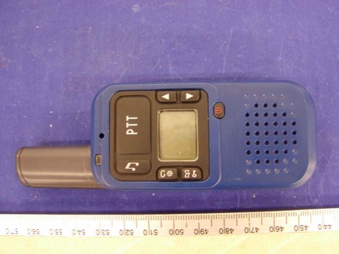
Click to zoom
Application Details
- Equipment Class
- FRF - Part 95 Family Radio Face Held Transmitter
- Date of Grant
- Jun 22, 2004
- Application Purpose
- Original Equipment
- Date of Application
- Jun 22, 2004
- Equipment Note
- GMRS & FRS 2 Ways Radio
- Frequency Range
- 462.56250000 - 467.72500000
- Country
- China
Documents & Files
Document Text
Text extracted from the exhibit documents filed with the FCC. Open a document above to read the original.
Users Manual
DWT_WT- 202_PMR_User’s Manual V.3 30 Mar., 2004. 1 / 6 462/ 467MHz GMRS & FRS 2-Way Radio Model: WT-202 FEATURES 1. 22 Channel – GMRS & FRS version 2. 38 CTCSS code 3. VOX ( 3 Levels of Sensitivity) 4. 10 Group Call Tone Selection 5. Key Lock 6. Scan 1. Transmit LED indicator 2. Microphone 3. Earphone and Wall Charger jack 4. Call Key 5. Scan / Monitor Key 6. Menu / Lock Key 7. PTT (Push To Talk) Key 8. Up Key 9. Down Key 10. Power On/Off Key 11. Speaker 12. Desktop Charger Pins (Desktop Charger is option accessory) 13. Detachable Belt Clip Hold (Belt Clip is option accessory) 14. Battery Cover DWT_WT- 202_PMR_User’s Manual V.3 30 Mar., 2004. 2 / 6 Battery Installation 1. Press the battery door knob to take off the battery door. 2. Follow × “This side up” and +/- direction to install the Li-ION battery pack into the compartment. 3. Replace the battery door. Warning: A. Reverse the polarities of battery would damage the unit and the battery. B. Do not replace the battery with other brand name or type of battery, otherwise, the unit will not work or be damage. C. When battery level low, recharge the battery with the adaptor or desk top charger enclosed. Do not use other brand name or type of charger to recharge the battery, otherwise, the unit & battery will be damage. D. If you’re not going to use the unit for a long period of time e.g several weeks, please take out the battery. Otherwise, it will erode and damage the battery. E. When battery damaged or not working, disposed it safely. Never turn them or put them close to heart, otherwise, it may cause explosion. Power On / Off the unit To power on the radio, press Power On/Off Key for 3 seconds until hear a beep and LCD display the Channel no. and battery level icon. To power off the radio, press Power On/Off Key for 3 seconds until LCD display turn off. DWT_WT- 202_PMR_User’s Manual V.3 30 Mar., 2004. 3 / 6 Menu Flow chart Menu Main channel CTCSS Call tone VOX sensitivity VOX overtime Note: Press PTT Key to confirm and escape. MAKING COMMUNICATIONS The Radio has 22 main channels & 38 CTCSS code. You can communicate with any other user who is using the same main channel. Speak to other radio 1. Press & hold the PTT key, transmit LED turn on. 2. Hold the unit in a vertical position with the Microphone 5-8cm from the mouth and then speak 3. When you finish speaking, release the PTT key and you will hear a beep tone. Listen to other radio 1. When you press the PPT key, you can not listen to other radio. Make sure you do not press the PTT key for listening. 2. Adjust volume control if necessary. ADJUSTING SPEAKER VOLUME (8 level) 1. Press the “▲”button to increase the volume. 2. Press the “▼”button to decrease the volume. OVERTIME FUNCTION 1. Overtime function can avoid transmitting by chance and to prolong the battery life. 2. The radio will end to transmit and utter a warning tone when PTT is held over 60 seconds. You then need to release PTT and press it again for further transmission. 3. In VOX mode, the unit will stop transmitting and utter a warning tone after continuing talk for 60 seconds. You can re-activate VOX after the overtime stop. (Please refer to VOX function for details VOX operation) SELECT CHANNEL You can communicate with any other user who is using the same channel. To set the main channel 1. Press the “menu” key once, the channel number display will flash, 2. Press “▲”, “▼” key to select your desired main channel. 3. Press the “PTT” key to confirm, the channel number display will stand. DWT_WT- 202_PMR_User’s Manual V.3 30 Mar., 2004. 4 / 6 CTCSS code function This function can help you to identify your group of users among the same channel. Only the users with the same CTCSS tone can listen and talk to each other, but all the users on the same channel can listen to the conversation. To select a CTCSS code 1. Press the “menu” key twice , the CTCSS code display will flash, 2. Press “▲”, “▼” key to select your desired the CTCSS code (1~38, “0” is off) 3. Press the “PTT” key to confirm, the CTCSS code display will stand. SCANNING CHANNEL 1. Press “Scan / Monitor” Key, LCD display icon. It will start to scan channel automatically. Note: If press and hold the button over 2 seconds, it will break the squelch noise and listen to the current channel. 2. The unit scans all channels one by one it will stay on the occupied channel. Press “▲”Key to continue scanning. 3. If there is no signal, it will continue to scan. Press PTT key, it will stay on the current channel and continue to scan after 5 seconds. 4. Press “Scan/Mon” Key to quit and return to current channel. Note: Occupied Channel means main channel and CTCSS code are same. TALK RANGE It is a unique design, excellent performance and good communication range Radio. The communication range is excellent in open field and is vary in different environment: Optimal Range – range up to 3 km in open field Medium Range – reduced range in area with obstacle of trees, houses. Shortest Range – further reduced range in dense forest, high mountain, tall building area. Warning - Do not transmit within 1.5 meter among other radio because of interference. SENDING CALL TONES You can use Call Tones to get the attention of other people with radios on the same channel and CTCSS tone. You can also use Call Tones as the signal of the start or end of a transmission. 1. Press “CALL” key, LCD display icon and your call tone will be transmitted to nearby receivers set at the same channel. 2. The call tones have 10 kinds of sound for personal selection. Select call tones 1. Press “MENU” key three times, LCD display icon and call tone number will flash, 2. Press “▲”, “▼”key to select your desired the call tone DWT_WT- 202_PMR_User’s Manual V.3 30 Mar., 2004. 5 / 6 3. Press the “PTT” Key to confirm, the call tone number display will stand. VOX - HANDS-FREE FUNCTION The Radio has a built-in Voice Activated Circuit (VOX) function. You can connect the radio with the earphone for hands-free talking and list…
Text truncated - open the document above for the full version.
External Photos
Daxian-Windsor Technology Limited FCC ID: R3HWT202 APPENDIX C - EUT PHOTOGRAPHS Chassis - Front View Chassis – Rear View
Operational Description
Daxian-Windsor Technology Ltd. 08 Feb., 2004 WT202 Circuit Description DC Power distribution The DC output is regulated to 3V by 3V-REG. It should provide 20dB or more isolation from power supply noise, making the 3V power line is used for all digital circuits and analog lines. The power control loop T3V and R3V is control the by the MCU asserting the transmitter or receiver. PLL Synthesizer Heart of the synthesizer is the VCO which supplies RX and TX as well. A helix coil guarantees low oscillator phase noise, the VCO works on half the receiving injection frequency and the transmission frequency, to decouple it from interference by the power amplifier and avoids feedback loop signals. A doubler follows the VCO, which again is followed by a match-network between the stages gives some additional isolation. In the collector circuit of the buffer a notch filter is used to suppress the VCO frequency. The VCO are switched between the TX and the RX modes with switching transistor and pin diode, in the RX mode L.OSC runs 21.4MHz below the receive frequency. The reference oscillator is 20.95MHz it also used to drive the second receiver mixer. The synthesizer chip TB31202 control the VCO, the current source of the internal phase detector is drives the low-impedance loop filter. Two-Point Modulation The single-point modulation scheme is low-frequency content limited by the PLL loop-filter. To achieve better CDS low bit ratio data and CTCSS sub-audio frequency response, the device, provides signal to both the VCO and PLL reference oscillator together, this results in the low frequency content that is within the loop bandwidth. Receiver The antenna is connected to the receiver’s front-end via the low-pass filter and T/R PIN switch. 2 pole L.C. band-pass filter reduces some of the broad-band noise and interference. LNA amplifies the signal about 18dB, and then a SAW filter follows. Image responses should be down 56 or more dB with this line up. A 2SC4226 transistor acts as mixer to obtain a good intermodulation response, the base are driven with the receive signal and the RX VCO local oscillator signal (low-side injected). The output of the mixer is applied to a 21.4 MHz crystal filter that provides the first IF channel filtering. An IF/Demod chip the MC3361. This chip converts the signal to 450KHz, external ceramic filters further reduce adjacent channel interference, and then the FM is demodulated with a quadrature detector. The MC3361 also amplified, filtered, and rectified by a noise amp. The DC level proportional to the noise is compared to a digitally set squelch threshold by MCU-EM78566 port-P70. PDF created with FinePrint pdfFactory Pro trial version www.pdffactory.com Daxian-Windsor Technology Ltd. 08 Feb., 2004 The RX voice signals are via a High Pass Filter amplifier to the final Audio PA, both amplifier reject the sub-audio signals (0~250.3Hz) about 36dB. The RX CTCSS / CDS sub-audio signals pass-through the post amplifier to the MCU A/D-Port P93, the micro controller provides software filtering to avoids higher than 250.3Hz unwanted signals. Transmitter The TX voice signals are also processing by two operation amplifier it is consist of limiter, pre-emphasizer and harmonic filter, the voice output signals mixing the sub-audio signals to the VCO and PLL reference oscillator. The driver 2SC4226 boosts the VCO signal up by 20dB gain. This is sufficient to drive the RF PA 2SK3078A which at 3.7V power supply voltage delivers an output power of 0.5 Watt. 30mS after switching the VCO to the TX mode, the RF power control loop T3V is enable by the MCU asserting the transmitter on, the slow ramping of the transmitter avoids spurious signals in the adjacent channels. Micro Controller Unit A MCU EM78566 is used to control the whole radio. It polls the PTT and VOX line, sub-audio signals filtering, CTCSS / CDs codes generation and detection, and CTCSS Reverse Burst, programs the PLL synthesizer chip, switches receiver and transmitter path in a well defined time scheme and select or checks the channels, checks battery levels etc. PDF created with FinePrint pdfFactory Pro trial version www.pdffactory.com
Test Report
Note: This test report is specially limited to the above client company and product model. It may not be duplicated without prior written consent of Bay Area Compliance Laboratory Corporation. This report must not be used by the client to claim product endorsement by NVLAP or any agency of the U.S. Government. FCC PART 95 EMI MEASUREMENT AND TEST REPORT For Daxian-Windsor Technology Limited Rm 12, 2/F., Hung Tai Ind Bldg., 37-39 Hung To Road, Kwun Tong, Hong Kong FCC ID: R3HWT202 This Report Concerns: Original Report Equipment Type: GMRS Radio Test Engineer: Ling Zhang / Report Number: R0404096 Report Date: 2004-05-02 Reviewed By: Ming Jing / Prepared By: Bay Area Compliance Laboratory Corporation 230 Commercial Street Sunnyvale, CA 94085 Tel: (408) 732-9162 Fax: (408) 732 9164 Daxian-Windsor Technology Limited FCC ID: R3HWT202 Report # R0404096Rpt.doc FCC Part 95 Test Report Page 2 of 26 TABLE OF CONTENTS GENERAL INFORMATION.......................................................................................................................................4 PRODUCT DESCRIPTION FOR EQUIPMENT UNDER TEST (EUT) ....................................................................................4 OBJECTIVE...................................................................................................................................................................4 RELATED GRANT/SUBMISSION.....................................................................................................................................4 TEST METHODOLOGY..................................................................................................................................................4 TEST FACILITY.............................................................................................................................................................4 SYSTEM TEST CONFIGURATION ..........................................................................................................................6 JUSTIFICATION.............................................................................................................................................................6 EUT TEST CONFIGURATION........................................................................................................................................6 SPECIAL ACCESSORIES.................................................................................................................................................6 SCHEMATICS / BLOCK DIAGRAM.................................................................................................................................6 EQUIPMENT MODIFICATIONS.......................................................................................................................................6 CONFIGURATION OF TEST SYSTEM..............................................................................................................................6 TEST SETUP BLOCK DIAGRAM.....................................................................................................................................7 REQUIREMENTS OF PROVISIONS ........................................................................................................................8 §2.1046, §95.639(D), AND §95.639 (A)(1) - EFFECTIVE RADIATED POWER ....................................................9 STANDARD APPLICABLE..............................................................................................................................................9 TEST PROCEDURE........................................................................................................................................................9 TEST EQUIPMENT.......................................................................................................................................................10 ENVIRONMENTAL CONDITIONS..................................................................................................................................10 TEST RESULTS...........................................................................................................................................................10 §2.1046, §95.639(D), AND §95.639 (A)(1) – CONDUCTED OUTPUT POWER ...................................................12 5.1 PROVISION APPLICABLE.......................................................................................................................................12 5.2 TEST PROCEDURE................................................................................................................................................12 5.3 TEST EQUIPMENT.................................................................................................................................................12 5.4 TEST RESULTS.....................................................................................................................................................12 §2.1047, §95.631(D), §95.637(A), AND § 95.637(B) - MODULATION CHARACTERISTICS ...........................14 STANDARD APPLICABLE............................................................................................................................................14 TEST PROCEDURE......................................................................................................................................................14 TEST EQUIPMENT.......................................................................................................................................................14 ENVIRONMENTAL CONDITIONS..................................................................................................................................15 TEST RESULTS...........................................................................................................................................................15 §2.1049, §95.633(A), AND § 95.…
Text truncated - open the document above for the full version.
Test Report
Daxian-Windsor Technology Limited FCC ID: R3HWT202 APPENDIX B - TEST SETUP PHOTOGRAPHS Radiated Emission - Front View Radiated Emission - Rear View
Test Setup Photos
Daxian-Windsor Technology Limited FCC ID: R3HWT202 APPENDIX B - TEST SETUP PHOTOGRAPHS Radiated Emission - Front View Radiated Emission - Rear View
Contact Information
Applicant
Eva Yuen(Director)
Test Firm
Bay Area Compliance LaboratoryJohn Chan
Technical Specifications
| # | Rule Parts | Frequency Range | Power Output | Emission | Tolerance |
|---|---|---|---|---|---|
| 2 | 95A | 462.5625 MHz - 467.725 MHz | 309.00 mW | 11K0F3E | 2.5 ppm |