R3STPB-C01Pano Computer
Topeak, Inc.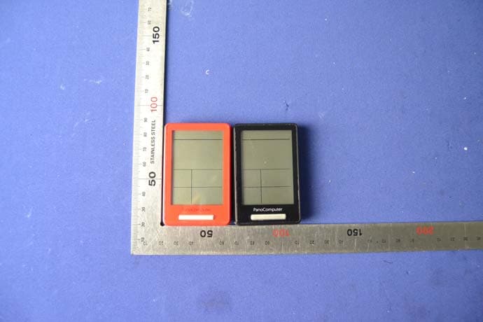
Click to zoom
Application Details
- Equipment Class
- DXX - Part 15 Low Power Communication Device Transmitter
- Date of Grant
- Jun 30, 2014
- Application Purpose
- Original Equipment
- Date of Application
- Jun 30, 2014
- Equipment Note
- Pano Computer
- Frequency Range
- 2402.00000000 - 2480.00000000
- Company
- Topeak, Inc.
- Country
- Taiwan
Documents & Files
Document Text
Text extracted from the exhibit documents filed with the FCC. Open a document above to read the original.
Users Manual
for 6 sec to return to COMPUTER MODE after riding. for 6 sec to switch. ( 3 sec to clear and reset all data) for 6 sec to return to COMPUTER MODE. On computer for 6 sec to enter CLONE MODE. to enter each setting mode. to change digit. to next selection. Keep following the & processes for the rest of setting then to confirm . Follow the procedure in each section to set up your computer: GB PanoComputer Wireless User's Guide • PanoComputer data syncs with Topeak PanoBike App only. • Please read all instructions before first use! • Before riding, close the PanoBike App on your smart device to record ride data in Computer Mode. PanoComputer Mount (Fits ø 31.8 mm Handlebar only) Bolt SET Button RESET ButtonMODE Button PressPress and Hold OPERATION SYMBOLS REQUIRED ACCESSORIES HOW TO SET UP YOUR PANOCOMPUTER HOW TO OPERATE IN CLONE MODE (SECOND MONITOR function) (Using English version as an example) 6 sec Data syncs with computer Start riding... Please download and install Topeak PanoBike App from Apple App Store or GooglePlay to your smart device first. Tap II to stop and save ride data to your smart device. 1 sec: select digit 3 sec: go to next section / into setting mode 6 sec: switch COMPUTER MODE and CLONE MODE. OPTION A [ COMPUTER MODE ] | OPERATE THE COMPUTER Confirm Turn the crankarm counterclockwise. When "1" appears, the Speed & Cadence Sensor pairing is successful. Note: Bike B will indicate "2". Wear the Heart Rate Monitor on your chest. When "1" appears, the pairing is successful. Note: Bike B will indicate "2". 3 sec3 sec BIKE A.BDate12/ 24h clockkm/ mODO Wheel Circumference Pairing Speed & Cadence Sensor + Heart Rate Monitor SCREEN DISPLAY (RIDING STATUS) (COMPUTER MODE ONLY) If no button is touched for 10 seconds, the screen will switch to Screen 1 automatically. Screen 1Screen 2Screen 3 3 sec 3 sec to save ride data to check the ride data just saved. SAVING RIDING DATA (COMPUTER MODE ONLY) PAIRING SPEED & CADENCE SENSOR + HEART RATE MONITOR Ride data is transmitted to computer from smart device. Smart device screen can be turned o to save battery. OPTION B [ CLONE MODE ] | SETTING THE COMPUTER WITH PANOBIKE APP (Using English version as an example) Open PanoBike App in your smart device then tap “ ” icon. 6 sec Tap "Setup" button to pair smart device with computer. Choose desired time and unit format. Insert power zones and wheel size setting. Tap "Save" to complete. Follow the pairing procedures to pair Speed & Cadence Sensor and Heart Rate Monitor as in OPTION A. PanoComputer includes “DUAL MODE” function Sensors transmit ride data to PanoBike App on your smart device and displays ride data on computer. Smart device screen is turned off to save battery. [ COMPUTER MODE ] Sensors transmit ride data to computer directly. After riding, data can be transferred to PanoBike App on your smart device. [ CLONE MODE ] 1234 On computer for 6 sec to enter CLONE MODE. Open Topeak PanoBike App. Tap "START RIDE", then tap "START" to record your ride. 123 PanoBike Speed & Cadence Sensor PanoBike Heart Rate Monitor Art No. TPB-HRM01Art No. TPB-CS01 On computer for 6 sec to enter CLONE MODE. Copyr ight © Topeak, I nc. 2014 M-TPB-C01-GB 04/14 PanoComputer Wireless User's Guide Battery < 2.7 V LOW BATTERY 2-year Warranty: All electronic and mechanical components against manufacturer defects only. Batteries are not covered under any implied warranty. Warranty Claim Requirements To obtain warranty service, you must have your original sales receipt. Items returned without a sales receipt will assume that the warranty begins on the date of manufacture. All warranties will be void if the product is damaged due to user crash, abuse, system alteration, modification, or used in any way not intended as described in this manual. * The specifications and design are subject to change without notice. Please contact your Topeak dealer with any questions. For USA customer service, call: 1-800-250-3068 Website: www.topeak.com WARRANTY * “Current Cadence” Requires optional PanoBike Speed & Cadence Sensor. * “Current Heart Rate” Requires optional PanoBike Heart Rate Monitor. * Wheel circumference default: 2235 mm DISPLAYFUNCTION Current Speed Average Speed Maximum Speed Trip Distance Accumulated Distance Ride Time Accumulated Ride Time Low Batt ery Indicator 12H/ 24H clock Bike A and Bike B INCREMENTSSPECIFICATIONSACCURACY 0.1 km/h or mi/h 0.1 km/h or mi/h 0.1 km/h or mi/h 0.1 km or m 0.1 km or m 1 Second 1 Minute 1 Minute 199 km/h, 199 mi/h 199 km/h, 199 mi/h 199 km/h, 199 mi/h 0.00~9999.99 km or m 0.00~99999.9 km or m 0 : 00 : 00~99 : 59 : 59 0000 : 00~9999 : 59 < 2.7 V Current Cadence * 0~199 RPM 0~199 BPM Current Heart Rate * Bluetooth® System SmartPhone Connected 1 : 00 ~12 : 59 (12 H) 0 : 00 ~23 : 59 (24 H) 1 % 0.1 % 0.1 % 0.1 % 0.1 % 0.1 % 0.1 % 0.003 % ± ± ± ± ± ± ± ± Pace Indicator SPECIFICATION Tech: Bluetooth® Smart (BLE 4.0) super low energy technology Mount: Handlebar Mount (ø 31.8 mm only) Battery Lifetime (max.): 360 hours (1 hr/ day use) * Battery: CR2032 x 1 pc (included) Transmission Range: <10 meter (33 ft) Waterproof: IPX 7 Operating temperature: -10°C ~ 50°C (14°F~122°F) Weight: 30 g / 1.06 oz (computer only) IMPORTANT NOTE CLEAR ALL DATA SETTING will clear all stored data. CLEAR ALL DATA SETTING is required during FIRST SETUP or BATTERY CHANGE. All data will be cleared when replacing the battery. Before changing battery, write down stored data ODO and ART. The TOPEAK PANOCOMPUTER can be used in the rain but should not be intentionally submerged underwater. Do not leave the computer exposed to direct sunlight when not riding the bicycle. Do not disassemble the computer body or its accessories. Check relative positions and gap between sensor and magnet periodically. Do not use harsh chemicals to clean the computer body or its accessories. Remember to pay attention to the road while riding. Check the computer mount before each ride to ensure a secure connection. Dispose of used batteries acco…
Text truncated - open the document above for the full version.
Users Manual
FCC INFORMATION This device complies with Part 15 of the FCC Rules. Operation is subject to the following two conditions: 1. This device may not cause harmful interference, and 2. This device must accept any interference received, including interference that may cause undesired operation. Note: This equipment has been tested and found to comply with the limits for a Class B digital device, pursuant to part 15 of the FCC Rules. These limits are designed to provide reasonable protection against harmful interference in a residential installation. This equipment generates, uses and can radiate radio frequency energy and, if not installed and used in accordance with the instructions, may cause harmful interference to radio communications. However, there is no guarantee that interference will not occur in a particular installation. If this equipment does cause harmful interference to radio or television reception, which can be determined by turning the equipment off and on, the user is encouraged to try to correct the interference by one or more of the following measures: —Reorient or relocate the receiving antenna. —Increase the separation between the equipment and receiver. —Connect the equipment into an outlet on a circuit different from that to which the receiver is connected. —Consult the dealer or an experienced radio/TV technician for help. Caution: Any changes or modifications not expressly approved by the party responsible for compliance could void the user's authority to operate this equipment.
External Photos
Report No.: C140327Z03-RP1 Page 1/2 External Photos of EUT Report No.: C140327Z03-RP1 Page 2/2
ID Label/Location Info
11.8 mm 7.9 mm FCC ID : R3S TPB-C01 NCC ID : XXXXXXXX KC ID : XXXXXXXX TELEC ID : XXX-XXXXXX MODEL : TPB-C01 MADE IN TAIWAN FCC ID : R3S TPB-C01 NCC ID : XXXXXXXX KC ID : XXXXXXXX TELEC ID : XXX-XXXXXX MODEL : TPB-C01 MADE IN TAIWAN
Internal Photos
Report No: C140327Z03-RP1 Internal Photos of EUT Report No: C140327Z03-RP1 Report No.: C140327Z03-RP1 Page 3/3
Test Report
Report No.: C140327Z03-RP1 FCC ID: R3STPB-C01 Page 1/30 This report shall not be reproduced except in full, without the written approval of Compliance Certification Services. FCC 47 CFR PART 15 SUBPART C for Pano Computer Model: TPB-C01 Brand: TOPEAK Test Report Number: C140327Z03-RP1 Issued for Topeak, Inc. 8F-4, No.20, Dalong Road, Taichung, Taiwan (40310) Issued by: COMPLIANCE CERTIFICATION SERVICES (SHENZHEN) INC. No.10-1, Mingkeda Logistics Park, No.18, Huanguan South Rd., Guan Lan Town, Baoan District, Shenzhen, China TEL: 86-755-28055000 FAX: 86-755-28055221 Issued Date: April 9, 2014 Note: This report shall not be reproduced except in full, without the written approval of Compliance Certification Services Inc. This document may be altered or revised by Compliance Certification Services Inc. personnel only, and shall be noted in the revision section of the document. The client should not use it to claim product endorsement by TAF, A2LA, NVLAP, NIST or any government agencies. The test result of this report relate only to the tested sample identified in this report. 检 测 CNAS L4818 Report No.: C140327Z03-RP1 FCC ID: R3STPB-C01 Page 2/30 This report shall not be reproduced except in full, without the written approval of Compliance Certification Services. Revision History Rev. Issue No. Revisions Effect Page Revised By 00 C140327Z03-RP1 Initial Issue ALL Sabrina Wang Report No.: C140327Z03-RP1 FCC ID: R3STPB-C01 Page 3/30 This report shall not be reproduced except in full, without the written approval of Compliance Certification Services. TABLE OF CONTENTS 1 TEST CERTIFICATION ...........................................................................................4 2 EUT DESCRIPTION.................................................................................................5 3 TEST METHODOLOGY...........................................................................................6 3.1. DESCRIPTION OF TEST MODES.......................................................................................6 4 TEST METHODOLOGY...........................................................................................7 4.1. EUT EXERCISE ...................................................................................................................7 4.2. FCC PART 15.205 RESTRICTED BANDS OF OPERATIONS............................................7 5 INSTRUMENT CALIBRATION ................................................................................8 6 SETUP OF EQUIPMENT UNDER TEST .................................................................8 6.1. DESCRIPTION OF SUPPORT UNITS .................................................................................8 6.2. CONFIGURATION OF SYSTEM UNDER TEST..................................................................8 7 FACILITIES AND ACCREDITATIONS ....................................................................9 7.1. FACILITIES ..........................................................................................................................9 7.2. ACCREDITATIONS ..............................................................................................................9 7.3. MEASUREMENT UNCERTAINTY .......................................................................................9 8 FCC PART 15.249 REQUIREMENTS ...................................................................10 8.1. BAND EDGES MEASUREMENT .......................................................................................10 8.2. POWER LINE CONDUCTED EMISSIONS MEASUREMENT ...........................................13 8.3. SPURIOUS EMISSIONS MEASUREMENT .......................................................................20 Report No.: C140327Z03-RP1 FCC ID: R3STPB-C01 Page 4/30 This report shall not be reproduced except in full, without the written approval of Compliance Certification Services. 1 TEST CERTIFICATION Product Pano Computer Model TPB-C01 Brand TOPEAK Tested March 27~April 8, 2014 Applicant Topeak, Inc. 8F-4, No.20, Dalong Road, Taichung, Taiwan (40310) Manufacturer Maxwell Guider Technology Rm., 4E07, No.5, Hsin Yi Rd.,Sec.5, Hsin Yi Dist.,Taipei City,Taiwan APPLICABLE STANDARDS STANDARD TEST RESULT FCC 47 CFR Part 15 Subpart C No non-compliance noted DEVIATION FROM APPLICABLE STANDARD None We hereby certify that: The above equipment was tested by Compliance Certification Services Inc. The test data, data evaluation, test procedures, and equipment configurations shown in this report were made in accordance with the procedures given in ANSI C63.4:2009 and the energy emitted by the sample EUT tested as described in this report is in compliance with the requirements of FCC Rules Part 15.207, 15.209, 15.249. The test results of this report relate only to the tested sample EUT identified in this report. Approved by: Reviewed by: Sunday Hu Supervisor of EMC Dept. Compliance Certification Service Inc. Ruby Zhang Supervisor of Report Dept. Compliance Certification Service Inc. Report No.: C140327Z03-RP1 FCC ID: R3STPB-C01 Page 5/30 This report shall not be reproduced except in full, without the written approval of Compliance Certification Services. 2 EUT DESCRIPTION Product Pano Computer Model TPB-C01 Brand TOPEAK Model Discrepancy N/A Identify Number C140327Z03-RP1 Power Supply DC3V supplied by the battery Frequency Range 2402-2480 MHz Transmit Power Peak: 89.49dBuV/m (Max.) Average: 91.06dBuV/m (Max.) Modulation Technique GFSK Number of Channels 40 Channels Antenna Specification PCB Antenna with 0dBi gain(MAX) Temperature Range 0°C ~ +40°C Note: 1. The sample selected for test was engineering sample that approximated to production product and was provided by manufacturer. 2. This submittal(s) (test report) is intended for FCC ID: R3STPB-C01 filing to comply with Section 15.207, 15.209 and 15.249 of the FCC Part 15, Subpart C Rules. Report No.: C140327Z03-RP1 FCC ID: R3STPB-C01 Page 6/30 This report shall not be reproduced except in full, …
Text truncated - open the document above for the full version.
Test Setup Photos
Report No.: C140327Z03-RP1 FCC ID: R3STPB-C01 Page 1/1 PHOTOGRAPHS OF THE TEST CONFIGURATION RADIATED EMISSION TEST Below 1GHz Above 1GHz
Contact Information
Applicant
Mike Chen(Product Manager)
Technical Contact
Test Firm
Compliance Certification Services (Shenzhen) Inc.Harry Li
Technical Specifications
| # | Rule Parts | Frequency Range | Power Output |
|---|---|---|---|
| 1 | 15C | 2.40 GHz - 2.48 GHz | - |