FCCID.CO- FCC ID Database
HomeCompaniesEquipment ClassesSearch

© 2026 FCC ID Database. All rights reserved.

AboutContactData sourced from FCC public records
  1. Home/
  2. Embedded Wireless Labs Sdn Bhd/
  3. R42MPES1

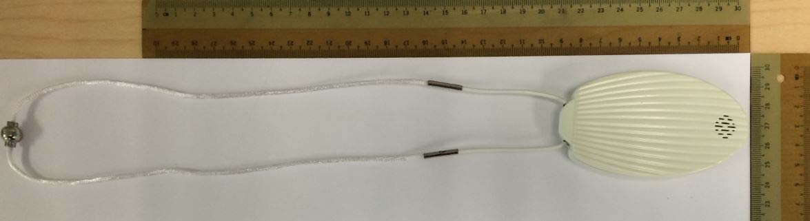
R42MPES1portable neck-worn wireless activity monitor device

Embedded Wireless Labs Sdn Bhd
portable neck-worn wireless activity monitor device - FCC ID R42MPES1 - Embedded Wireless Labs Sdn Bhd
Click to zoom

Application Details

Equipment Class
DTS - Digital Transmission System
Date of Grant
Jan 19, 2015
Application Purpose
Original Equipment
Date of Application
Jan 15, 2015
Equipment Note
portable neck-worn wireless activity monitor device
Frequency Range
2412.00000000 - 2462.00000000
Company
Embedded Wireless Labs Sdn Bhd
Country
Malaysia

Documents & Files

Select a file to view
Users Manual

↗

Attestation Statements

↗
↗
↗
↗

Cover Letter(s)

↗
↗

External Photos

↗

ID Label/Location Info

↗

Internal Photos

↗

RF Exposure Info

↗
↗
↗
↗

Test Report

↗

Test Setup Photos

↗

Document Text

Text extracted from the exhibit documents filed with the FCC. Open a document above to read the original.

Users Manual

1 Quick Start Guide (Beta) FCC ID: R42MPES1 Model Number: MPES1 2 Contents Inside the Box ........................................................................................................................................ 5 Activate Pendant ................................................................................................................................... 6 SOS Call .................................................................................................................................................. 8 Reminder ............................................................................................................................................... 9 Charging Pendant ................................................................................................................................ 10 SAR accessory....................................................................................................................................................11 3 Wireless Safety and Compliance Turn wireless off in areas where wireless use is forbidden or when it may cause interference or danger. Some specific situations are described below. In general, you should not use your Device with wireless turned on any place you are not allowed to use a cellular device. Be Careful Around Other Electronic Devices The Device generates, uses, and can radiate radio frequency (RF) energy and, if not used in accordance with its instructions, may cause harmful interference to radio communications and electronic equipment. External RF signals may affect improperly installed or inadequately shielded electronic operating systems, entertainment systems and personal medical devices. While most modern electronic equipment is shielded from external RF signals, if in doubt, check with the manufacturer. For personal medical devices (such as pacemakers and hearing aids), consult with your physician or the manufacturer to determine if they are adequately shielded from external RF signals. Steps to Minimize Interference If your Device does cause harmful interference to radio or television reception (which you can determine by turning your Device off and on), you can try to correct the interference by one or more of the following measures: reorient or relocate the receiving antenna for the radio or television; increase the separation between the radio or television and your Device; connect equipment and receivers to different outlets; or consult the radio or television manufacturer or an experienced radio/TV technician for help. Information regarding Exposure to Radio Frequency Energy Exposure to Radio Frequency Energy Your Device is designed and manufactured not to exceed the emission limits for exposure to RF energy set by the Federal Communications Commission of the United States (FCC) if installed with the provided SAR accessory as described within this quick guide, providing for a minimum distance of 10mm towards your chest, when worn with the lanyard which is the intended operating position. Information on your Device is on file with the FCC and can be found under the Display Grant section of http://www.fcc.gov/oet/ea/ after searching on the FCC ID for your Device, which can be found inside the battery compartment of the Device. Regulatory Statements The product must be set up and operated strictly according to manufacturer’s instructions included in the user documentation provided with the product. All changes and modifications must be expressly approved by the manufacturer. Failure to do so may nullify the user’s authority to operate the product. The manufacturer and its authorized resellers and distributors will assume no responsibility for damage from any failure to comply with these guidelines. FCC Compliance Statement for Model Number MPES1, FCC ID: R42MPES1 This Device complies with part 15 of the FCC rules. Operation is subject to the following two conditions: (1) This Device may not cause harmful interference; and (2) this Device must accept any interference received, including interference that may cause undesired operation. This Device has been tested and found to comply with the limits for a Class B digital device, pursuant to part 15 of the FCC rules. These limits are designed to provide reasonable protection against harmful interference in a residential installation. However, there is no guarantee that interference will not occur in a particular installation. 4 This Device meets the FCC Radio Frequency Emission Guidelines and is certified with the FCC as the FCC ID number found inside the battery compartment of the Device. Important: Changes or modifications to the Device not expressly authorized by Company could void your authority to operate the Device. 5 Inside the Box Pendant with lanyard Quick Start Guide 2 Batteries Warranty & Legal Information 1 in pendant 1 in charger 1 Charger SAR ACCESSORY 6 Activate Pendant 1. Remove the battery cover 2. Remove Battery 3. Remove the yellow layer that is covering the silver terminals Press your thumb gently on the back cover and slide upwards Push the tip of the cover and lift it up to remove Place you finger in the hollow section (As shown above) Lift the battery up to remove 7 4. Insert Battery 5. Pendant will vibrate to indicate battery is inserted properly. 6. Pendant will continuously vibrate for 23 seconds with intermittent pauses. 7. Pendant will proceed to stand–by mode once connection is established and plays ‘Pendant is going to stand-by mode’ message. Place the battery downwards with the golden terminals facing the pendant’s golden terminals (Top right corner as shown above) Gently press the bottom end of battery to secure the battery in place. 8 SOS Call 1. Hold the Pendant and close your fist around the Pendant for 5 seconds to make a SOS call (as shown below). 2. The Pendant will vibrate for 25 seconds and play ‘Emergency call, please grab and hold the Pendant for 1 second to cancel the emergency call’ message…

Text truncated - open the document above for the full version.

External Photos

Embedded Wireless Model: MPES1 FCC ID: R42MPES1

Internal Photos

Embedded Wireless Model: MPES1 FCC ID: R42MPES1

RF Exposure Info

FCC Listed #: A2LA Accredited IC Recognized # 3462B-1 CETECOM Inc. 411 Dixon Landing Road  Milpitas, CA 95035  U.S.A. Phone: + 1 (408) 586 6200  Fax: + 1 (408) 586 6299  E-mail: [email protected]  http://www.cetecom.com CETECOM Inc. is a Delaware Corporation with Corporation number: 2905571 V5.2 2013-02-15 © Copyright by CETECOM SAR Test Report FOR: Manufacturer: Embedded Wireless Model Number: MPES1 FCC ID: R42MPES1 Test Report #: SAR_EMBED_019_14001_FCC Date of Report: December 12, 2014 Test Report #: SAR_ EMBED_019_14001_FCC FCC ID: R42MPES1 Date of Report: December 12, 2014 Page 2 of 24 V5.1 2013-01-09 This report shall not be reproduced except in full without the written approval of: CETECOM Inc.  SAR  411 Dixon Landing Road  Milpitas, CA 95035  U.S.A. TABLE OF CONTENTS 1. Assessment ................................................................................................................................................... 4 2. Administrative Data .................................................................................................................................... 5 2.1. Identification of the Testing Laboratory Issuing the SAR Test Report ....................................... 5 2.2. Identification of the Client ................................................................................................................ 5 2.3. Identification of the Manufacturer .................................................................................................. 5 Same as client ............................................................................................................................................... 5 3. Equipment under Test (EUT) .................................................................................................................... 6 3.1. General Specification of the Equipment under Test ...................................................................... 6 3.2. Antenna Information ......................................................................................................................... 7 3.3. Technical Specification of Supported Radios .................................................................................. 7 3.4. Identification of the Equipment Under Test (EUT) ....................................................................... 8 3.5. Identification of Accessory equipment ............................................................................................. 8 3.6. Maximum SAR values ....................................................................................................................... 8 4. Subject of Investigation .............................................................................................................................. 9 4.1. The IEEE Standard C95.1 , FCC Exposure Criteria, and IC Exposure Criteria ....................... 9 4.2. SAR Limit ........................................................................................................................................... 9 5. Measurement Procedure........................................................................................................................... 10 5.1. General Requirements ..................................................................................................................... 10 5.2. Body-worn and Other Configurations ........................................................................................... 10 5.3. Procedure for assessing the peak spatial-average SAR ................................................................ 11 5.4. Determination of the largest peak spatial-average SAR .............................................................. 12 6. The Measurement System ........................................................................................................................ 13 6.1. Robot system specification .............................................................................................................. 13 6.2. Isotropic E-Field Probe for Dosimetric Measurements ............................................................... 14 6.3. Data Acquisition Electronics .......................................................................................................... 14 6.4. Phantoms .......................................................................................................................................... 14 6.5. Interpolation and Extrapolation schemes...................................................................................... 14 7. Test results summary ................................................................................................................................ 15 7.1. Conducted Average Output Power ................................................................................................ 15 7.2. Stand-Alone SAR Evaluation Exclusion ........................................................................................ 18 Test Report #: SAR_ EMBED_019_14001_FCC FCC ID: R42MPES1 Date of Report: December 12, 2014 Page 3 of 24 V5.1 2013-01-09 This report shall not be reproduced except in full without the written approval of: CETECOM Inc.  SAR  411 Dixon Landing Road  Milpitas, CA 95035  U.S.A. 7.3. Test Positions and Configurations.................................................................................................. 19 7.4. SAR Results for Body ...................................................................................................................... 20 7.5. SAR Measurement Variability ....................................................................................................... 21 7.6. Dipole verification ............................................................................................................................ 22 8. References .....................................................................................…

Text truncated - open the document above for the full version.

RF Exposure Info

FCC ID: R42MPES1 SAR Test Report - Appendix A - Plots Page 1 of 13 Plot 1 Date/Time: 10/15/2014 9:17:08 AM Test Laboratory: Cetecom Inc. SAR 1 Lab DUT: Embedded Wireless_Pendant; Type: Medical device; Serial: 35370304.018704.108 Communication System: GPRS-FDD (TDMA, GMSK, TN 0-1); Frequency: 836.6 MHz Medium: MSL900_Batch 100818-1 Medium parameters used (interpolated): f = 836.6 MHz; σ = 1.009 mho/m; ε r = 54.386; ρ = 1000 kg/m 3 Phantom section: Flat Section Measurement Standard: DASY5 (IEEE/IEC/ANSI C63.19-2007) Procedure Notes: Test Technician: Lenny; Air Temperature: 22C; Medium Temperature: 21.7C; Comments: ; DASY Configuration:  Probe: ES3DV3 - SN3244; ConvF(6.15, 6.15, 6.15); Calibrated: 3/19/2014;  Sensor-Surface: 3mm (Mechanical Surface Detection), z = 2.0, 32.0  Electronics: DAE4 Sn1265; Calibrated: 1/29/2014  Phantom: ELI 4.0; Type: QDOVA001BA; Serial: xxxx  DASY52 52.8.1(838); Flat-Section/Back 10mm_836.6MHz/Area Scan (8x10x1): Measurement grid: dx=12mm, dy=12mm Info: Interpolated medium parameters used for SAR evaluation. Maximum value of SAR (measured) = 0.330 mW/g Flat-Section/Back 10mm_836.6MHz/Zoom Scan (6x6x7)/Cube 0: Measurement grid: dx=8mm, dy=8mm, dz=5mm Reference Value = 17.371 V/m; Power Drift = 0.02 dB Peak SAR (extrapolated) = 0.395 mW/g SAR(1 g) = 0.294 mW/g; SAR(10 g) = 0.214 mW/g Info: Interpolated medium parameters used for SAR evaluation. Maximum value of SAR (measured) = 0.343 mW/g 0 dB = 0.330 mW/g = -9.63 dB mW/g FCC ID: R42MPES1 SAR Test Report - Appendix A - Plots Page 2 of 13 Plot 2 Date/Time: 10/15/2014 4:25:13 PM Test Laboratory: Cetecom Inc. SAR 1 Lab DUT: Embedded Wireless_Pendant; Type: Medical device; Serial: 35370304.018704.108 Communication System: GPRS-FDD (TDMA, GMSK, TN 0-1); Frequency: 1880 MHz Medium: MSL1900_Batch 100824-3 Medium parameters used: f = 1880 MHz; σ = 1.524 mho/m; ε r = 51.762; ρ = 1000 kg/m 3 Phantom section: Flat Section Measurement Standard: DASY5 (IEEE/IEC/ANSI C63.19-2007) Procedure Notes: Test Technician: Mike Air Temperature: 22.8C; Medium Temperature: 22C; Comments: ; DASY Configuration:  Probe: ES3DV3 - SN3244; ConvF(4.66, 4.66, 4.66); Calibrated: 3/19/2014;  Sensor-Surface: 3mm (Mechanical Surface Detection (Locations From Previous Scan Used)), Sensor-Surface: 3mm (Mechanical Surface Detection), z = 2.0, 32.0  Electronics: DAE4 Sn1265; Calibrated: 1/29/2014  Phantom: SAM; Type: QD 000 P40 CC; Serial: 1592  DASY52 52.8.1(838); Flat-Section_SAR1_10-15-14/Back 10mm_2TS_1880MHz/Area Scan (8x11x1): Measurement grid: dx=12mm, dy=12mm Maximum value of SAR (measured) = 1.39 mW/g Flat-Section_SAR1_10-15-14/Back 10mm_2TS_1880MHz/Zoom Scan (5x5x7)/Cube 0: Measurement grid: dx=8mm, dy=8mm, dz=5mm Reference Value = 34.939 V/m; Power Drift = -0.01 dB Peak SAR (extrapolated) = 2.185 mW/g SAR(1 g) = 1.46 mW/g; SAR(10 g) = 0.899 mW/g Maximum value of SAR (measured) = 1.70 mW/g 0 dB = 1.39 mW/g = 2.88 dB mW/g FCC ID: R42MPES1 SAR Test Report - Appendix A - Plots Page 3 of 13 Plot 3 Date/Time: 10/15/2014 4:42:25 PM Test Laboratory: Cetecom Inc. SAR 1 Lab DUT: Embedded Wireless_Pendant; Type: Medical device; Serial: 35370304.018704.108 Communication System: GPRS-FDD (TDMA, GMSK, TN 0-1); Frequency: 1850.2 MHz Medium: MSL1900_Batch 100824-3 Medium parameters used (interpolated): f = 1850.2 MHz; σ = 1.489 mho/m; ε r = 51.881; ρ = 1000 kg/m 3 Phantom section: Flat Section Measurement Standard: DASY5 (IEEE/IEC/ANSI C63.19-2007) Procedure Notes: Test Technician: Mike Air Temperature: 22.8C; Medium Temperature: 21.9C; Comments: ; DASY Configuration:  Probe: ES3DV3 - SN3244; ConvF(4.66, 4.66, 4.66); Calibrated: 3/19/2014;  Sensor-Surface: 3mm (Mechanical Surface Detection (Locations From Previous Scan Used)), Sensor-Surface: 3mm (Mechanical Surface Detection), z = 2.0, 32.0  Electronics: DAE4 Sn1265; Calibrated: 1/29/2014  Phantom: SAM; Type: QD 000 P40 CC; Serial: 1592  DASY52 52.8.1(838); Flat-Section_SAR1_10-15-14/Back 10mm_2TS_1850.2_WC/Area Scan (8x11x1): Measurement grid: dx=12mm, dy=12mm Info: Interpolated medium parameters used for SAR evaluation. Maximum value of SAR (measured) = 1.56 mW/g Flat-Section_SAR1_10-15-14/Back 10mm_2TS_1850.2_WC/Zoom Scan (5x5x7)/Cube 0: Measurement grid: dx=8mm, dy=8mm, dz=5mm Reference Value = 34.710 V/m; Power Drift = -0.14 dB Peak SAR (extrapolated) = 2.032 mW/g SAR(1 g) = 1.4 mW/g; SAR(10 g) = 0.885 mW/g Info: Interpolated medium parameters used for SAR evaluation. Maximum value of SAR (measured) = 1.63 mW/g 0 dB = 1.56 mW/g = 3.89 dB mW/g FCC ID: R42MPES1 SAR Test Report - Appendix A - Plots Page 4 of 13 Plot 4 Date/Time: 10/15/2014 4:55:33 PM Test Laboratory: Cetecom Inc. SAR 1 Lab DUT: Embedded Wireless_Pendant; Type: Medical device; Serial: 35370304.018704.108 Communication System: GPRS-FDD (TDMA, GMSK, TN 0-1); Frequency: 1909.8 MHz Medium: MSL1900_Batch 100824-3 Medium parameters used: f = 1910 MHz; σ = 1.553 mho/m; ε r = 51.661; ρ = 1000 kg/m 3 Phantom section: Flat Section Measurement Standard: DASY5 (IEEE/IEC/ANSI C63.19-2007) Procedure Notes: Test Technician: Mike Air Temperature: 22.8C; Medium Temperature: 21.9C; Comments: ; DASY Configuration:  Probe: ES3DV3 - SN3244; ConvF(4.66, 4.66, 4.66); Calibrated: 3/19/2014;  Sensor-Surface: 3mm (Mechanical Surface Detection (Locations From Previous Scan Used)), Sensor-Surface: 3mm (Mechanical Surface Detection), z = 2.0, 32.0  Electronics: DAE4 Sn1265; Calibrated: 1/29/2014  Phantom: SAM; Type: QD 000 P40 CC; Serial: 1592  DASY52 52.8.1(838); Flat-Section_SAR1_10-15-14/Back 10mm_2TS_1909.8_WC/Area Scan (8x11x1): Measurement grid: dx=12mm, dy=12mm Maximum value of SAR (measured) = 1.56 mW/g Flat-Section_SAR1_10-15-14/Back 10mm_2TS_1909.8_WC/Zoom Scan (5x5x7)/Cube 0: Measurement grid: dx=8mm, dy=8mm, dz=5mm Reference Value = 32.623 V/m; Power Drift = -0.01 dB Peak SAR (extrapolated) = 1.938 mW/g SAR(1 g) = 1.31 mW/g; SAR(10 g) = 0.823 mW/g Maximum value of SAR (measured) = 1.53 mW/g 0 dB = 1.56 mW/g = 3.87 dB mW/g FCC ID: R42MPES…

Text truncated - open the document above for the full version.

RF Exposure Info

FCC ID: R42MPES1 SAR Test Report - Appendix C - Misc Page 1 of 55 Tissue Parameters Recipe for liquids below 1 GHz: Water 35-58% Sugar 40-60% Salt 0-6% Hydroxyethyl-cellulose <0.3% Preventol-D7 0.1-0.7% Recipe for liquids above 1-3 GHz: Water 52-75% DGBE 25-48% Salt <1.0% SAR measurements were made within 24 hours of the measurement of liquid parameters. Relative permittivity and conductivity are within ±5% of the target. FCC ID: R42MPES1 SAR Test Report - Appendix C - Misc Page 2 of 55 850 MHz Body Liquid Date Temp (°C) Frequency (MHz) Relative Permativity Conductivity (S/m) 81954.57180.9873 82454.52450.9929 82954.45760.9996 83454.41381.0056 83954.35971.012 84454.30851.0177 84954.26751.0237 85454.22771.0291 85954.19521.0347 86454.15471.0403 86954.1151.0446 87954.07961.0494 88454.03961.0538 2014/10/1421.9 0.9 0.92 0.94 0.96 0.98 1 1.02 1.04 820840 Conductivity (S /m) Frequency (MHz) Conductivity Target Liquid V alue 5% Liquid Tolerance -5% Liquid Tolerance 2014/10/14 51 52 53 54 55 56 57 58 59 820840 Relative Permittivity Frequency (MHz) Permittivity Target Liquid V alue 5% Liquid Tolerance -5% Liquid Tolerance 2014/10/14 FCC ID: R42MPES1 SAR Test Report - Appendix C - Misc Page 3 of 55 1900 MHz Body Liquid Date Temp (°C) Frequency (MHz) Relative Permativity Conductivity (S/m) 185051.88441.4884 185151.8681.4899 185251.87211.492 185351.86371.4919 188051.76231.5239 190051.69381.5444 190751.66791.5509 190851.66641.5522 190951.66361.5528 191051.66071.5533 185051.41281.48 185151.40671.4817 185251.40051.4826 185351.39481.4846 188051.35451.5233 190051.32421.5434 190751.29691.549 190851.29861.5494 190951.29421.5498 191051.28431.5511 2014/10/1522.1 2014/10/1622.3 1.42 1.44 1.46 1.48 1.5 1.52 1.54 1.56 1.58 1.6 18451895 Conductivity (S /m) Frequency (MHz) Conductivity Target Liquid V alue 5% Liquid Tolerance -5% Liquid Tolerance 2014/10/15 2014/10/16 50 51 52 53 54 55 56 18451895 Relative Permittivity Frequency (MHz) Permittivity Target Liquid V alue 5% Liquid Tolerance -5% Liquid Tolerance 2014/10/15 2014/10/16 FCC ID: R42MPES1 SAR Test Report - Appendix C - Misc Page 4 of 55 2450 MHz Body Liquid Date Temp (°C) Frequency (MHz) Relative Permativity Conductivity (S/m) 241250.89071.9897 243750.80912.0186 245050.77082.0328 246250.71922.0457 2014/10/1521.3 1.8 1.85 1.9 1.95 2 2.05 24102460 Conductivity (S /m) Frequency (MHz) Conductivity Target Liquid V alue 5% Liquid Tolerance -5% Liquid Tolerance 2014/10/15 49.5 50.5 51.5 52.5 53.5 54.5 55.5 24102460 Relative Permittivity Frequency (MHz) Permittivity Target Liquid V alue 5% Liquid Tolerance -5% Liquid Tolerance 2014/10/15 FCC ID: R42MPES1 SAR Test Report - Appendix C - Misc Page 5 of 55 Test Equipment SAR1 Lab Equipment Model Serial Instrument description Supplier / Manufacturer Model Serial No. Calibration (date) Calibration Due (date) Robot Staubli TX90 F10/5D3NA 1/A/01 N/A N/A SAM Twin Phantom SPEAG SM 000 T01 DA 1592 N/A N/A Elliptical Phantom SPEAG QD OVA 001 BB 1092 N/A N/A Software SPEAG Dasy52.8.1.838 N/A N/A N/A Device Holder SPEAG SD 000H01 N/A N/A N/A SAR 3 Lab Instrument description Supplier / Manufacturer Model Serial No. Calibration (date) Calibration Due (date) Robot Staubli TX90 F11/5G2MA 1/C/01 N/A N/A SAM Twin Phantom SPEAG SM 000 T01 DA 1637 N/A N/A SAM Twin Phantom SPEAG SM 000 T01 DA 1638 N/A N/A Elliptical Phantom SPEAG QD OVA 001 BB 1124 N/A N/A Software SPEAG Dasy52.8.1.838 N/A N/A N/A Device Holder SPEAG SD 000H01 N/A N/A N/A FCC ID: R42MPES1 SAR Test Report - Appendix C - Misc Page 6 of 55 Shared Equipment Instrument description Supplier / Manufacturer Model Serial No. Calibration (date) Calibration Due (date) Data Acquisition Electronics SPEAG DAE4 1265 1/29/2014 1/29/2015 Data Acquisition Electronics SPEAG DAE4 1233 3/17/2014 3/17/2015 SAR Probe SPEAG ES3DV3 3244 3/19/2014 3/19/2015 SAR Probe SPEAG ES3DV3 3260 3/19/2014 3/19/2015 900 MHz Body Tissue Simulant SPEAG MSL 900 100818-1 2014/10/14 N/A 1900 MHz Body Tissue Simulant SPEAG MSL 1900 100824-3 2014/10/15 – 2014/10/16 N/A 1900-3800 MHz Body Tissue Simulant SPEAG MBBL 1900-3800 130604-1 2014/10/15 N/A 835 MHz Dipole SPEAG D835V2 4d113 2014/04/07 2016/04/07 1900 MHz Dipole SPEAG D1900V2 5d135 2014/04/09 2016/04/09 2450 MHz Dipole SPEAG D2450V2 859 2014/04/08 2016/04/08 Network Analyzer Agilent FieldFox N9923A MY51491621 2013/06/21 2015/06/21 Directional coupler Werlatone C6529 11249 N/A N/A RF Amplifier Vectawave VTL5400 N/A N/A N/A Dielectric Measurement Kit SPEAG DAK-3.5 1118 2014/04/08 2015/04/08 Synthesized CW Generator Agilent 8371213 US37101255 N/A N/A Power Meter Agilent E4419B MY45101996 2013/06/03 2015/06/03 Power Sensor Agilent E9300A MY41498484 2013/06/04 2015/06/04 Power Sensor Agilent E9300A MY41498492 2013/06/04 2015/06/04 Radio Communications Tester Rohde & Schwarz CMU 200 101821 2013/06 2015/06 Radio Communications Tester Rohde & Schwarz CMU 200 109879 2013/06 2015/06 Radio Communications Tester Rohde & Schwarz CMU 200 110759 2013/06 2015/06 FCC ID: R42MPES1 SAR Test Report - Appendix C - Misc Page 7 of 55 Equipment Calibration/Performance Documents: Attached: SAR Probe ES3DV3 Calibration Report 835 MHz Dipole Calibration Report 1900 MHz Dipole Calibration Report 2450 MHz Dipole Calibration Report FCC ID: R42MPES1 SAR Test Report - Appendix C - Misc Page 8 of 55 FCC ID: R42MPES1 SAR Test Report - Appendix C - Misc Page 9 of 55 FCC ID: R42MPES1 SAR Test Report - Appendix C - Misc Page 10 of 55 FCC ID: R42MPES1 SAR Test Report - Appendix C - Misc Page 11 of 55 FCC ID: R42MPES1 SAR Test Report - Appendix C - Misc Page 12 of 55 FCC ID: R42MPES1 SAR Test Report - Appendix C - Misc Page 13 of 55 FCC ID: R42MPES1 SAR Test Report - Appendix C - Misc Page 14 of 55 FCC ID: R42MPES1 SAR Test Report - Appendix C - Misc Page 15 of 55 FCC ID: R42MPES1 SAR Test Report - Appendix C - Misc Page 16 of 55 FCC ID: R42MPES1 SAR Test Report - Appendix C - Misc Page 17 of 55 FCC ID: R42MPES1 SAR Test Report - Appendix C - Misc Page 18 of 55 FCC ID: R42MPES1 SAR Test Report - A…

Text truncated - open the document above for the full version.

RF Exposure Info

FCC ID: R42MPES1 SAR Test Report - Appendix B - Photos Page 1 of 3 Antenna Locations Cellular Antenna WLAN Antenna FCC ID: R42MPES1 SAR Test Report - Appendix B - Photos Page 2 of 3 Setup Photos Photo 1: Back 10 mm FCC ID: R42MPES1 SAR Test Report - Appendix B - Photos Page 3 of 3 Photo 2: 15cm Liquid Depth in Flat Section of SAM Phantom Photo 3: 15cm Liquid Depth in Elliptical Phantom

Test Report

FCC listed A2LA Accredited IC recognized # 3462E CETECOM Inc. 6370 Nancy Ridge Drive Suite 101  San Diego, CA 92121  U.S.A. Phone: + 1 (858) 362 2400  Fax: + 1 (858) 587 4809  E-mail: [email protected]  http://www.cetecom.com CETECOM Inc. is a Delaware Corporation with Corporation number: 2113686 V3.0 2010-10-30 The BLUETOOTH trademarks are owned by Bluetooth SIG, Inc., U.S.A. and licensed to CETECOM Inc. © Copyright by CETECOM 2.4 GHz WLAN (DTS Systems) FCC Test Report FOR: Embedded Wireless Model Name: MPES1 Product Description: Portable neck worn wireless device with GSM/GPRS/EDGE, UMTS and WIFI radio FCC ID: R42MPES1 47 CFR Part 2, 15.247 TEST REPORT #: EMC_EMBED_019_14001_15.247_DTS_WLAN_rev3 DATE: 2015-1-13 Test Report #: EMC_ EMBED_019_14001_15.247_DTS_WLAN_rev3 FCC ID: R42MPES1 Date of Report : 2015-1-13 Page 2 of 67 TABLE OF CONTENTS 1 Assessment ......................................................................................................................................... 4 2 Administrative Data .......................................................................................................................... 5 2.1 Identification of the Testing Laboratory Issuing the Test Report............................................................. 5 2.2 Identification of the Client ........................................................................................................................ 5 2.3 Identification of the Manufacturer ............................................................................................................ 5 3 Equipment under Test (EUT) .......................................................................................................... 6 3.1 Specification of the Equipment under Test .............................................................................................. 6 3.2 Identification of the Equipment under Test (EUT)................................................................................... 7 3.3 Environmental conditions during Test: .................................................................................................... 7 3.4 Dates of Testing: ....................................................................................................................................... 7 3.5 Test modes of operation: .......................................................................................................................... 8 4 Subject Of Investigation ................................................................................................................... 9 5 Summary of Measurement Results ................................................................................................ 10 6 Measurements .................................................................................................................................. 11 6.1 Radiated Measurement Procedure .......................................................................................................... 11 6.1.1 Sample Calculations for Radiated Measurements ............................................................................. 13 6.2 RF Conducted Measurement Procedure ................................................................................................. 14 6.3 Maximum Conducted Output Power ...................................................................................................... 15 6.3.1 Limits: ................................................................................................................................................. 15 6.3.2 Test Conditions: .................................................................................................................................. 15 6.3.3 Test Procedure .................................................................................................................................... 15 6.3.4 Test Result: 2.4 GHz Band ................................................................................................................. 15 6.3.5 Test Verdict: ....................................................................................................................................... 15 6.3.6 Test Data/plots: 2.4 GHz Band .......................................................................................................... 16 6.4 Occupied Bandwidth (20dB & 99%) ...................................................................................................... 25 6.4.1 Limits: ................................................................................................................................................. 25 6.4.2 Test Conditions: .................................................................................................................................. 25 6.4.3 Measurement procedure: .................................................................................................................... 25 6.4.4 Test Result: 2.4 GHz Band ................................................................................................................. 25 6.4.5 Measurement Result ........................................................................................................................... 25 6.4.6 Test Data/plots: 2.4 GHz Band .......................................................................................................... 26 6.5 Power Spectral Density ......................................…

Text truncated - open the document above for the full version.

Contact Information

Applicant

Kenneth Margon(Director)
[email protected]+60376609787Fax: +60376609781

Test Firm

CETECOM Inc.Sabrina Sarne
[email protected]408-586-6249Fax: 408 586 6299

Technical Specifications

#Rule PartsFrequency RangePower Output
115C2.41 GHz - 2.46 GHz720.00 mW
Confidentiality
Long Term
Grant Notes
Output power listed is conducted. This device has been tested and meets FCC RF exposure guidelines for body worn operation with a minimum distance of 10mm from human body which is ensured by a body worn accessory bundled with the product. Use of other accessories may not ensure compliance with FCC RF exposure guidelines. End users must be informed of the body worn requirements for satisfying RF Exposure compliance. The highest reported SAR for body-worn accessory use conditions is 0.25 W/kg.

Other Applications from Embedded Wireless Labs Sdn Bhd

Zilant Health Server - FCC ID R42ZMX8100 - Embedded Wireless Labs Sdn Bhd
R42ZMX8100

Zilant Health Server

Dec 09, 2012

Equipment Class

DSS - Part 15 Spread Spectrum Transmitter