R4S5150CYNTRX Tracking Device
Enhanced Vehicle Applications LLC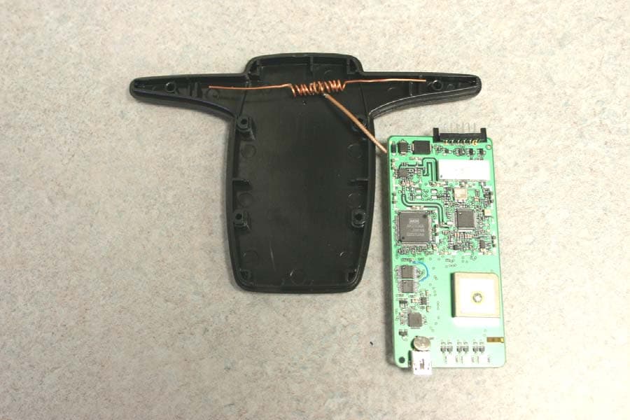
Click to zoom
Application Details
- Equipment Class
- TNB - Licensed Non-Broadcast Station Transmitter
- Date of Grant
- May 01, 2005
- Application Purpose
- Original Equipment
- Date of Application
- May 01, 2005
- Equipment Note
- CYNTRX Tracking Device
- Frequency Range
- 824.01000000 - 848.97000000
- Country
- United States
Documents & Files
Document Text
Text extracted from the exhibit documents filed with the FCC. Open a document above to read the original.
Users Manual
User Guide USB port provides local mapping connectivity to PDA, mobi data terminal or laptop. LED Diagnostics indicate when the unit has successfully locked onto cellular and satellite networks. Minimal Investment. Rapid install with Minimal wiring through ground and 12V constant power. First ever internal antenna GPS vehicle location unit! * * * * * Specifications Indicators: Power Satellite Signal Strength USB Port: USB 1.1 Output: NMEA GPS Receiver: Channels: 16 Accuracy: <4m TTFF: 15s Type ReAcquire: 1 sec. Features Specifications Breakthrough Design Dimensions: 4 x 2.75 x 0.75 inches Weight: 4 oz. Operating Temp: -20 to +60 deg C Power Requirements: Voltage: 11.8 - 13.6 V Curren: Draw at Standby: 110 mA nom 130 mA max Current: Draw at Transmit: 2 Amp Connectors: USB Port Power & Ground Control Cellular Antenna (ext. only) GPS Antenna (ext. only) Installation Guide 1. Locate the fuse panel. Validate which fuses receive constant power. 2. Attach Red/Brown wires to constant power. 3. Attach ground to chassis. Power Ground 12-Volt Battery + - Dc/Dc Adapter CyntrX 4. Validate Power. 5. Using Velcro straps provided: a. Attach CyntrX unit under dash or other covert location, (Model 14000) or b. Run power cable up through dash and attach CyntrX unit to top of dash. (Model 12000 Only) 6. Connecting the Antenna (for Model 14000 only) - Locate a covert location for the antenna, remember no metal materials may be above the antenna, and antenna must be place GPS side towards sky. 7. Move vehicle outside for best GPS coverage. 8. Wait for all 3 lights to turn green. 9. Insert paper clip into reset button (located on bottom of unit) to register unit and turn off lights. Insert paper clip here This document is meant to be guide. If you have any questions during the install please contact your distributor. USB Connector: Provides on board navigation connectivity. LED Diagnostics: LED Diagnotics offer the installer the ability to monitor the status of the unit. During a successful install all lights will be green identifying power is being received by the unit and communications are established. Lights indicate the following (from left to right): Battery, Cellular and GPS. Features Contact Us EVA, Enhanced Vehicle Applications LLC 1901 S. Webster Ave Suite 4 Green Bay, WI 54301 Phone: 920.431.2500 Fax: 920.431.0011 www.evaonline.biz www.cyntrx.com Questions or concerns? For more information log on to our website or contact your local distributor. USB Port LED Diagnostics Document References: N/A Trademark and Copyright Information: Patents, Cyntrx technology is covered by #5,526,401, #5,546,444 U.S. Patents as well as other patents pending. Copyright, this user guide is the property of EVA, Enhanced Vehicle Applications LLC all rights regarding duplication of any content are reserved. Trademarks, Cyntrx™ and On Demand Vehicle Location™ are trademarks of EVA, Enhanced Vehicle Applications LLC. Other, any reference to branded “®, ™, ©” names are the property of their respective owners. FCC/IC Compliance: This device complies with Part 15 of FCC Rules and with RSS-210 of Industry and Science Canada. This device may not cause interference, and this device must accept any interference, including interference that may cause undesired operation of this device. FCC: R4S5150 Canada: SAFETY INFORMATION and FCC Warning - FCC RF Exposure Requirements Exposure To Radio Frequency Signals Your Cyntrx wireless device is a low power radio transmitter and receiver. When installed the device receives and transmits RF signals. In August 1996 the Federal Communications Commission (FCC) adopted RF exposure guidelines with safety levels for mobile wireless devices. Those guidelines are consistent with the safety standards previously set by both U.S. and international standards bodies: American National Standards Institute – ANSI C95.1 (1992) National Council on Radiation Protection and Measurements – NCRP Report 86 (1986) International Commission on Non-Ionizing Radiation Protection – ICNIRP (1996) Those standards were based on comprehensive and periodic evaluations of the relevant scientific literature. For example, over 120 scientists, engineers, and physicians from universities, government’s health agencies, and industry reviewed the available body of research to develop the ANSI Standard (C95.1) WARNING! To comply with FCC RF Exposure compliance requirement, the following antenna installation and device operating configurations must be satisfied: The antenna, used for this transmitter must be installed to provide a separation distance of at least 20 cm from all persons and must not be co-located or operating in conjunction with any other antenna or transmitter. Vehicle antenna mounting: Antenna must be mounted externally to the vehicle. This mounting could be anywhere excepted windows. Safety Tips Your Cyntrx gives you the ability to communicate by data-almost anywhere, anytime. But an important responsibility accompanies the benefits of wireless devices, one that every user/installer must uphold. When installing this device please keep the following items in mind: Get to know your Cyntrx and its features such as voltage, ground, mounting and data connections. The antenna system is 50 ohms. Please use the least amount of distance when installing. We recommend the use of Cyntrx antennas and accessories. Please ask your representative about optional antennas and cables. Position your Cyntrx within RF coverage. Cellular coverage may be poor in basements or tunnels. Install in well-ventilated areas. Excessive heat will damage the Cyntrx or hinder the optimal operation. Electronic Devices Most electronic equipment is shielded from RF signals. However, certain electronic equipment may not be shielded against the RF signals from your Cyntrx. Pacemakers The Health Industry Manufacturers Association recommends that a minimum separation of six (6") inches be maintained between a Cyntrx and a pacemaker to avoid potential interfer…
Text truncated - open the document above for the full version.
Attestation Statements
December 22, 2004 TIMCO Engineering 849 N.W. State Road 45 Newberry, FL 32669 Attn: Mr. Bruno Clavier Reference: EVA Attestation Letter for CyntrX Product Mr. Clavier, The referenced product is designed in compliance with the technical specifications for compatibility of mobile and base stations in the Cellular Radio telephone service contained in “Mobile Station-Land Station Compatibility Specification” as specified in ANSI/TIA/EIA-553-A-1999" The CyntrX product integrates Assisted GPS capability and meets the emergency location requirements of the FCC’s E911 Phase II mandate. Per FCC Part 22.921, when an emergency 911 call is originated by the user, the mobile will attempt to acquire any available system and originate the emergency call on that system, disregarding restrictions set by the roaming list. The FCC NPRM WT99-13, CC94-102 automatic analog A/B roaming option has been implemented for 911 emergency calls. Please note that the EVA CyntrX product has Global Positioning System (GPS) support. Regards, Greg Taisto President EVA
Block Diagram
______________________________________________________________________________________ ______________________________________________________________________________________ R4S5150 Revision: C Confidential & Proprietary Information July 12, 2004 BLOCK DIAGRAMS
External Photos
______________________________________________________________________________________ ______________________________________________________________________________________ R4S5150 Revision: C Confidential & Proprietary Information July 12, 2004 PRODUCT PHOTOS R4S5150I and R4S5150E ______________________________________________________________________________________ ______________________________________________________________________________________ R4S5150 Revision: C Confidential & Proprietary Information July 12, 2004 R4S5150I Showing internal 800MHz antenna assembly ______________________________________________________________________________________ ______________________________________________________________________________________ R4S5150 Revision: C Confidential & Proprietary Information July 12, 2004 R4S5150E Showing external 800MHz and 1.5GHz antenna assemblies
ID Label/Location Info
______________________________________________________________________________________ ______________________________________________________________________________________ R4S5150 Revision: C Confidential & Proprietary Information July 12, 2004 LABEL SAMPLE
Internal Photos
______________________________________________________________________________________ ______________________________________________________________________________________ R4S5150 Revision: C Confidential & Proprietary Information July 12, 2004 PCB Only Top and Bottom
Operational Description
______________________________________________________________________________________ ______________________________________________________________________________________ R4S5150 Revision: C Confidential & Proprietary Information July 12, 2004 CIRCUIT DESCRIPTION Model: 5150I and 5150E (where 5150I and 5150E are internal and external antenna versions of the product) Oscillators’ Frequencies: 14.4Mhz; 1738Mhz – 1788Mhz CPU Operating Frequency: 4.8Mhz Power Input Source: Power supply requirement: +5 volts powered by an External 12 to 5 VDC-DC converter Antenna 5150E Frequency range: 824Mhz – 894Mhz In/out impedance: 50 ohms – unbalanced Gain: +0.8dBi (peak); -2.6dBi (average) Antenna 5150I PCB mounted GPS 1574Mhz patch LNA and matching circuit PCB mounted 824 – 894MHz Transmitter Transmit frequencies – 824.1Mhz to 849 Mhz Maximum RF output power is 1200mW Channel spacing: 30Khz 20dB bandwidth: 19Khz Oscillator frequencies: 824Mhz – 849Mhz
Parts List/Tune Up Info
EVA - Enhanced Vehicle Applications, LLC CyntrX BOM Released For Production - MDH 10/11/04 Item Class Mfg.Part Number Mfg. Qty * Qty ** Description Circuit Reference Alternate Mfg. Alt. Mfg Part # Comments 1 Resistor MCR01MZSJ102 Rohm 7 7 1K Ohm, +/-5%, 0402 R1,R32,R62,R115,R116,R125, R129 KOA 2 Resistor MCR01MZSJ302 Rohm 1 1 3K Ohm, +/-5%, 0402 R2 KOA 3 Resistor MCR01MZSJ562 Rohm 1 1 5.6K Ohm, +/-5%, 0402 R3 KOA 4 Resistor MCR01MZSJ105 Rohm 2 2 1M Ohm, +/-5%, 0402 R4, R57 KOA 5 Resistor MCR01MZSJ474 Rohm 1 1 470K Ohm, +/-5%, 0402 R246 KOA 6 Resistor MCR01MZSJ472 Rohm 4 4 4.7K Ohm, +/-5%, 0402 R6,R103,R247,R252 KOA 7 Resistor MCR01MZSJ204 Rohm 1 1 200K Ohm, +/-5%, 0402 R5 8 Resistor MCR01MZSJ153 Rohm 2 2 150K, +/- 5%, 0402 R7,R143 KOA 9 Resistor MCR01MZSJ104 Rohm 12 12 100K Ohm, +/-5%, 0402 R8,R17,R20,R42,R46,R49, R56,R128,R144,R153,R248, R263 KOA Removed R57 10 Resistor MCR01MZSF1211 Rohm 2 2 1.21K Ohm, +/-1%, 0402 R9,R11 KOA Observe 1% Tolerance 11 Resistor MCR01MZSF3321 Rohm 2 2 3.32K Ohm, +/-1%, 0402 R10,R12 KOA Observe 1% Tolerance 12 Resistor MCR01MZSJ180 Rohm 1 1 18 Ohm, +/-5%, 0402 R13 KOA 13 Resistor MCR01MZSJ000 Rohm 4 5 0 Ohm, +/-5%, 0402 R14,R21,R28,R30,R59 KOA Pop R59 For External GPS Antenna 14 Resistor MCR01MZSJ100 Rohm 2 2 10 Ohm, +/-5%, 0402 R18,R111 KOA 15 Resistor MCR01MZSJ513 Rohm 1 1 51K Ohm, +/-5%, 0402 R24 KOA 16 Resistor MCR01MZSJ471 Rohm 2 2 470 Ohm, +/-5%, 0402 R25,R210 KOA 17 Resistor MCR01MZSJ123 Rohm 2 2 12K Ohm, +/-5%, 0402 R27,R207 KOA 18 Resistor MCR01MZSJ150 Rohm 2 2 150 Ohm, +/-5%, 0402 R33, R58 19 Resistor MCR01MZSJ222 Rohm 7 7 2.2K Ohm, +/-5%, 0402 R35,R37,R38,R40,R41,R104,R105 KOA 20 Resistor MCR01MZSJ680 Rohm 4 4 68 Ohm, +/-5%, 0402 R36,R39,R102,R209 KOA 21 Resistor MCR01MZSJ103 Rohm 11 11 10K Ohm, +/-5%, 0402 R23,R43,R44,R47,R50,R51,R54,R63,R132,R253,R254 KOA Removed R34, R48, and R133 22 Resistor MCR01MZSF1303 Rohm 1 1 130K Ohm, +/-1%, 0402 R45 KOA Observe 1% Tolerance 23 Resistor MCR01MZSJ202 Rohm 1 1 2K Ohm, +/-5%, 0402 R52 KOA 24 Resistor MCR01MZSJ201 Rohm 1 1 200 Ohm, +/-5%, 0402 R53 KOA 25 Resistor MCR01MZSJ360 Rohm 1 1 36 Ohm, +/-5%, 0402 R55 KOA 26 Resistor MCR01MZSJ564 Rohm 2 2 560K Ohm, +/-5%, 0402 R126,R131 KOA 27 Resistor MCR01MZSJ623 Rohm 1 1 62K Ohm, +/-5%, 0402 R136 KOA 28 Resistor MCR01MZSJ150 Rohm 1 1 15 Ohm, +/-5%, 0402 R138 KOA 29 Resistor MCR01MZSJ101 Rohm 6 6 100 Ohm, +/-5%, 0402 R22,R34,R60,R61,R201,R260 KOA Added R34 30 Resistor MCR01MZSJ223 Rohm 2 2 22K Ohm, +/-5%, 0402 R64,R206 KOA Added R64, Removed R217 31 Resistor MCR01MZSJ620 Rohm 1 1 62 Ohm, +/-5%, 0402 R245 KOA 32 Resistor MCR01MZSJ510 Rohm 1 1 51 Ohm, +/-5%, 0402 R255 KOA 33 Capacitor MCH155AN4R7C Rohm 2 2 4.7pF_0402_NPO_50V C1,C4 34 Capacitor MCH155AN150J Rohm 1 1 15pF_0402_NPO_50V C2 35 Capacitor Rohm 0 0 T.B.D. 0603_NPO_50V C3 KOA 36 Capacitor MCH153FN104ZK Rohm 21 20 100nF_0402_X7R_16V C5,C24,C28,C47,C55,C56, C59,C63,C64,C69,C74,C76,C114,C118,C129,C131,C136,C137,C204,C259,C278 KOA No-Pop C55 For External GPS Antenna 37 Capacitor MCH153CN223K Rohm 5 5 22nF_0402_X7R_50V C6,C12,C13,C25,C73 38 Capacitor MCH155CN102KK Rohm 14 14 1nF_0402_X7R_50V C7,C22,C23,C39,C40,C50,C58,C60,C253,C261,C265,C266,C268,C276 KOA Added C266 39 Capacitor MCH155A101JK Rohm 13 12 100pF_0402_NP0_50V C8,C10,C17,C21,C35,C49,C52,C71,C75,C77,C140,C251,C260 KOA No-Pop C75 For External GPS Antenna 40 Capacitor MCH184CN334K Rohm 2 2 330nF_0603_X5R_10V C11,C14 KOA Removed C27 41 Capacitor JMK105BJ334KV-F Taiyo Yuden 1 1 330nF_0402_X5R_10V C27 42 Capacitor JMK105BJ105KV-F Taiyo Yuden 16 16 1.0uF_0402_X5R_6.3V C15,C16,C18,C19,C62,C65, C66,C120,C121,C123,C124, C126,C127,C135,C206,C211 Murata GRM155R60J105KE19D Added C15, C16 43 Capacitor MCH214CN225KP Rohm 4 4 2.2uF_0805_X7R__10V C20,C67,C128,C130 KOA 44 Capacitor MCH155AN181J Rohm 1 1 180pF_0402_NPO_50V C26 45 Capacitor MCH153CN103KK Rohm 3 2 10nF_0402_X7R_16V C29,C68,C70 KOA No-Pop C70 For External GPS Antenna 46 Capacitor MCH155CN472K Rohm 2 2 4.7nF_0402_X7R_50V C30,C32 47 Capacitor C0402X7R160-123KNP Venkel 2 2 12nF_0402_X7R_16V C31,C33 KOA 48 Capacitor HPC0402A1R5AXXT1 Vishay 1 1 1.5pF_0402_NPO_25V_+/-0.05pF C43 49 Capacitor MCH155CN332KK Rohm 1 1 3.3nF_0402_X7R_50V C46 KOA 50 Capacitor TCFGP0J106M8R (P case) Rohm 2 2 10uF_0805 Tant._6.3V C51,C203 KOA 51 Capacitor TCFGA0J226M8R (A case) Rohm 1 1 22uF_1206 Tant._6.3V C53 KOA 52 Capacitor MCH155CN470JK Rohm 3 0 47pF_0402_NPO_50V C54,C57,C61 KOA No-Pop C54, C57, C61 For Ext. GPS Antenna 53 Capacitor MCH183AN027 Rohm 1 0 TBD_0603_NPO_50V C72 KOA No-Pop C72 For External GPS Antenna 54 Capacitor MCH214CN475KP Rohm 3 3 4.7uF_0805_X5R_10V C105,C106,C107 KOA 55 Capacitor MCH155A220JK Rohm 1 1 22pF_0402_NP0_50V C117 KOA 56 Capacitor MCH153CN473K Rohm 2 2 47nF_0402_X7R__16V C125,C132 KOA 1 Confidential / Proprietary 10/12/2004 9:59 AM EVA - Enhanced Vehicle Applications, LLC CyntrX BOM Released For Production - MDH 10/11/04 Item Class Mfg.Part Number Mfg. Qty * Qty ** Description Circuit Reference Alternate Mfg. Alt. Mfg Part # Comments 57 Capacitor MCH155CN330JK Rohm 6 6 33pF_0402_NP0_50V C205,C207,C252,C258,C264,C275 KOA 58 Capacitor MCH155A050CK Rohm 1 1 5pF_0402_NP0_50V C215 KOA 59 Capacitor MCH155A040CK Rohm 1 1 4pF_0402_NP0_50V C262 KOA 60 Capacitor MCH155A080DK Rohm 3 3 8pF_0402_NP0_50V C263,C277,C289 KOA 61 Inductor 0402CS-3N9XGBW Coilcraft 2 1 3.9nH, Wirewound Inductor_0402, 2% L1, L10 IGS F0402CT3N9B No-Pop L10 For External GPS Antenna 62 Inductor 0402CS-XNXXJW Coilcraft 1 1 TBD, Wirewound Inductor_0402, 5% L2 IGS 63 Inductor 0402CS-2N4XJW Coilcraft 1 0 2.2nH Inductor_0402_+/-5% L4 IGS No-Pop L4 For External GPS Antenna 64 Inductor 0402CS-68XKBW Coilcraft 1 1 68nH, Wirewound Inductor_0402, 10% L5 IGS FN0402CT68NK 65 Inductor HK1005470J-T Taiyo Yuden 3 2 47nH Inductor_0402_+/-5% L3,L6,L9 No-Pop L9 For External GPS Antenna 66 Inductor 0402CS-2N0XGBW Coilcraft 2 2 2.0nH, Wirewound Inductor_0402_+/-2% L7, L8 IGS FN0402CT2N0S 67 Inductor Coilcraft 1 0 T.B.D.,Wirewound Inductor_0402_+/-5% L11 No-Pop L11 Fo…
Text truncated - open the document above for the full version.
Parts List/Tune Up Info
______________________________________________________________________________________ ______________________________________________________________________________________ R4S5150 Revision: C Confidential & Proprietary Information July 12, 2004 TUNING PROCEDURES SETUP Connect the EUT to an HP8920B using the AUDIO JACK and RF to SMA cables supplied. Connect AFI to the HP8920 AUDIO IN. Connect AFO to the HP8920 AUDIO OUT. Connect the RF cable to the HP8920 RF IN. Using the ALIGNMENT.EXE software adjust the EUT to the following specs. TEST ITEMCOMMAND MEASUREMENT LEVELFILTERDEVIATIONFREQ OUTPUTTARGETMINMAX (dBm)(KHz)(KHz)(KHz)(mV) Descri ption Protocol Direction 1TCXO FrequencyUSE PC TOOL OFF0.30015XXFREQ848,970,000848,970,424848,969,576 2Demodulation LevelUSE PC TOOL -500.30015XXAFI (H)101 dbuv98 dbuv102 dbuv 3Power Level 0 – Low FrequencyUSE PC TOOL OFF0.30015XXPOWER29 dbm27 dbm33 dbm Power Level 1 – Low FrequencyUSE PC TOOL OFF0.30015XXPOWER28 dbm27 dbm33 dbm Power Level 2 – Low FrequencyUSE PC TOOL OFF0.30015XXPOWER27 dbm27 dbm33 dbm 4Power Level 3 – Low FrequencyUSE PC TOOL OFF0.30015XXPOWER23 dbm21 dbm25 dbm 5Power Level 4 – Low FrequencyUSE PC TOOL OFF0.30015XXPOWER19 dbm17 dbm21 dbm 6Power Level 5 – Low FrequencyUSE PC TOOL OFF0.30015XXPOWER15 dbm12 dbm17 dbm 7Power Level 6 – Low FrequencyUSE PC TOOL OFF0.30015XXPOWER11 dbm8 dbm13 dbm 8Power Level 7 – Low FrequencyUSE PC TOOL OFF0.30015XXPOWER7 dbm5 dbm9 dbm 9Power Level 0 – Mid FrequencyUSE PC TOOL OFF0.30015XXPOWER29 dbm27 dbm33 dbm Power Level 1 – Mid FrequencyUSE PC TOOL OFF0.30015XXPOWER28 dbm27 dbm33 dbm Power Level 2 – Mid FrequencyUSE PC TOOL OFF0.30015XXPOWER27 dbm27 dbm33 dbm 10Power Level 3 – Mid FrequencyUSE PC TOOL OFF0.30015XXPOWER23 dbm21 dbm25 dbm 11Power Level 4 – Mid FrequencyUSE PC TOOL OFF0.30015XXPOWER19 dbm17 dbm21 dbm 12Power Level 5 – Mid FrequencyUSE PC TOOL OFF0.30015XXPOWER15 dbm12 dbm17 dbm 13Power Level 6 – Mid FrequencyUSE PC TOOL OFF0.30015XXPOWER11 dbm8 dbm13 dbm 14Power Level 7 – Mid FrequencyUSE PC TOOL OFF0.30015XXPOWER7 dbm5 dbm9 dbm 15Power Level 0 – High FrequencyUSE PC TOOL OFF0.30015XXPOWER29 dbm27 dbm33 dbm Power Level 1 – High FrequencyUSE PC TOOL OFF0.30015XXPOWER28 dbm27 dbm33 dbm Power Level 2 – High FrequencyUSE PC TOOL OFF0.30015XXPOWER27 dbm27 dbm33 dbm 16Power Level 3 – High FrequencyUSE PC TOOL OFF0.30015XXPOWER23 dbm21 dbm25 dbm 17Power Level 4 – High FrequencyUSE PC TOOL OFF0.30015XXPOWER19 dbm17 dbm21 dbm 18Power Level 5 – High FrequencyUSE PC TOOL OFF0.30015XXPOWER15 dbm12 dbm17 dbm 19Power Level 6 – High FrequencyUSE PC TOOL OFF0.30015XXPOWER11 dbm8 dbm13 dbm 20Power Level 7 – High FrequencyUSE PC TOOL OFF0.30015XXPOWER7 dbm5 dbm9 dbm 21Wide band Modulation Deviation – Low FrequencyUSE PC TOOL OFF0.3001513,000DEVIATION13 khz12.5 khz13.5 khz 22Wide band Modulation Deviation – Mid FrequencyUSE PC TOOL OFF0.3001513,000DEVIATION13 khz12.5 khz13.5 khz 23Wide band Modulation Deviation – High FrequencyUSE PC TOOL OFF0.3001513,000DEVIATION13 khz12.5 khz13.5 khz 24ST Level – Low FrequencyUSE PC TOOL OFF0.30015XXDEVIATION8 khz7.5 khz8.5 khz 25ST Level – Mid FrequencyUSE PC TOOL OFF0.30015XXDEVIATION8 khz7.5 khz8.5 khz 26ST Level – High FrequencyUSE PC TOOL OFF0.30015XXDEVIATION8 khz7.5 khz8.5 khz 27SAT Level – Low FrequencyUSE PC TOOL OFF<.0206XXDEVIATION2 khz1.9 khz2.2 khz 28SAT Level – Mid FrequencyUSE PC TOOL OFF<.0206XXDEVIATION2 khz1.9 khz2.2 khz 29SAT Level – High FrequencyUSE PC TOOL OFF<.0206XXDEVIATION2 khz1.9 khz2.2 khz 30MICIN Deviation – Low FrequencyUSE PC TOOL OFFC Mess99150DEVIATION2.9 khz2.5 khx3.3 khx 31MICIN Deviation – Mid FrequencyUSE PC TOOL OFFC Mess99150DEVIATION2.9 khz2.5 khx3.3 khx 32MICIN Deviation – High FrequencyUSE PC TOOL OFFC Mess99150DEVIATION2.9 khz2.5 khx3.3 khx 33Tone In Deviation – Low FrequencyUSE PC TOOL OFF0.3003XXDEVIATION8.6 khz8 khz9 khz 34Tone In Deviation – Mid FrequencyUSE PC TOOL OFF0.3003XXDEVIATION8.6 khz8 khz9 khz 35Tone In Deviation – High FrequencyUSE PC TOOL OFF0.3003XXDEVIATION8.6 khz8 khz9 khz 36Compressor LinearityUSE PC TOOL 37Expander LenearityUSE PC TOOL 38 -110 dBm input level captureUSE PC TOOL -100XXXXNANANA 39 -100 dBm input level captureUSE PC TOOL -90XXXXNANANA 40 -90 dBm input level captureUSE PC TOOL -80XXXXNANANA DON'T ADJUST DON'T ADJUST HP8920 SPECIFICATION RX RF GENERATORAFO
Schematics
CyntrX_INFINEON_revD.sch-1 - Thu Aug 19 12:33:00 2004 CyntrX_INFINEON_revD.sch-2 - Thu Aug 19 12:33:02 2004
Test Report
TIMCO ENGINEERING INC. 849 NW State Road 45 Newberry, Florida 32669 http://www.timcoengr.com 888.472.2424 F 352.472.2030 email: [email protected] APPLICANT: EVA, LLC. FCC ID: R4S5150 REPORT #: E\EVA_\1319ZUT4\1319ZUT4TestReport.doc COVER SHEET Test Report Product Name: CYNTRX VEHICLE TRACKING DEVICE W/EXTERNAL GPS ATTATCHED ANTENNA FCC ID: R4S5150 Applicant: EVA, LLC. 1901 S WEBSTER AVE., SUITE 4 GREEN WAY WI 54301 Date Receipt: OCTOBER 4, 2004 Date Tested: OCTOBER 15, 2004 TIMCO ENGINEERING INC. 849 NW State Road 45 Newberry, Florida 32669 http://www.timcoengr.com 888.472.2424 F 352.472.2030 email: [email protected] APPLICANT: EVA, LLC. FCC ID: R4S5150 REPORT #: E\EVA_\1319ZUT4\1319ZUT4TestReport.doc TABLE OF CONTENTS APPLICANT: EVA, LLC. FCC ID: R4S5150 TABLE OF CONTENTS TEST REPORT: PAGE 1........GENERAL DESCRIPTION & TECHNICAL DESCRIPTION PAGE 2........TECHNICAL DESCRIPTION CONTINUED PAGE 3........RF OUTPUT POWER PAGE 4........OCCUPIED BANDWIDTH PAGE 5-9......OCCUPIED BANDWIDTH PLOTS PAGE 10.......SPURIOUS EMISSION AT ANTENNA TERMINALS METHOD OF MEASURING SPURIOUS EMISSIONS AT ANTENNA TERMINALS PAGE 11-12....FIELD STRENGTH OF SPURIOUS EMISSIONS PAGE 13.......METHOD OF MESURING RADIATED SPURIOUS EMISSIONS PAGE 14.......FREQUENCY STABILITY PAGE 15-20....EQUIPMENT LIST EXHIBITS INCLUDING: BLOCK DIAGRAM SCHEMATIC PARTS LIST USERS MANUAL LABEL SAMPLE LABEL LOCATION EXTERNAL PHOTOGRAPHS INTERNAL PHOTOGRAPHS ALIGNMENT PROCEDURE OPERATIONAL DESCRIPTION TEST SET UP PHOTOGRAPHS TIMCO ENGINEERING INC. 849 NW State Road 45 Newberry, Florida 32669 http://www.timcoengr.com 888.472.2424 F 352.472.2030 email: [email protected] APPLICANT: EVA, LLC. FCC ID: R4S5150 REPORT #: E\EVA_\1319ZUT4\1319ZUT4TestReport.doc Page 1 of 20 GENERAL INFORMATION 2.1033(c)(1)(2) EVA, LLC. will sell the FCC ID: R4S5150, Fixed WLL cellular phone for use under FCC RULES PART 22(H) . 2.1033(c) TECHNICAL DESCRIPTION 2.1033 (3) The User Manual is included in the exhibits. 2.1033 (4) Type of Emission: Emission Designator = 40K0F8W Calculation: Voice + SAT Modulation: Voice is 2.5 kHz and SAT is 6 kHz Maximum modulation is M = 6 kHz Deviation: Voice is 12 kHz and SAT is 2 kHz Maximum deviation is D = 12 + 2 = 14 kHz Bn = 2xM + 2xDK with K = 1 Bn = 40 kHz Calculation: Signaling Tone (ST) + SAT Modulation: ST is 10 kHz and SAT is 6 kHz Maximum modulation is M = 10 kHz Deviation: ST is 8 kHz and SAT is 2 kHz Maximum deviation is D = 8 + 2 = 10 kHz Bn = 2xM + 2xDK with K = 1 Bn = 40 kHz Emission Designator = 40K0F1D Calculation: Voice + SAT Modulation: Wideband Data is 10 kHz and SAT is 6 kHz Maximum modulation is M = 10 kHz Deviation: Wideband Data is 8 kHz and SAT is 2 kHz Maximum deviation is D = 8 + 2 = 10 kHz Bn = 2xM + 2xDK with K = 1 Bn = 40 kHz TIMCO ENGINEERING INC. 849 NW State Road 45 Newberry, Florida 32669 http://www.timcoengr.com 888.472.2424 F 352.472.2030 email: [email protected] APPLICANT: EVA, LLC. FCC ID: R4S5150 REPORT #: E\EVA_\1319ZUT4\1319ZUT4TestReport.doc Page 2 of 20 2.1033 (5) Frequency Range: 824-849 MHz (6) Power Range and Controls: There are NO user Power controls. (7) Maximum Output Power Rating: 0.25 Watts ERP (8) DC Voltages and Current into Final Amplifier: POWER INPUT FINAL AMPLIFIER ONLY Vce =5.0 Volts IC = 1.3 A Pin = 6.5 W (9) Tune-up procedure. The tune-up procedure is given in the exhibits (10) Complete Circuit Diagrams: Description of all circuitry and devices provided for determining and stabilizing frequency is included in the circuit description in the instruction manual. The circuit diagram and block diagram are included in the exhibits. 2.1033(c)(11) A photograph or drawing of the equipment identification label is shown in the Exhibits. 2.1033(c)(12) Photographs of the equipment of sufficient clarity to reveal equipment construction and layout and label location, are shown in the Exhibits. 2.1033(c)(13) For equipment employing digital modulation, a detail description of the modulation technique. This UUT uses analogue FM to modulate the transmitter. 2.1033(c)(14) Data required for 2.1046 to 2.1057 See Below TIMCO ENGINEERING INC. 849 NW State Road 45 Newberry, Florida 32669 http://www.timcoengr.com 888.472.2424 F 352.472.2030 email: [email protected] APPLICANT: EVA, LLC. FCC ID: R4S5150 REPORT #: E\EVA_\1319ZUT4\1319ZUT4TestReport.doc Page 3 of 20 22.913 Power Output – Effective Radiated Power - ERP Method of measurement: This test was performed per TIA/EIA STANDARD 603 using the substitution method. Tuned Frequency (MHz) Polarization (H/V) ERP (dBm) ERP (W) 824.7 V 24.0 0.251 835.8 V 23.5 0.224 848.0 V 23.5 0.224 2.1047(a) Voice Modulation characteristics: NOT APPLICABLE, F8 type of emission. 2.1047 Audio Low Pass Filter This UUT does not have a low pass filter. TIMCO ENGINEERING INC. 849 NW State Road 45 Newberry, Florida 32669 http://www.timcoengr.com 888.472.2424 F 352.472.2030 email: [email protected] APPLICANT: EVA, LLC. FCC ID: R4S5150 REPORT #: E\EVA_\1319ZUT4\1319ZUT4TestReport.doc Page 4 of 20 2.1049 Occupied bandwidth: 99% power bandwidth: 22.917 (a) Out of band emissions : The mean power of emissions must be attenuated below the mean power of the un-modulated carrier (P) on any frequency twice or more than twice the fundamental frequency by: At least 43 + 10log(Po) = dB. Band-edges compliance: Measurement were performed in accordance with Part 22.917 Output Power: 24 dBm Channel (MHz) Band-edge Frequency (MHz) Amplitude level at the band-edge(dBm) Limit (dBm) Margin (dB) 824.7 824.0 -14.7 -13.0 -1.7 848.0 849.0 -15.6 -13.0 -2.6 The following plot shows the composite power measured with a RBW = 3MHz = VBW and the modulated envelop measured with a RBW = 30 kHz = VBW TIMCO ENGINEERING INC. 849 NW State Road 45 Newberry, Florida 32669 http://www.timcoengr.com 888.472.2424 F 352.472.2030 email: [email protected] APPLICANT: EVA, LLC. FCC ID: R4S5150 REPORT #: E\EVA_\1319ZUT4\1319ZUT4TestReport.doc Page 5 of 20 OCCUPIED BANDWIDTH TIMCO ENGINEERING INC. 849 NW State Road 45 Newberr…
Text truncated - open the document above for the full version.
Contact Information
Applicant
Greg Taisto(President)
Test Firm
Timco Engineering, Inc.S Sanders
Technical Specifications
| # | Rule Parts | Frequency Range | Power Output | Emission | Tolerance |
|---|---|---|---|---|---|
| 2 | 22H | 824.01 MHz - 848.97 MHz | 250.00 mW | 40K0F8W | 2.5 ppm |