R6PT503FGSM 900/1800/1900 Mobile Phone
Beaucom Co,. Ltd.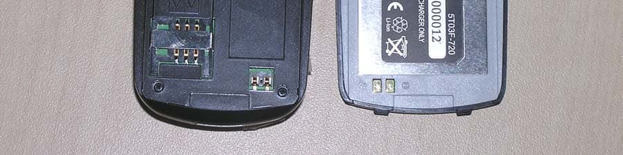
Click to zoom
Application Details
- Equipment Class
- PCE - PCS Licensed Transmitter held to ear
- Date of Grant
- Dec 15, 2004
- Application Purpose
- Original Equipment
- Date of Application
- Dec 15, 2004
- Equipment Note
- GSM 900/1800/1900 Mobile Phone
- Frequency Range
- 1850.20000000 - 1909.80000000
- Company
- Beaucom Co,. Ltd.
- Country
- South Korea
Documents & Files
Document Text
Text extracted from the exhibit documents filed with the FCC. Open a document above to read the original.
Users Manual
Engineering T503F Rev 1.04 2004-12-10 1 of 77 T503F User Manual GSM/GPRS Engineering T503F Rev 1.04 2004-12-10 2 of 77 Overview of keys Volume Up/Down Call key Activate menu or cancel a selection PoC Delete or backspace Microphone Scroll up/down on a menu. Move left/right on an edit field Power On/Off or Cancel Ear-mic Jack Earpiece Active or cancel submenu Camera Display screen punctuation key Antenna LED Secondary Display : Caller-ID & Time display Charger connector & Data Buzzer/Ringer RF Connector Engineering T503F Rev 1.04 2004-12-10 3 of 77 Overview of Display Signal strength indicator. Alarm mode indicator. Roam indicator. Text message (SMS) indicator. Missed call indicator Keyboard locked indicator Silent ring indicator Call Forwarding indicator GPRS indicator. Vibrator on indicator. Battery power level Engineering T503F Rev 1.04 2004-12-10 4 of 77 Contents Overview of keys............................................................................................................................................................................. 2 Overview of Display ........................................................................................................................................................................ 3 Contents.......................................................................................................................................................................................... 4 Introduction ..................................................................................................................................................................................... 5 Security ........................................................................................................................................................................................... 5 Safety and General Information ...................................................................................................................................................... 5 Personal.............................................................................................................................................................................................................................................................................................5 Mobile phone Use.....................................................................................................................................................................................................................................................................6 B a t t e r y U s e ......................................................................................................................................................................................................................................................................................7 O n t h e R o a d ...................................................................................................................................................................................................................................................................................7 I n s i d e A i r c r a f t .................................................................................................................................................................................................................................................................................7 Getting Started ................................................................................................................................................................................ 8 B a t t e r y ..................................................................................................................................................................................................................................................................................................9 S w i t c h i n g O N a n d O F F & P I N e n t r y ...................................................................................................................................................................................................................... 10 Making phone calls ....................................................................................................................................................................... 11 M a k i n g c a l l s ................................................................................................................................................................................................................................................................................. 12 A n s w e r i n g C a l l s ....................................................................................................................................................................................................................................................................... 13 M i s s e d & R e j e c t e d C a l l s .................................................................................................................................................................................................................................................. 14 A c t i v e C a l l ...................................................................................................................................................................................................................................................................................... 15 I n C a l l F e a t u r e s ........................................................................................................................................................................................................................................................................ 16 The Menu Structure ................................…
Text truncated - open the document above for the full version.
External Photos
EUT – Top view EUT - Bottom view
ID Label/Location Info
Doc. Type Author Page of Pages Product Specification ST Lin GSM 1 of 2 Concerning Doc. No. Rev. Date T503F –GPRS Tri Band GSM - 0.004-11-22 Label Sheet -Phone A IMEI label goes on bottom of the phone Doc. Type Author Page of Pages Product Specification ST Lin GSM 2 of 2 Concerning Doc. No. Rev.Date T503F –GPRS Tri Band GSM - 0.004-11-22 Tresor Data Ltd. Company confidential, GSM team Internal Use Only. -Battery A battery label goes on bottom of the battery
Internal Photos
PCB – Top view PCB - Bottom view
RF Exposure Info
SAR Test Report No.: SAR_713_2004_FCC_1900 Date of Report: 09/17/2004 Appendix A Plots Page 1 of 9 System / software: SARA2 / 2.3 VPM Input Power Drift: Date / Time: 8/25/2004 11:14:06 AM DUT Battery Model/No: Filename: lefttch885_3d.txt Probe Serial Number: 0106 Ambient Temperature: 22.0°C Liquid Simulant: 1900 Device Under Test: Tresor T503f Relative Permittivity: 39.42 Relative Humidity: 50% Conductivity: 1.433 Phantom S/No: HeadFT26.csv Liquid Temperature: 22.0°C Phantom Rotation: 0° Max SAR Y-axis Location: -53.00 mm DUT Position: left touch Max SAR Z-axis Location: -173.20 mm Antenna Configuration: Integral Max E Field: 23.92 V/m Test Frequency: 1880MHz SAR 1g: 0.772 W/kg Air Factors: 415 / 805 / 371 SAR 10g: 0.439 W/kg Conversion Factors: 0.423 / 0.423 / 0.423 SAR Start: 0.293 W/kg Type of Modulation: SAR End: 0.294 W/kg Modn. Duty Cycle: SAR Drift during Scan: 0.02 dB Diode Compression Factors (V*200): 9.4 / 2.7 / 7.8 Probe battery last changed: 7/22/2004 Input Power Level: max Extrapolation: poly4 SAR Test Report No.: SAR_713_2004_FCC_1900 Date of Report: 09/17/2004 Appendix A Plots Page 2 of 9 System / software: SARA2 / 2.3 VPM Input Power Drift: Date / Time: 8/25/2004 11:44:05 AM DUT Battery Model/No: Filename: lefttch661_3d.txt Probe Serial Number: 0106 Ambient Temperature: 22.0°C Liquid Simulant: 1900 Device Under Test: Tresor T503f Relative Permittivity: 39.42 Relative Humidity: 50% Conductivity: 1.433 Phantom S/No: HeadFT26.csv Liquid Temperature: 22.0°C Phantom Rotation: 0° Max SAR Y-axis Location: -13.00 mm DUT Position: left tilt Max SAR Z-axis Location: -131.60 mm Antenna Configuration: Integral Max E Field: 10.90 V/m Test Frequency: 1880MHz SAR 1g: 0.148 W/kg Air Factors: 415 / 805 / 371 SAR 10g: 0.088 W/kg Conversion Factors: 0.423 / 0.423 / 0.423 SAR Start: 0.052 W/kg Type of Modulation: SAR End: 0.052 W/kg Modn. Duty Cycle: SAR Drift during Scan: -0.02 dB Diode Compression Factors (V*200): 9.4 / 2.7 / 7.8 Probe battery last changed: 7/22/2004 Input Power Level: max Extrapolation: poly4 SAR Test Report No.: SAR_713_2004_FCC_1900 Date of Report: 09/17/2004 Appendix A Plots Page 3 of 9 System / software: SARA2 / 2.3 VPM Input Power Drift: Date / Time: 8/25/2004 12:15:55 PM DUT Battery Model/No: Filename: lefttlt661_3d.txt Probe Serial Number: 0106 Ambient Temperature: 22.0°C Liquid Simulant: 1900 Device Under Test: Tresor T503f Relative Permittivity: 39.42 Relative Humidity: 50% Conductivity: 1.433 Phantom S/No: HeadFT26.csv Liquid Temperature: 22.0°C Phantom Rotation: 180° Max SAR Y-axis Location: 65.00 mm DUT Position: right touch Max SAR Z-axis Location: -156.40 mm Antenna Configuration: Integral Max E Field: 18.25 V/m Test Frequency: 1880MHz SAR 1g: 0.438 W/kg Air Factors: 415 / 805 / 371 SAR 10g: 0.273 W/kg Conversion Factors: 0.423 / 0.423 / 0.423 SAR Start: 0.150 W/kg Type of Modulation: SAR End: 0.151 W/kg Modn. Duty Cycle: SAR Drift during Scan: 0.02 dB Diode Compression Factors (V*200): 9.4 / 2.7 / 7.8 Probe battery last changed: 7/22/2004 Input Power Level: max Extrapolation: poly4 SAR Test Report No.: SAR_713_2004_FCC_1900 Date of Report: 09/17/2004 Appendix A Plots Page 4 of 9 System / software: SARA2 / 2.3 VPM Input Power Drift: Date / Time: 8/26/2004 4:23:39 PM DUT Battery Model/No: Filename: temp.txt Probe Serial Number: 0106 Ambient Temperature: 22.0°C Liquid Simulant: 1900 Device Under Test: Tresor T503f Relative Permittivity: 39.42 Relative Humidity: 50% Conductivity: 1.433 Phantom S/No: HeadFT26.csv Liquid Temperature: 22.0°C Phantom Rotation: 180° Max SAR Y-axis Location: 13.00 mm DUT Position: right tilt Max SAR Z-axis Location: -129.20 mm Antenna Configuration: Integral Max E Field: 10.23 V/m Test Frequency: 1880MHz SAR 1g: 0.123 W/kg Air Factors: 415 / 805 / 371 SAR 10g: 0.073 W/kg Conversion Factors: 0.423 / 0.423 / 0.423 SAR Start: 0.047 W/kg Type of Modulation: SAR End: 0.046 W/kg Modn. Duty Cycle: SAR Drift during Scan: -0.06 dB Diode Compression Factors (V*200): 9.4 / 2.7 / 7.8 Probe battery last changed: 7/22/2004 Input Power Level: max Extrapolation: poly4 SAR Test Report No.: SAR_713_2004_FCC_1900 Date of Report: 09/17/2004 Appendix A Plots Page 5 of 9 System / software: SARA2 / 2.3 VPM Input Power Drift: Date / Time: 8/26/2004 4:55:25 PM DUT Battery Model/No: Filename: righttlt661_3d.txt Probe Serial Number: 0106 Ambient Temperature: 22.0°C Liquid Simulant: 1900 Device Under Test: Tresor T503f Relative Permittivity: 39.68 Relative Humidity: 50% Conductivity: 1.413 Phantom S/No: HeadFT26.csv Liquid Temperature: 22.0°C Phantom Rotation: 0° Max SAR Y-axis Location: -50.00 mm DUT Position: left touch Max SAR Z-axis Location: -175.60 mm Antenna Configuration: Integral Max E Field: 22.43 V/m Test Frequency: 1850.2MHz SAR 1g: 0.642 W/kg Air Factors: 415 / 805 / 371 SAR 10g: 0.389 W/kg Conversion Factors: 0.423 / 0.423 / 0.423 SAR Start: 0.259 W/kg Type of Modulation: SAR End: 0.258 W/kg Modn. Duty Cycle: SAR Drift during Scan: -0.02 dB Diode Compression Factors (V*200): 9.4 / 2.7 / 7.8 Probe battery last changed: 7/22/2004 Input Power Level: max Extrapolation: poly4 SAR Test Report No.: SAR_713_2004_FCC_1900 Date of Report: 09/17/2004 Appendix A Plots Page 6 of 9 System / software: SARA2 / 2.3 VPM Input Power Drift: Date / Time: 8/26/2004 5:24:27 PM DUT Battery Model/No: Filename: lefttch512_3d.txt Probe Serial Number: 0106 Ambient Temperature: 22.0°C Liquid Simulant: 1900 Device Under Test: Tresor T503f Relative Permittivity: 39.18 Relative Humidity: 50% Conductivity: 1.462 Phantom S/No: HeadFT26.csv Liquid Temperature: 22.0°C Phantom Rotation: 0° Max SAR Y-axis Location: -50.00 mm DUT Position: left touch Max SAR Z-axis Location: -175.60 mm Antenna Configuration: Integral Max E Field: 28.11 V/m Test Frequency: 1909.8MHz SAR 1g: 1.047 W/kg Air Factors: 415 / 805 / 371 SAR 10g: 0.623 W/kg Conversion Factors: 0.423 / 0.423 / 0.423 SAR Start: 0.402 W/kg Type of Modulation: SAR End: 0.406 W/kg Modn. Duty Cycle: SAR Drift during Scan: 0.04 dB Dio…
Text truncated - open the document above for the full version.
RF Exposure Info
SAR Test Report No. SAR_713_2004_FCC_1900 Date of Report: 09/17/2004 Appendix B Photographs Page 1 of 11 EUT Photos: Photo 1. EUT front closed SAR Test Report No. SAR_713_2004_FCC_1900 Date of Report: 09/17/2004 Appendix B Photographs Page 2 of 11 Photo 2. EUT front open SAR Test Report No. SAR_713_2004_FCC_1900 Date of Report: 09/17/2004 Appendix B Photographs Page 3 of 11 Photo 3 EUT back SAR Test Report No. SAR_713_2004_FCC_1900 Date of Report: 09/17/2004 Appendix B Photographs Page 4 of 11 Set-up Photos: Photo 4. Left touch SAR Test Report No. SAR_713_2004_FCC_1900 Date of Report: 09/17/2004 Appendix B Photographs Page 5 of 11 Photo 5. Left tilt SAR Test Report No. SAR_713_2004_FCC_1900 Date of Report: 09/17/2004 Appendix B Photographs Page 6 of 11 Photo 6. Right touch SAR Test Report No. SAR_713_2004_FCC_1900 Date of Report: 09/17/2004 Appendix B Photographs Page 7 of 11 Photo 7. Right tilt SAR Test Report No. SAR_713_2004_FCC_1900 Date of Report: 09/17/2004 Appendix B Photographs Page 8 of 11 Photo 8. Body SAR SAR Test Report No. SAR_713_2004_FCC_1900 Date of Report: 09/17/2004 Appendix B Photographs Page 9 of 11 Photo 9. Body SAR distance SAR Test Report No. SAR_713_2004_FCC_1900 Date of Report: 09/17/2004 Appendix B Photographs Page 10 of 11 Photo 10. Photo to demonstrate 15 cm Z-axis head phantom SAR Test Report No. SAR_713_2004_FCC_1900 Date of Report: 09/17/2004 Appendix B Photographs Page 11 of 11 Photo 11. Photo to demonstrate 15 cm Z-axis flat phantom
RF Exposure Info
SAR Test Report No.: SAR_713_2004_FCC_1900 Date of Report: 09/17/2004 Appendix C Page 1 of 36 1 Tissue Parameters 1900MHz Head liquid: Recipe: The following recipe is provided in percentage by weight. 54.9% distilled water 44.92% DGBE 0.18% salt 0.1% bactericide Di-electric constants measured on 08/26/2004. SAR measurements were made within 24 hours of the measurement of liquid parameters. 8/26/2004 Freq. Rel. Condy (MHz) Perm. (S/m) 1850.2 39.68 1.413 1880 39.42 1.433 1900 39.33 1.446 1909.8 39.18 1.462 1900MHz Body Liquid: Recipe: The following recipe is provided in percentage by weight. 69.17% distilled water 30.29% DGBE 0.44% salt 0.1% bactericide Di-electric constants measured on09/09/2004. SAR measurements were made within 24 hours of the measurement of liquid parameters. 09/09/2004 Freq. Rel. Condy (MHz) Perm. (S/m) 1850.2 53.42 1.532 1880 53.26 1.542 1909.8 53.56 1.549 Environment: 08/26/2004-09/09/2004: Temperature: 20.1 °C – 23.9°C Humidity: 45% _ 55 % SAR Test Report No.: SAR_713_2004_FCC_1900 Date of Report: 09/17/2004 Appendix C Page 2 of 36 2 Test Equipment Instrument description Supplier / Manufacturer Model Serial No. Calibration (date) Calibration Due (date) Bench top Robot Mitsubishi supplied by IndexSAR RV-E2 EA1030108 N/A N/A SAM Phantom Upright shell phantom made by Antennessa digitized and mounted by IndexSAR SAM 03FT26 04/03 N/A Flat Phantom IndexSAR HeadBox_Spout N/A N/A N/A Software IndexSAR SARA2 v0.420 N/A N/A N/A 1900MHz Head Tissue Simulant Cetecom Inc. 2450 Head N/A 08/26/2004 N/A 1900 MHz Body Tissue Simulant Cetecom Inc. 2450 Body N/A 09/09/2004 N/A 1900 MHz Dipole IndexSAR – IEEE 1528 design IXD-245 245-0016 07/20/2004 07/20/2005 Netwok Analyzer Agilent 8753ES US39172511 05/03/2004 05/03/2005 Directional coupler Werlatone C6529 11249 N/A N/A RF Amplifier Vectawave VTL5400 N/A N/A N/A SAR Probe IndexSAR IXP-050 S/N 0106 7/15/2003 7/15/2004 Probe amplifier IndexSAR IXA-010 S/N 043 N/A N/A Thermometer Control Company 4039 20410549 11/20/2001 11/20/2004 Dielectric Measurement Kit IndexSAR Di-Line N/A N/A N/A Test Equipment Model Serial SAR Test Report No.: SAR_713_2004_FCC_1900 Date of Report: 09/17/2004 Appendix C Page 3 of 36 3 Equipment Calibration/Performance Documents: Validation Dipoles Performance Measurements: Pages 4 to 9. Immersible SAR probe Calibration Report: Pages 10 to 36 Please Note: (The following pages of Appendix C show calibration documents. These calibration documents are inserted into this appendix. The header information with page numbering scheme is a part of this report and is included on all pages of the report and appendixes. This header is used to track all of the contents of this report.) SAR Test Report No.: SAR_713_2004_FCC_1900 Date of Report: 09/17/2004 Appendix C Page 4 of 36 4 Report No. SN0016_090-180-245 July 1 st 2002 INDEXSAR Validation Dipoles Type IXD-090, IXD-180 & IXD-245 Performance measurements S/N: 090-0016 S/N: 180-0016 S/N: 245-0016 MI Manning Indexsar, Oakfield House, Cudworth Lane, Newdigate, Surrey RH5 5DR. UK. Tel: +44 (0) 1306 631233 Fax: +44 (0) 1306 631834 e-mail: [email protected] SAR Test Report No.: SAR_713_2004_FCC_1900 Date of Report: 09/17/2004 Appendix C Page 5 of 36 5 1. Measurement Conditions Measurements were performed using a box-shaped phantom made of PMMA with dimensions designed to meet the accuracy criteria for reasonably-sized phantoms that do not have liquid capacities substantially in excess of the volume of liquid required to fill the Indexsar upright SAM phantoms used for SAR testing of handsets against the ear. An HP 8753B vector network analyser was used for the return loss measurements. The dipole was placed in a special holder made of low-permittivity, low-loss materials. This holder enables the dipole to be positioned accurately in the centre of the base of the Indexsar box-phantom used for flat-surface testing and validation checks. The validation dipoles are supplied with special spacers made form a low-permittivity, low-loss foam material. These spacers are fitted to the dipole arms to ensure that, when the dipole is offered up to the phantom surface, the spacing between the dipole and the liquid surface is accurately aligned according to the guidance in the relevant standards documentation. The spacers are rectangular with a central hole equal to the dipole arm diameter and dimensioned so that the longer side can be used to ensure a spacing of 15mm from the liquid in the phantom (for tests at 900MHz and below) and the shorter side can be used for tests at 1800MHz and above to ensure a spacing of 10mm from the liquid in the phantom. The spacers are made on a CNC milling machine with an accuracy of 1/40 th mm but they may suffer wear and tear and need to be replaced periodically. The material used is Rohacell, which has a relative permittivity of approx. 1.05 and a negligible loss tangent. The apparatus supplied by Indexsar for dipole validation tests thus includes: Balanced dipoles for each frequency required are dimensioned according to the guidelines given in IEEE 1528 [1]. The dipoles are made from semi-rigid 50 ohm co-ax, which is joined by soldering and is gold-plated subsequently. The constructed dipoles are easily deformed, if mis-handled, and periodic checks need to be made of their symmetry. Rohacell foam spacers designed for presenting the dipoles to 2mm thick PMMA box phantoms. These components also suffer wear and tear and should be replaced when the central hole is a loose-fit on the dipole arms or if the edges are too worn to ensure accurate alignment. The standard spacers are dimensioned for use with 2mm wall thickness (additional spacers are available for 4mm wall thickness). 2. SAR Measurement SAR Test Report No.: SAR_713_2004_FCC_1900 Date of Report: 09/17/2004 Appendix C Page 6 of 36 6 SAR validation checks using the dipoles can be performed with the box-phantom located on the SARA2 phantom support base on the SARA2 robot system. Tests may be conducted a…
Text truncated - open the document above for the full version.
RF Exposure Info
Accredited according to ISO/IEC 17025 by: TTI-P-G 81/94-A0 CETECOM Inc. 411 Dixon Landing Road Milpitas, CA 95035 U.S.A. Phone: + 1 (408) 586 6200 Fax: + 1 (408) 586 6299 E-mail: [email protected] http://www.cetecom.com CETECOM Inc. is a Delaware Corporation with Corporation number: 2113686 Board of Directors: Dr. Harald Ansorge, Dr. Klaus Matkey, Hans Peter May V.2.16M-2002-03-12 \\stupendousman\rootappsdata\emc\projects_emc\tresor data\713- 2004_t503f\sar\report\1900\sar_713_2004_fcc_1900.doc © Copyright by CETECOM SAR Test Report No. SAR_713_2004_FCC_1900 for the Beaucom co., Ltd. GSM 900/1800/1900 Triple Band GPRS Mobile Equipment Model Number: T503F FCC ID: R6PT503F Date of Report: 2004/09/17 Date of issue: 2004/09/17 Report Copy No.: 01 SAR Test Report No. SAR_713_2004_FCC_1900 Date of Report: 2004/09/17 Page 2 of 29 This report shall not be reproduced except in full without the written approval of: CETECOM Inc. SAR 411 Dixon Landing Road Milpitas, CA 95035 U.S.A. Contents 1. ASSESSMENT ...................................................................................................................4 2. ADMINISTRATIVE DATA...................................................................................................5 2.1. Identification of the Testing Laboratory Issuing the SAR Assessment Report ...............5 2.2. Identification of the Client...........................................................................................5 2.3. Identification of the Manufacturer...............................................................................5 3. EQUIPMENT UNDER INVESTIGATION (EUI)...................................................................6 3.1. Identification of the Equipment under Investigation ...................................................6 3.2. Front View of the Equipment under Investigation ......................................................7 4. SUBJECT OF INVESTIGATION ........................................................................................8 4.1. The IEEE Standard C95.1 and the FCC Exposure Criteria .......................................8 4.2. Distinction Between Exposed Population, Duration of Exposure and Frequencies...8 4.3. Distinction between Maximum Permissible Exposure and SAR Limits......................9 4.4. SAR Limit ...................................................................................................................9 5. THE FCC MEASUREMENT PROCEDURE .....................................................................10 5.1. General Requirements.............................................................................................10 5.2. Device Operating Next to a Person’s Ear ................................................................10 5.3. Test positions of device relative to head..................................................................11 5.4. Test to be Performed ...............................................................................................14 5.5. Body-worn and Other Configurations.......................................................................14 5.6. Procedure for assessing the peak spatial-average SAR .........................................15 5.7. Determination of the largest peak spatial-average SAR ..........................................17 6. THE MEASUREMENT SYSTEM ......................................................................................18 6.1. Robot system specification ......................................................................................18 6.2. Probe and amplifier specification .............................................................................19 6.3. Phantoms.................................................................................................................19 6.4. SAR measurement procedure .................................................................................20 6.5. SARA2 Interpolation and Extrapolation schemes ....................................................20 SAR Test Report No. SAR_713_2004_FCC_1900 Date of Report: 2004/09/17 Page 3 of 29 This report shall not be reproduced except in full without the written approval of: CETECOM Inc. SAR 411 Dixon Landing Road Milpitas, CA 95035 U.S.A. 6.6. Interpolation of 2D area scan...................................................................................21 6.7. Extrapolation of 3D scan..........................................................................................21 6.8. Interpolation of 3D scan and volume averaging.......................................................21 7. UNCERTAINTY ASSESSMENT.......................................................................................23 7.1. Table of Measurement Uncertainty Values of SAR Evaluations..............................24 7.2. Table of Measurement Uncertainty Values for SAR System Verification ................25 8. TEST RESULTS SUMMARY............................................................................................26 8.1. Description of EUT test positions and operation modes ..........................................26 8.2. Conducted Output Power.........................................................................................26 8.3. Head SAR results for GSM 1900MHz band for T503F ............................................27 8.4. Body SAR results for GSM 1900MHz band for T503F ............................................27 8.5. [Validation Check Results ........................................................................................28 9. REFERENCES..................................................................................................................29 SAR Test Report No. SAR_713_2004_FCC_1900 Date of Report: 2004/09/17 Page 4 of 29 This report shall not be reproduced except in full without the written approval of: CETECOM Inc. SAR 411 Dixon Landing Road Milpitas, CA 95035 U.S.A. 1. Asses…
Text truncated - open the document above for the full version.
Test Setup Photos
Test setup – Radiated Emissions Test setup – AC Line Conducted Emissions
Contact Information
Applicant
Yong-Seok Cho(Hardware Team manager)
Test Firm
Cetecom Inc.Lothar Schmidt
Technical Specifications
| # | Rule Parts | Frequency Range | Power Output | Emission | Tolerance |
|---|---|---|---|---|---|
| 1 | 24E | 1.85 GHz - 1.91 GHz | 818.00 mW | 300KGXW | 0.0180000000 ppm |