R7C-F100Firefly Dual Band Phone
Firefly Mobile Inc.
Click to zoom
Application Details
- Equipment Class
- PCE - PCS Licensed Transmitter held to ear
- Date of Grant
- Aug 22, 2004
- Application Purpose
- Original Equipment
- Date of Application
- Aug 22, 2004
- Equipment Note
- Firefly Dual Band Phone
- Frequency Range
- 824.20000000 - 848.80000000
- Company
- Firefly Mobile Inc.
- Country
- United States
Documents & Files
Document Text
Text extracted from the exhibit documents filed with the FCC. Open a document above to read the original.
Users Manual
FCC ID: R7C-F100 - DRAFT - GETTING STARTED Installing SIM Card Before installing your SIM card, always make sure Firefly is turned-off. 1. Gently apply pressure to separate Firefly’s armor jacket. Only remove top plate. 2. Insert the SIM card under the metal arm of the SIM card bay, ensuring the cut corner is lower left and the gold contacts of the card face into the phone. 3. If necessary, set the Key Pad back into place in the top plate. Gently clip plates together. Refueling Firefly Firefly is powered by an internal, rechargeable Li-ion battery. A charger is provided with your phone. Use only approved chargers to refuel your Firefly. 1. Insert the lead of the provided charger into Firefly’s Charger Port. 2. Connect the charger into a standard AC wall outlet. • To signal Firefly is properly refueling, the Tail Lights emit light pulses at regular intervals. Igniting Firefly To ignite your Firefly, hold down (*) for one second and your Firefly comes to life. To shut-down your Firefly, hold (*) for the same time interval. CALL FUNCTIONS Making a Call Firefly can call emergency 911 and any of the three numbers you choose to program into its Calling Keys. FCC ID: R7C-F100 - DRAFT - 1. Press (*), (*), or (*) and the person’s name that corresponds to the Calling Key you just pressed will appear in the display (the LCD will glow the color you assigned to this key). 2. To dial the person you selected, press the Call soft key. 3. To indicate a call has been placed, the name assigned to the dialed Calling Key will scroll across the display. Ending a Call When you are finished with your call, briefly press the End soft key. Answering or Rejecting a Call You can only receive calls from parent-authorized callers whose numbers are programmed into your Calling Keys or those that have been entered into your White List. • Exception: A parent (using PIN) can switch off the white list. This permits Firefly to receive calls from any number. When an authorized caller dials your phone, the caller’s name will scroll across the display. If the caller is not authorized, the call is automatically blocked. 1. Press the Accept soft key to answer a call. • When you answer the call, the caller’s name appears above a timer that lets you for how long you have been talking. 2. Press the Reject soft key to reject a call. Answering a Second Call You can answer an incoming call while you have a call in progress. To answer a call while you have a call in progress, proceed as follows. FCC ID: R7C-F100 - DRAFT - 1. Press the Accept soft key to answer the incoming call. The first call is automatically put on hold. • Both callers’ numbers will appear at the top of the display. A (1.) followed by the phone number of that caller appears at the top of the screen. The phone number of the second caller is listed underneath (2.- Phone Number). 2. To switch between the two calls, press the Swap soft key. 3. To end the current call, press the End soft key. You are automatically switched back to any held calls. FIREFLY PHONE BASICS Idle Mode After igniting your Firefly, the phone naturally phases into Idle Mode. In Idle Mode the name of the wireless carrier appears in the middle line of the display. The date and time are located on the bottom line. The battery icon and the service reception bars appear on the top line of the display. Every 65 seconds Firefly Mobile’s logo rotates across the display field. When this happens the Tail Lights pulse. 911 Trigger This is one of the fundamental safety features of Firefly. 1. Hold-in the 911 Trigger for 3 seconds. • The LCD glows bright red and “911!” appears in the display. This is a safety mechanism implemented to ensure that the Emergency 911 Trigger was not accidentally depressed. 2. To connect immediately to emergency 911, press the Call soft key. If you do not want to call emergency 911, press the Exit soft key. • After pressing the Call soft key, Firefly immediately calls emergency 911. When this emergency call is placed, “911 Emergency!” will repeatedly scroll across the screen and the LCD continues to glow red. FCC ID: R7C-F100 - DRAFT - • After having engaged the 911 Trigger, if the Call soft key is not depressed within 5 seconds, the display automatically reverts to Idle Mode and the call to Emergency 911 will not be dialed. The Lights • Firefly’s LCD changes seven different colors. When the phone is turned-on or you press any key, the Key Pad backlight, the LCD screen, and Firefly’s Tail Lights begin their glow cycles. • When you press one of the Calling Keys all of Firefly’s lights glow, but the LCD will glow the specific color you assigned to that Calling Key. • If left alone, all of Firefly’s lights stay ignited for a period of 15 seconds before shutting off. • When charging Firefly, the Tail Lights pulse. • Pressing the Light Show Ignite key engages a 30 second light show. • Pressing the 911 Trigger causes the LCD to turn bright red. Scrolling Through the Control Menus Whether you are accessing the password-required Parent-Only Access control menus or you only want to view the All-Access control menus, you can scroll through these control menus by using the Back and Next soft keys. • Pressing the Next soft key skips/advances you to the next control menu. • Pressing the Back soft key allows you to return to previous control menus. • After entering a control menu, press the Back soft key (any changes you might have made will not be saved) • After you have scrolled through the control menus, an “Exit?” prompt appears in the display. Press the Exit soft key to completely exit the control menus. The phone will automatically return to Idle Mode. Firefly Light Show FCC ID: R7C-F100 - DRAFT - Pressing the round Light Show Ignite key engages your Firefly’s light show. For thirty seconds the LCD screen sequentially flashes its seven different colors. The Key Pad and Tail Lights also flash. Adjusting Key Pad Volume 1. Using the (^) or (\/) volume keys raises or lowers the Key Pad volume a…
Text truncated - open the document above for the full version.
Cover Letter(s)
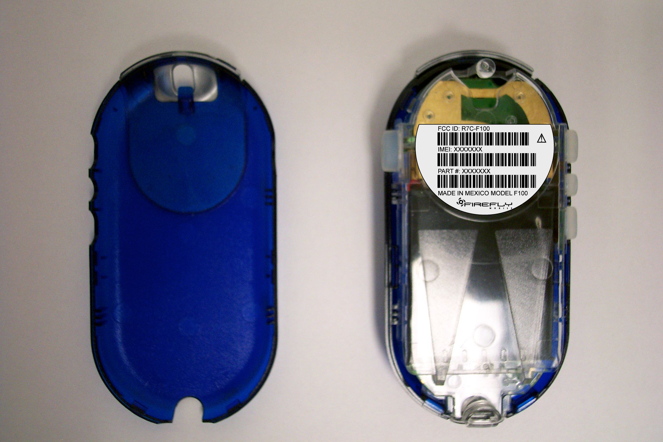
Close From: Marianne Bosley To: Chris Harvey; Marianne Bosley; Liming Xu Cc: Subject: RE: First RT forFirefly (Mobicom) MT#15502 Sent: 8/13/2004 12:44 PM Importance: Normal Below are the replies: 1.Page 37 of OET 65 Supplement C states “Should be at least 15 cm deep.” So 18 cm should be ok. 2.According to client;s email – “This device is a voice only phone for kids. It doesn’t have the GPRS capability. This voice only phone supports four vocoders: FR, HR, EHR and AMR, and the maximum number of the uplink time slot is one.” 3. Please see attached revised manual. 4. Please see attached revised manual. 5.Please see attached revised block diagram. 6.Reports have been corrected. 7.Please see attached revised label. 8.Please see attachments. 9. Please see attached electronic parts list – is mechanical parts list necessary also? 10. This has been corrected in report. 11. This has been added to page 44 of SAR report. 12. This has been corrected. The probe angle issue please see attached file. -----Original Message----- From: Chris Harvey [mailto:[email protected]] Sent: Friday, August 06, 2004 1:49 PM To: 'Marianne Bosley'; 'Liming Xu' Subject: RE: First RT forFirefly (Mobicom) MT#15502 Here are the final/consolidated information requests for the above referenced application: 1. SAR report shows 18cm depth in flat phantom, per OET65 Supplement C should be 15cm +/- 0.5cm, although z-scan plot shows no reflection problems. 2. This device is a cell phone for kids, does it have GPRS capability? What Class is it (how many uplink Page 1 of 3RE: First RT forFirefly (Mobicom) MT#15502 8/13/2004https://www.metlabs.com/exchange/forms/IPM/NOTE/read.asp?command=open&obj=... time slots)? 3. The manual RF Exposure statement has x’s for the SAR values, need actual numbers if they are going to put numbers. 4. There is no body-worn statement in the manual, need to include...report shows 0cm spacing, which means any holster must have no metallic, and statement must indicate this. Here is an example of an acceptable body-worn statement: Body-Worn Operation This device was tested for SAR compliance with 0cm separation to the body. Third party belt-clips, holsters, and similar accessories containing metallic components should not be used. For more information about RF exposure, visit the FCC website at www.fcc.gov 5. The Block Diagram indicates that the GSM850 band is Tx 890-915MHz, Rx 935-960MHz, needs to be corrected. 6. If the report is being revised, the following items should be corrected: a. RF report Pt. 22 spurious scans up to 18GHz per text but data only to 8.5GHz, which is OK. b. Frequency Stability for handheld battery operated units need to be tested to the battery end point per FCC 2.1055(d)(2). The summary in the report indicates that battery not applicable and AC applicable, but data has battery end point data, passes in both 22H and 24E modes! 7. The label exhibit states that the label is inside the phone, but I can not tell exactly where it will be located. It must be visible at the time of purchase (inside battery compartment is OK for cell). Please clarify, preferably with a photograph. 8. Please provide exhibits for SAR Dipole Calibration and SAR Probe Calibration information. 9. Please provide a parts list. 10. SAR report uses 1850.2MHz as lowest channel, but REF report uses 1850.4MHz. Please explain. Page 2 of 3RE: First RT forFirefly (Mobicom) MT#15502 8/13/2004https://www.metlabs.com/exchange/forms/IPM/NOTE/read.asp?command=open&obj=... 11. The description of the Box Phantom does not include thickness or dimensions. Please include this into the SAR report (update template). 12. The Measurement Uncertainty in the SAR report is calculated to be 27.5% in the table, but listed as 25.9% in the text below the table. Please correct this discrepancy. Additionally, please explain if the probe angle, which is assumed to be greater than 30% for the upright phantom, has been properly accounted for in the Measurement Uncertainties. Chris Harvey Firefly_Block Diagram_R1.pdf Firefly_Label_LabelExample4.jpg Firefly_Menu_Firefly instructions draft1_R1.pdf SN0107cal1.pdf VPM SAR probe.pdf Firefly_Part List_Electronic_BM-FF-ALA-0403.xls 900 dipole cal certificate sn0050.doc 1800 dipole cal certificate sn0012.doc Page 3 of 3RE: First RT forFirefly (Mobicom) MT#15502 8/13/2004https://www.metlabs.com/exchange/forms/IPM/NOTE/read.asp?command=open&obj=...
Cover Letter(s)
Chris Harvey From: Liming Xu [[email protected]] Sent: Friday, August 20, 2004 4:32 PM To: 'Chris Harvey'; Marianne Bosley; Liming Xu Cc: Shari Meyers Subject: RE: Further Information needed for Mobicom MT#15502 Page 1 of 1 8/21/2004 Hi Chris, Here is the response: 1) We have noticed that several Motorola and Nokia models ship with the battery cover on and the FCC ID printed on the box. So the FCC ID is located on the box and under the battery cover. Please ask if this is an option for Firefly. Best Regards, John Huang Mobicom Corp. 732-772-2233 (Office) 732-604-0839 (Mobile) [email protected] 2) Jim Doudrick will email you The 900MHz and 1800MHz dipole calibrations plots. Best Regards Liming -----Original Message----- From: Chris Harvey [mailto:[email protected]] Sent: Monday, August 16, 2004 11:09 AM To: 'Marianne Bosley'; Liming Xu Cc: Shari Meyers Subject: Further Information needed for Mobicom MT#15502 Marianne and Liming, I have reviewed the additional information submitted in response to the Request for Technical information of August 6 th , 2004 and find that the following still needs to be addressed: 1) Previous item number 7 requested clarification for the label location which was provided in the form of a photograph. This photograph seems to show the label inside the phone, which would be covered by an opaque plastic covering. This area does not appear to be a location that would be visible at the time of purchase nor a panel that would be opened to install/remove a battery or SIMM card. Thus this location seems to be one that would not be acceptable to the FCC. Please correct me if I have misunderstood where the label is being placed or the visibility during purchase/use. 2) The 900MHz and 1800MHz dipole calibrations were performed in February 2002 (with an indication that calibration was due again in February 2004). Please provide evidence of the dipole’s proper calibration for the tests performed in June 2004. Please contact me if you have any questions. Best regards, Chris Harvey
RF Exposure Info
Indexsar Report No. IXS0224 Date: 27 th September 2003 ISOTROPY VARIATIONS OF SAR PROBES PRESENTED WITHIN +/- 30 DEGREES TO THE LOCAL FIELD GRADIENT DIRECTIONS MI Manning, Indexsar Ltd. Introduction SAR probes with 3 diode-sensors in an orthogonal arrangement are designed to display an isotropic response when exposed to a uniform field. However, the probes are ordinarily used for measurements in non-uniform fields and isotropy is not assured when the field gradients are significant compared to the dimensions of the tip containing the three orthogonally-arranged dipole sensors. The uncertainties arising and a new method of correcting for them, were discussed in detail in a previous Indexsar paper [1], IXS0223 (dated 16 th May 2003). Another prevalent method of managing the uncertainties arising from field gradient effects is to constrain the probe axis presentation angle to be within 30 degrees to the local normal to the phantom surface. In this present report, analyses similar to those given earlier [1] are set out for the case where the probe is pointing towards the source to investigate the isotropy control afforded by probe angle restriction schemes. In the current analysis, the source used will be a balanced dipole aligned along the X-axis of the diagram below. The probe axis is referenced to the normal to the phantom surface (at the bottom) and the source dipole arms are parallel with and below the phantom bottom wall. Figure 1: Coordinate system and angular reference points In the Figure 1, θ is the angle of rotation of the source dipole with respect to the Y direction. Φ is the angle between the sensor location and the direction of the source. α is the sensor dipole angle from horizontal (this can be of either sign depending on the probe construction). r eff is the effective sensor radius within the probe tip. Unit direction vectors for the source dipole and for the sensor dipole can be described as below source dipole unit vector: X d =0; Y d = cosθ; Z d = sinθ sensor dipole unit vector: X s = cosΦ.cosα; Y s = sinΦ.cosα; Z s = sinα Page 1 of 1 email: [email protected] http://www.indexsar.com Oakfield House, Cudworth Lane, Newdigate, Surrey, RH5 5BG, UK. Indexsar Report No. IXS0224 Date: 27 th September 2003 The sensor sensitivity is given by the cosine of the angle between them sensor sensitivity = | X d X s + Y d Y s + Z d Z s | = |(0 + cosθ.cosΦ.cosα + sinθ.sinα)| where the absolute value is taken since the sensor output is rectified. The magnitude of the local E-field also needs correction for position of the sensor down the field gradient distance correction = e -r eff .dr. sinθ.cosΦ Where r eff is the effective sensor radius, dr is the attenuation constant (= 1/ skin depth. See definitions in P1528 Section 3) and Φ is the sensor rotation from the source direction. For probe output which is (when linearised) proportional to E 2 or SAR, distance correction = e -2.r eff .dr. sinθ.cosΦ The equations above allow us to calculate the variation of output of a diode sensor, U sensor , with probe rotation angle and the angle between the probe axis and the field gradient direction U sensor = U centre |( cosθ.cosΦ.cosα + sinθ.sinα)| e -2.r eff .dr. sinθ.cosΦ where U centre is the value of the field at the centre of the probe tip This equation can be used three times at angles 2π/3 apart to predict the isotropic response of a 3-channel probe in field gradients of different magnitude as shown in Figure 2. 0 60 120 180 240 300 360 -9 0 -6 0 -3 0 0 30 60 90 -6 -4 -2 0 2 4 6 E rro r [ d B ] probe rotation angle Φ Probe angle to field gradient direction θ Figure 2: Predicted isotropic response of 5mm probe with an effective sensor radius of 1.25mm and a sensor angle of 35.3 degrees with the source below the probe. The result shown is for a penetration depth of 9mm corresponding to 2450MHz box testing. The max. spherical isotropy range predicted is + 0.91dB. Page 2 of 2 email: [email protected] http://www.indexsar.com Oakfield House, Cudworth Lane, Newdigate, Surrey, RH5 5BG, UK. Indexsar Report No. IXS0224 Date: 27 th September 2003 Figure 2 can be compared with the similar presentation given in [1] for the situation of the source at the side of the probe. This is reproduced as Figure 3. 0 30 60 90 120 150 180 0 120 240 -6.00 -4.00 -2.00 0.00 2.00 4.00 6.00 dB φ (polarization rotation) θ (probe rotation) Figure 3: Predicted isotropic response from [1] of probe with an effective sensor radius of 1.25mm and a sensor angle of 35.3 degrees. The result shown is for a penetration depth of 9mm corresponding to 2450MHz box testing. The probe rotation is offset by 20 degrees to correspond with the measured data. The max. spherical isotropy range predicted is +/- 1.1227dB. Comparison of experimental measurements with the theory A measured directivity pattern for a 6.8mm diameter probe is given in [2]. This is reproduced here as Figure 4. Figure 4: Measured isotropic response from [2] of a 6.8mm diameter probe in brain tissue simulating liquid at 900MHz. The dipole was positioned normal to the probe axis and then tilted by up to 60 degrees. Page 3 of 3 email: [email protected] http://www.indexsar.com Oakfield House, Cudworth Lane, Newdigate, Surrey, RH5 5BG, UK. Indexsar Report No. IXS0224 Date: 27 th September 2003 The geometrical theory presented here can be used to make a prediction of the response obtained by Pokovic [2] in Figure 4. Using the same ratio of effective sensor radius to probe diameter, the result obtained is shown in Figure 5. 0 60 120 180 240 300 360 0 6 0 -1.00 -0.80 -0.60 -0.40 -0.20 0.00 0.20 0.40 0.60 0.80 1.00 E rro r [ d B ] probe rotation angle Φ θ Figure 5: Theoretical isotropic response of a 6.8mm diameter probe in brain tissue simulating liquid at 900MHz. The dipole is positioned normal to the probe axis and then tilted by up to 60 degrees. The isotropy range from 0 to 60 degrees is 0.39dB. Along with the measurements presented in [1], comparison of Figures 4 …
Text truncated - open the document above for the full version.
RF Exposure Info
IMMERSIBLE SAR PROBE CALIBRATION REPORT Part Number: IXP – 050 S/N 0107 15 th July 2003 Indexsar Limited Oakfield House Cudworth Lane Newdigate Surrey RH5 5DR Tel: +44 (0) 1306 631 233 Fax: +44 (0) 1306 631 834 e-mail: [email protected] INTRODUCTION This Report presents measured calibration data for a particular Indexsar SAR probe (S/N 0107) and describes the procedures used for characterisation and calibration. Indexsar probes are characterised using procedures that, where applicable, follow the recommendations of CENELEC [1] and IEEE [2] standards. The procedures incorporate techniques for probe linearisation, isotropy assessment and determination of liquid factors (conversion factors). Calibrations are determined by comparing probe readings with analytical computations in canonical test geometries (waveguides, boxes and spheres) using normalised power inputs. Each step of the calibration procedure and the equipment used is described in the sections below. CALIBRATION PROCEDURE 1. Equipment Used For the first part of the calibration procedure, the probe is placed in a calibration jig as pictured in Figure 1. In this position the probe can be rotated about its axis by a non-metallic belt driven by a stepper motor. The probe is attached via its amplifier and an optical cable to a PC. A schematic representation of the test geometry is illustrated in Figure 2. A balanced dipole (900 or 1800 MHz) is inserted horizontally into the bracket attached to a second belt (Figure 1). The dipole also can be rotated about its axis. A cable connects the dipole to a signal generator, via a directional coupler and power meter. The signal generator feeds an RF amplifier at constant power, the output of which is monitored using the power meter. The probe is positioned so that its sensors line up with the rotation center of the source dipole. By recording output voltage measurements of each channel as both the probe and the dipole are rotated, the spherical isotropy of the probe can be determined. The calibration process requires E-field measurements to be taken in air, in 900 MHz simulated brain liquid and at other frequencies/liquids as appropriate. When it is necessary to place the probe in liquid, a rectangular box made from PMMA (200mm internal width, 200mm internal height and 100mm internal depth; wall thickness 4mm) is filled with the appropriate liquid and positioned on the stand so that the probe tip is positioned within the liquid (Figure 1). The box is positioned so that its outer surface is 2mm from the dipole. The procedure follows that described in Ref [2]. Section A.5.2.1. 2. Linearising probe output The probe channel output signals are linearised in the manner set out in Refs [1] and [2]. The following equation is utilized for each channel: 2 U lin = U o/p + U o/p 2 / DCP (1) where U lin is the linearised signal, U o/p is the raw output signal in voltage units and DCP is the diode compression potential in similar voltage units. DCP is determined from fitting equation (1) to measurements of U lin versus source feed power over the full dynamic range of the probe. The DCP is a characteristic of the schottky diodes used as the sensors. For the IXP-050 probes the DCP values are typically 0.10V (or 20 in the voltage units used by Indexsar software, which are V*200). 3. Optimizing channel sensitivity factors in air The first step of the calibration process is to calibrate the Indexsar probe to a W&G EMR300 E-field meter in air. The principal reasons for this are to balance the channels in air and to obtain air factors that are used in subsequent steps of the calibration procedure. It should be noted that the air factors are not separately used for normal SAR testing. The probe and a 900 MHz standard dipole are positioned in the calibration jig as outlined in the section above. With the Indexsar probe located in air, individual channel output voltages are recorded as probe and dipole are rotated. An ‘air factor’ is applied to each of the probe’s three channels in order to equilibrate the peak magnitudes of each channel. A multiplier is applied to factors to bring the magnitudes of the average E-field measurements as close as possible to those of the W&G probe. The following equation is used (where linearised output voltages are in units of V*200): E air 2 (V/m) = U linx * Air Factor x + U liny * Air Factor y + U linz * Air Factor z (2) It should be noted that the IXP-050 probes are optimised for use in tissue simulating liquids and do not behave isotropically in air. 4. 900 MHz Liquid Calibration The second phase of calibration requires the channel output voltages of the Indexsar probe to be measured in a box filled with 900 MHz simulated brain liquid, balanced to optimise the probe isotropy. Later, the conversion factors are determined either using a waveguide or by comparison to a reference probe that has been calibrated by NPL. The box of liquid is placed on the stand as described above and as pictured in Figure 1. Channel outputs for the different orientations of probe and dipole are recorded and entered into a spreadsheet. These measurements are multiplied by the previously determined air factors. Another factor, referred to as the ‘liquid factor’ is also applied to the measurements of each channel. The magnitude of the liquid factor for each channel is selected so as to optimise the isotropy of the probe (i.e. balance the peak magnitudes of the three channels) 3 in the liquid. The following equation is used (where output voltages are in units of V*200): E liq 2 (V/m) = U linx * Air Factor x * Liq Factor x + U liny * Air Factor y * Liq Factor y + U linz * Air Factor z * Liq Factor z (3) An automated optimisation program balances the channel factors and then performs an optimisation to minimise the probe isotropy across the whole range of angles of presentation of the source field. A 3D representation of the spherical isotropy for probe S/N 0107 is shown in Figure 3. The rotational isotropy…
Text truncated - open the document above for the full version.
RF Exposure Info
These are the results from our recent functional verification of the Dipole antennas used exclusively in the validation of our SAR system. Provided below are plots provided by the manufacturer, followed by the results of our verification. 900MHZ Dipole MFR return loss Data 900 MHz validation return loss data 8/20/2004 1800MHZ Dipole MFR return loss Data 1800MHz dipole validation return loss data 8/20/2004 2450MHz dipole MFR return loss data. 2450 dipole verification return loss data 8/20/2004
RF Exposure Info
Company Reg No. 4075046 Reg. Office: Oakfield House, Cudworth Lane, Newdigate, Surrey RH5 5DR.. Directors: D Riley and MI Manning PhD. Indexsar Limited Oakfield House Cudworth Lane Newdigate Surrey RH5 5DR Tel: +44 (0) 1306 631 233 Fax: +44 (0) 1306 631 834 e-mail: [email protected] Calibration / Conformance statement Balanced Validation dipole Type: IXD-090 900MHz Manufacturer: IndexSAR, UK Serial Number: 0050 Place of Calibration: IndexSAR, UK IndexSAR Limited hereby declares that the IXD series dipole named above has been checked for conformity to the specifications given in the draft IEEE 1528 and CENELEC En 50361 standards on the date shown below. Date of Calibration/Check: 1 st February 2002 The dipole named above should be periodically re-checked using the procedures set out in the dipole calibration document. It is important that the cautions regarding handling of the dipoles (given in the calibration document) are adhered to. Next Calibration Date: February 2004 The calibration measurements were carried out using the methods described in the calibration document. Where applicable, the standards used in the calibration process are traceable to the UK’s National Physical Laboratory. Calibrated By: Approved By:
RF Exposure Info
Company Reg No. 4075046 Reg. Office: Oakfield House, Cudworth Lane, Newdigate, Surrey RH5 5DR.. Directors: D Riley and MI Manning PhD. Indexsar Limited Oakfield House Cudworth Lane Newdigate Surrey RH5 5DR Tel: +44 (0) 1306 631 233 Fax: +44 (0) 1306 631 834 e-mail: [email protected] Calibration / Conformance statement Balanced Validation dipole Type: IXD-180 1800MHz Manufacturer: IndexSAR, UK Serial Number: 0012 Place of Calibration: IndexSAR, UK IndexSAR Limited hereby declares that the IXD series dipole named above has been checked for conformity to the specifications given in the draft IEEE 1528 and CENELEC En 50361 standards on the date shown below. Date of Calibration/Check: 1 st February 2002 The dipole named above should be periodically re-checked using the procedures set out in the dipole calibration document. It is important that the cautions regarding handling of the dipoles (given in the calibration document) are adhered to. Next Calibration Date: February 2004 The calibration measurements were carried out using the methods described in the calibration document. Where applicable, the standards used in the calibration process are traceable to the UK’s National Physical Laboratory. Calibrated By: Approved By:
Test Report
MET Laboratories, Inc. Safety Certification - EMI - Telecom Environmental Simulation 914 W. Patapsco Avenue ! BALTIMORE, MD 21230 ! PHONE (410) 354-3300 ! FAX (410) 354-3313 August 3, 2004 Mr. Joe Murphy Firefly Mobile 250 Parkway Drive, Suite 220 Lincolnshire, IL 60069 Reference: Firefly Spark F100 FCC ID: R7C-F100 Dear Mr. Joe Murphy: Enclosed is the EMC Test Report for the Firefly Mobile Firefly Spark F100. The Firefly Mobile Firefly Spark F100 was tested to the requirements of the FCC Rules and Regulations, Part 22 of Title 47 of the CFR, for a Broadband PCS device. Thank you for using the testing services of MET Laboratories. If you have any questions regarding these results or if MET can be of further assistance to you, please feel free to contact me. We appreciate your business and look forward to working with you again soon. Kindest Regards, MET LABORATORIES, INC. Marianne T. Bosley TCB Administrator Enclosures: (Firefly Mobile EMC15502-FCC 22) DOCTEM-23 Dec 2003 Certificates and reports shall not be reproduced except in full, without the written permission of MET Laboratories, Inc. While use of the National Voluntary Laboratory Accreditation Program (NVLAP) letters or the NVLAP Logo in this report reflects the MET Accreditation under the NVLAP Program, these letters, logo, or Statements do not claim product endorsement by NVLAP or any Agency of the U.S. Government. Firefly Mobile Firefly Spark F100 FCC ID: R7C-F100 August 3, 2004 Electro-Magnetic Compatibility Test Report for the Firefly Mobile Firefly Spark F100 Tested Under FCC Part 22 Title 47 of the CFR for Broadband PCS Devices MET REPORT: EMC15502-FCC 22 August 3, 2004 PREPARED FOR: Firefly Mobile 250 Parkway Drive, Suite 220 Lincolnshire, IL 60069 PREPARED BY: MET Laboratories, Inc. 914 West Patapsco Avenue Baltimore, Maryland 21230-3432 Copyright 2004, MET Laboratories, Inc. This report shall not be reproduced except in full, without the express written consent of MET Laboratories, Inc., nor shall this report, or any copy thereof be provided to a competitor of MET Laboratories, Inc. Firefly Mobile Firefly Spark F100 FCC ID: R7C-F100 August 3, 2004 MET# EMC15502-FCC 22 Copyright 2004, MET Laboratories, Inc. Page i of vi Electro-Magnetic Compatibility Test Report for the Firefly Spark F100 Tested Under FCC Part 22 Title 47 of the CFR for Broadband PCS Devices MET REPORT: EMC15502-FCC 22 PREPARED FOR: Firefly Mobile 250 Parkway Drive, Suite 220 Lincolnshire, IL 60069 _______________________________ Len Knight, Manager Electromagnetic Compatibility Test…
Text truncated - open the document above for the full version.
Contact Information
Applicant
David J Theobald(Director of Handset Development)
Test Firm
MET Laboratories, Inc.Robert Frier
Technical Specifications
| # | Rule Parts | Frequency Range | Power Output | Emission | Tolerance |
|---|---|---|---|---|---|
| 2 | 22H | 824.2 MHz - 848.8 MHz | 1.047 W | 285KGXW | 1 ppm |
Other Applications from Firefly Mobile Inc.
R7CR100
Sep 10, 2007Dual-band GSM 850 / PCS 1900 Mobile Phone
Equipment Class
PCE - PCS Licensed Transmitter held to ear
R7C-C100
Dec 28, 2005Dual-Band CDMA Phone
Equipment Class
PCE - PCS Licensed Transmitter held to ear