R7DLD-42IU21LCD TV Monitor
IND Tek Co., Ltd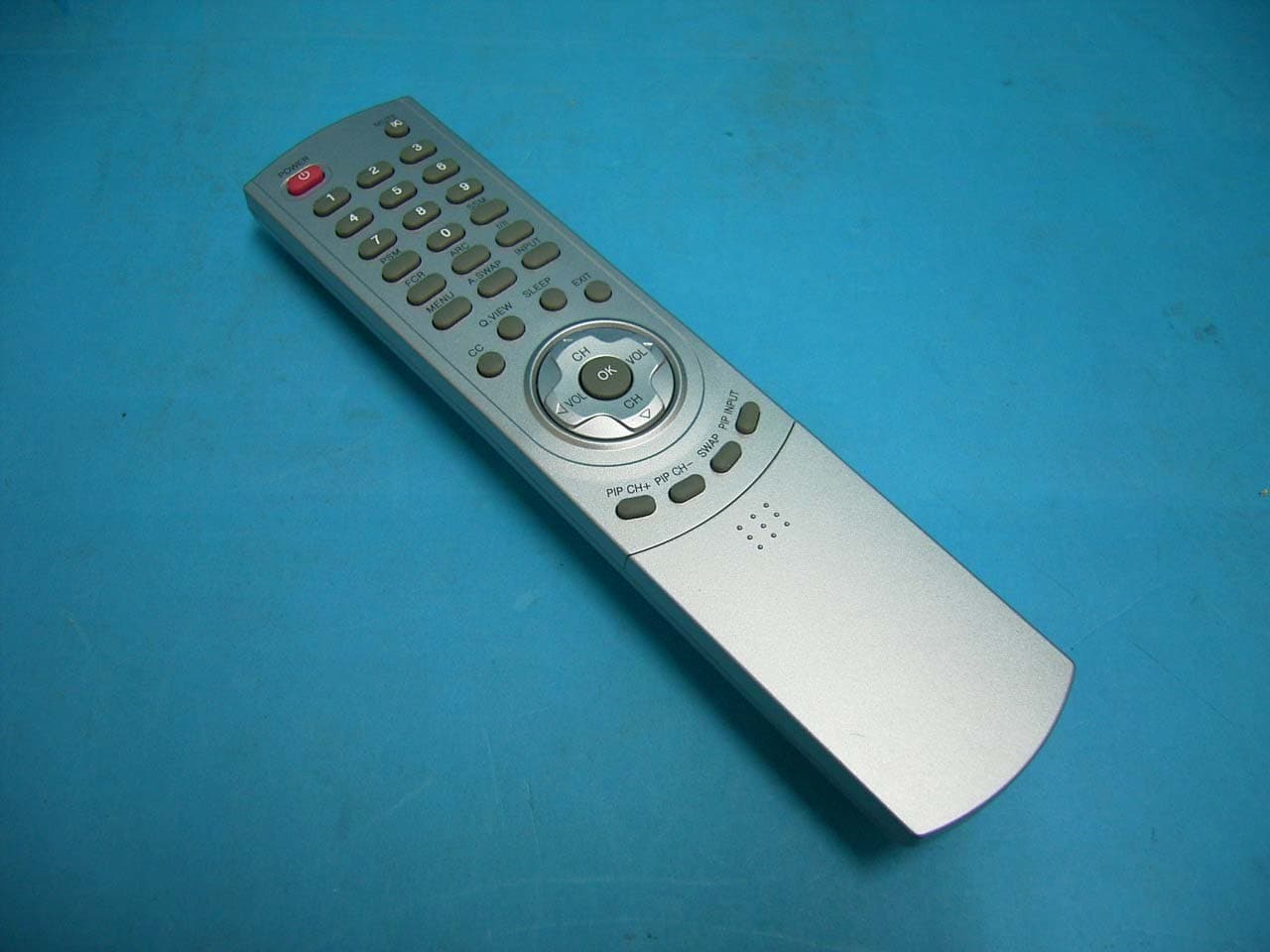
Click to zoom
Application Details
- Equipment Class
- JBP - Part 15 Class B Computing Device Peripheral
- Date of Grant
- Jan 29, 2006
- Application Purpose
- Original Equipment
- Date of Application
- Jan 29, 2006
- Equipment Note
- LCD TV Monitor
- Company
- IND Tek Co., Ltd
- Country
- South Korea
Documents & Files
Document Text
Text extracted from the exhibit documents filed with the FCC. Open a document above to read the original.
Users Manual
P lea s e rea d this ma nua l ca refully before opera ting your s et.R eta in it for future reference.S ee the la bel a tta ched on the ba ck cover a nd quote this infor-ma tion to your dea ler when you require s ervice. L D- 42 IU 2 1 C olour T elev is ion C olour T elev is ion O wner Õ s Ma nua l P /N O : MAN 05G DP 045 WARNING : TO PREVENT FIRE OR SHOCK HAZARDS, DO NOT EXPOSETHIS PRODUCT TO RAIN OR MOISTURE.NOTE TO CABLE/TV INSTALLER: This reminder is provided to call the CATV system installer’sattention to Article 820-40 of the National Electric Code(U.S.A.). The code provides guidelines for proper groundingand, in particular, specifies that the cable ground shall be con-nected to the grounding system of the building, as close to thepoint of the cable entry as practical. REGULATORY INFORMATION This equipment has been tested and found to comply with thelimits for a Class B digital device, pursuant to Part 15 of theFCC Rules. These limits are designed to provide protectionagainst harmful interference in a residential installation. Thisequipment generates, uses and can radiate radio frequencyenergy and, if not installed and used in accordance with theinstructions, may cause harmful interference to radio communi-cations. However, there is no guarantee that interference willnot occur in a particular installation. If this equipment doescause harmful interference to radio or television reception, which can be determined by turning the equipment off and on,the user is encouraged to try to correct the interference by oneor more of the following measures:- Reorient or relocate the receiving antenna.- Increase the separation between the equipment and receiver.- Connect the equipment into an outlet on a circuit different fromthat to which the receiver is connected.- Consult the dealer or an experienced radio/TV technician forhelp.Any changes or modifications not expressly approved by theparty responsible for compliance could void the user’s authori-ty to operate the equipment. Warning 2 CAUTION RISK OF ELECTRIC SHOCK DO NOT OPEN WARNING : TO REDUCE THE RISK OF ELECTRIC SHOCK DO NOT REMOVE COVER (OR BACK). NO USER SERVICE-ABLE PARTS INSIDE. REFER TO QUALIFIED SERVICE PERSONNEL. The lightning flash with arrowhead symbol, within an equilateral triangle, is intended to alert the user tothe presence of uninsulated “dangerous voltage” within the product’s enclosure that may be of sufficientmagnitude to constitute a risk of electric shock to persons. The exclamation point within an equilateral triangle is intended to alert the user to the presence of impor-tant operating and maintenance (servicing) instructions in the literature accompanying the appliance. Important S afety Ins tructionS 1) R ea d thes e ins tructions . 2) K eep thes e ins tructions . 3) H eed a ll wa rnings . 4) F ollow a ll ins tructions . 5) Do not us e this a ppa ra tus nea r wa ter. 6) C lea n only with dry cloth. 7) Do not block a ny ventila tion openings . Ins ta ll in a ccorda nce with the ma nufa cturer's ins tructions . 8) Do not ins ta ll nea r a ny hea t s ources s uch a s ra dia tors , hea t regis ters , s toves , or other a ppa ra tus (including a mplifiers ) tha t produce hea t. 9) Do not defea t the s a fety purpos e of the pola riz ed or grounding-type plug. A pola riz ed plug ha s two bla des with one wider tha n the other. A grounding type plug ha s two bla des a nd a third grounding prong. T he wide bla de or the third prong a re provided for your s a fety. If the provided plug does not fit into your outlet, cons ult a n electricia n for repla cement of the obs olete outlet. 10) P rotect the power cord from being wa lked on or pinched pa rticula rly a t plugs , convenience recepta cles , a nd the point where they exit from the a ppa ra tus . 11) O nly us e a tta chments /a cces s ories s pecified by the ma nufa cturer. 12) U s e only with the ca rt, s ta nd, tripod, bra cket, or ta ble s pecified by the ma nufa cturer, or s old with the a ppa ra tus . When a ca rt is us ed, us e ca ution when moving the ca rt/a ppa ra tus combina tion to a void injury from tip-over. . 13) U nplug this a ppa ra tus during lightning s torms or when unus ed for long periods of time. 14) R efer a ll s ervicing to qua lified s ervice pers onnel. S ervicing is required when the a ppa ra tus ha s been da ma ged in a ny wa y, s uch a s power-s upply cord or plug is da ma ged, liquid ha s been s pilled or objects ha ve fa llen into the a ppa ra tus , the a ppa ra tus ha s been expos ed to ra in or mois ture, does not opera te norma lly, or ha s been dropped. - T he a ppa ra tus s ha ll not be expos ed to dripping or s pla s hing a nd tha t no objects filled with liquids , s uch a s va s es , s ha ll be pla ced on the a ppa ra tus . - Minimum dis ta nces (e. g. 10cm) a round the a ppa ra tus for s ufficient ventila tion “WARNING – To reduce the risk of fire or electric shock, do not expose the apparatus to rain or moisture.” “The apparatus shall not be exposed to dripping or splashing and no objects filled with liquids, such as vases, shall be placed on the apparatus." Warnings 2 Safety Instructions 3-5 Contents 6 Location and function of controls 7-10 Remote control handsetBattery installationFront panelBack panelConnection to External equipment 11-15 Basic operation 16 On and Off / Programme selectionVolume adjustmentOn screen language selection (option)On screen menus 17 Menu selectionSetting up TV stations 18-20 Memorizing the Channels with AutoAdd/Delete Channels with ManualFine Tuning Adjustment / BOOSTERFavorite Channels SetupPicture Menu 21-23 CSM (Colour Status Memory)PSM (Picture Status Memory)Manual Picture ControlPicture FormatSound Menu 24-27 SSM (Sound Status Memory)Balance AVL (Auto Volume Leveler)SPDIF FormatStereo/SAP Broadcasts SetupAudio LanguageTime Menu 28-31 ClockOn/Off TimeAuto sleep Time ZoneSleep timer Setup Menu 32 Child lockCaption Menu 33-34 Caption On/OffAnalog CAP/TXTDTV CAP SetupDTV CAP ColorLock Menu (option) 3…
Text truncated - open the document above for the full version.
Block Diagram
(주)인디텍 Block Diagram MST5151A VCT49xyI LCD PANEL MP7720×2 S-VIDIO COMP (RCA_L/R) TUNER AV1AV2 CXA2069 SCART1_VI/LI/RI COMP_L PC (DSUB-15) 74HCT08 PC_HS PC_VS PC_R/G/B SRAM-8Mbit L_SPK L - 2IU 1 Block Diagram PC/DVI_AUDIO JACK PC_AUDIO_L DTV-Y/C D-TV SVHS_Y/C DTV-CVBS TAGC DTV_AUDIO_L/R DVI L R_SPK PC_AUDIO_R COMP_R R 1,2,46 17,19 COMP_Y 2224,2623,2530 TV_V TV_L/R 59 TV_O 63 62,64 122,121 TV_L/R L_SPK R_SPK 124123 TAGC 112 AUDIO_R/L 52,54 PC_AUDIO_R/L 117,118115,116 COMP_R/L 113,114109,110 SCART2_VI/LI/RI 8,9,111343,4544 CVBS_S Y_OUT_S 41 CVBS_M 53 60 39 C_OUT_S 37 Y_OUT_M 56 C_OUT_M 58 6263 SCART_FB/R/G/B 138,139,140,141 TV_V1 TW9918 TV_V1 64 CVBS_M Y_OUT_M C_OUT_M 616056 SCART_FB/R/G/B 69,74,77,81 COMPONENT DTV_Y/Pb/Pr(480i,480p,720p,1080i) 31,28,33 PC_HS PC_VS 24LC21 I2C 24LC02 I2C PC_HS PC_R/G/B PC_VS 18 19 20,23,25 RxC-/RxC+, Rx0-/Rx0+ Rx1-/Rx1+, Rx2-/Rx2+ RxC-/RxC+, Rx0-/Rx0+ Rx1-/Rx1+, Rx2-/Rx2+ I2C 3,2,208,2079,8,6,514,15 Flash-4Mbit ADB[0..19] ADB[0..19] SDRAM-16M TAD[0..10] Tx0-/Tx0+Tx1-/Tx1+Tx2-/Tx2+TxC-/TxC+Tx3-/Tx3- TDQ[0..15] ITU-R 656[Y1,7 ... 0] 28 ... 35 ITU-R 656[Y,7 ... 0] DECCLK 71..75,78..80 83 5248 ... 41 VAPCLK 53 25 61 ... 54 Key DDR SDRAM AD_Key2 AD_Key1TX_INTLED_R/G 464544 39 4081 RXD_UARTTXD_UART 82 BSS83 CNTL_SCL CNTL_SDA SCL_ASDA_A SIF X-TAL20.25MHz X-TAL14.318MHz X-TAL27MHz
Cover Letter(s)
● HQ Bloc 11-1, Lot35, Koogka 4 danji, Kumi-City, Kyongbuk, Korea. Tel:+82-54-473-1831∼6 Fax:+82-54-473-1837 ● Seoul Br. R/No. 1202,Ace Techno Tower 8, 191-7, Kuro-Dong, Kuro-Ku, Seoul, Korea. September 21, 2005 Compliance Certification Services Certification Division 561F Monterey Road Morgan Hill, CA 95037 To whom it may concern: We, the undersigned, hereby authorize IST Co., Ltd., to act on our behalf in all manners relating to application for equipment authorization, including signing of all documents relating to these matters. Any and all acts carried out by IST Co., Ltd. on our behalf shall have the same effect as acts of our own. We, the undersigned, hereby certify that we are not subject to a denial of federal benefits, that includes FCC benefits, pursuant to Section 5301 of the Anti-Drug Abuse Act of 1988, 21 U.S.C. 853(a). In authorizing IST Co., Ltd. as our agent, we still recognize that we are responsible to: a) comply with the relevant provisions of the certification program; b) make all necessary arrangements for the conduct of the evaluation, including provision for examining documentation and access to all areas, records (including internal audit reports) and personnel for the purposes of evaluation (e.g. testing, inspection, assessment, surveillance, reassessment) and resolution of complaints; c) make claims regarding certification only in respect of the scope for which certification has been granted; d) do not use our product certification in such a manner as to bring the Certification Division into disrepute and not make any statement regarding our product certification which the Certification Division may consider misleading or unauthorized; ● HQ Bloc 11-1, Lot35, Koogka 4 danji, Kumi-City, Kyongbuk, Korea. Tel:+82-54-473-1831∼6 Fax:+82-54-473-1837 ● Seoul Br. R/No. 1202,Ace Techno Tower 8, 191-7, Kuro-Dong, Kuro-Ku, Seoul, Korea. e) upon suspension or cancellation of certification, discontinue use of all advertising matter that contains any reference thereto and return any certification documents as required by the Certification Division; f) use certification only to indicate the products are certified as being in conformity with specified standards; g) endeavor to ensure that no certificate or report nor any part thereof is used in a misleading manner; h) ensure that any reference to our product certification in communication media such as documents, brochures or advertising, complies with the requirements of the Certification Division; i) keep a record of all complaints made known to the us relating to the product’s compliance with requirements of the relevant standard and to make these records available to the Certification Division when requested; j) take appropriate action with respect to such complaints and any deficiencies found in products or services that affect compliance with the requirements for certification; k) document the actions taken. This authorization is valid until further written notice from the applicant. Sincerely Yours, Yun-Tae An/ Senior Engineer R&D / INDTEK CO., LTD.
ID Label/Location Info
ID Label Sample & Location Information
Test Report
IST Co., Ltd EMC LABORATORY TEST REPORT NO. : 06-IST-0036 1 of 23 Certification of Compliance CFR 47 Part 15 Subpart B Test Report File No. : 06-IST-0036 Date of Issue : January 26, 2006 FCC ID : R7DLD-42IU21 Model(s) : LD-42IU21 ■ Basic □ Alternate Kind of Product : LCD TV MONITOR Applicant : IND TEK Co., Ltd. Address : Bloc 11-1, Lot 35, Koogka 4 danji, Kumi-City, Kyoungbuk, Korea Manufacturer : IND TEK Co., Ltd. Address : Bloc 11-1, Lot 35, Koogka 4 danji, Kumi-City, Kyoungbuk, Korea Test Result ■ Positive □ Negative Reviewed By Approved By Comment(s) - Investigations requested : Measurement to the relevant clauses of FCC rules and regulations Part 15 Subpart B – Unintentional Radiators, Class B. - The test report with appendix consists of 23 pages. - The test result only responds to the tested sample. - It is not allowed to copy this report even partly without the allowance of IST EMC Laboratory. - This equipment as for has been shown to be capable of continued compliance with the applicable technical standards as indicated in the measurement report and was tested in accordance with the measurement procedures specified in ANSI C63.4 2003. S.J.Cho / EMC Group Manager J.H.Lee / Chief IST Co., Ltd EMC LABORATORY TEST REPORT NO. : 06-IST-0036 2 of 23 TABLE OF CONTENTS Table of contents 2 Information of test laboratory, Environmental conditions, Power supply system used, Product information 3 Descriptions of test Conducted Emission 4 Radiated Emission 5 Measurement Uncertainty Calculations 6 Equipment Under Test 7 Test Set-Up (Figure) 8 Summary 9 ■ Test Conditions and Data – Emissions ◆ Conducted Emissions 0.15MHz- 30MHz Applicable Test Conditions / Data and Plots 10-12 ◆ Radiated Emissions 30MHz - 1GHz Applicable Test Conditions / Data and Plots 13-19 Appendix A. The Photos of Test Setup 20-21 B. The Photos of Equipment Under Test 22-23 Note: IST Co., Ltd EMC LABORATORY TEST REPORT NO. : 06-IST-0036 3 of 23 INFORMATIONS OF TEST LABORATORY EMC LABORATORY of IST Co., Ltd. (FCC Filing Lab.) San 21-8, Goan-Ri, Baekam-Myun, Yongin-City Kyonggi-Do, 449-860, Korea TEL : +82 31 333 4093 FAX : +82 31 333 4094 ENVIRONMENTAL CONDITIONS Temperature 17.5 °C Humidity 34 % Atmospheric pressure 1014 mbar POWER SUPPLY SYSTEM USED Power supply system AC 120V, 60Hz (Refer to the product information) PRODUCT INFORMATION Type: 42Inch Flat Panel LCD Resolution(Max): 1600 x 1200, @60Hz Power: AC100~240, 50/60Hz, 240W - EMC suppression device is not used during the test . - Please refer to user’s manual. IST Co., Ltd EMC LABORATORY TEST REPORT NO. : 06-IST-0036 4 of 23 < Concept Drawing > 215 >150 >40 80 Receiver EUT LISN 80 ≥ 80 80 40 ≥ 80 Measuring apparatus Mains Filter Mains Rear side Equipment under test Coaxial cable Artificial mains networ k Screened room Non-metallic support 80 DESCRIPTIONS OF TEST Conducted Emissions: The measurement were performed over the frequency range of 0.15MHz to 30MHz using a 50 Ω /50uH LISN as the input transducer to a Spectrum Analyzer or a Field Intensity Meter. The measurements were made with the detector set for "Peak" amplitude within a bandwidth of 10KHz or for "quasi-peak" & “Average” within a bandwidth of 9KHz. - Procedure of Test The line-conducted facility is located inside a shielded room No.1. A 1m X 1.5m wooden table 80cm height is placed 40cm away from the vertical wall and 1.5m away from the other wall of the shielded room. The R/S 3725/2 and Hyup-Rip KNW-407 LISN are bonded to bottom of the shielded room. The EUT is located on the wooden table with distance more than 80cm from the LISN and powered from the LISN .The peripheral equipment is powered from the other LISN. Power to the LISNs are filtered by a noise cut power line filters. All electrical cables are shielded by braided tinned steel tubing with inner φ 1.2cm. If the EUT is a DC-powered device, power will be derived from the source power supply it normally will be powered from and this supply lines will be connected to the EMCO LISN. All interconnecting cables more than 1m were shortened by non-inductive bundling to a 1m length. Sufficient time for the EUT, support equipment, and test equipment was allowed in order for them to warm up to their normal operating conditions. The RF output of the LISN was connected to the R/S receiver to determine the frequency producing the maximum emission from the EUT. The frequency producing the maximum level was reexamined using Quasi-Peak mode by manual measurement, after scanned by automatic Peak mode for frequency range from 0.15 to 30MHz. The bandwidth of the receiver was set to 10kHz. The EUT, peripheral equipment, and interconnecting cables were arranged and manipulated to maximize each EME emission. < Side View > IST Co., Ltd EMC LABORATORY TEST REPORT NO. : 06-IST-0036 5 of 23 DESCRIPTION OF TEST Radiated Emissions: The measurement was performed over the frequency range of 30MHz to 1GHz using antenna as the input transducer to a Spectrum analyzer or a Field Intensity Meter. The measurement was made with the detector set for "quasi-peak" within a bandwidth of 120KHz. - Procedure of Test Preliminary measurements were made at 3 meter using bi-conical and log-periodic antennas, and spectrum analyzer to determine the frequency producing the max. emission in anechoic chamber. Appropriate precaution was taken to ensure that all emission from the EUT were maximized and investigated. The system configuration, mode of operation, turn-table azimuth and height with respect to the antenna were noted for each frequency found. The spectrum was scanned from 30MHz to 1000MHz using S/B LogBicon antenna VL9160. Under 30MHz, magnetic loop antenna were used. Final measurements were made at open site with 3-meters test distance using the same antenna. The OATS have been verified in regular for its normalized site attenuation. The test equipment was placed on a wooden table. Sufficient time for the EUT, peripheral equipment, and test equipment was allowed in order for them to warm up…
Text truncated - open the document above for the full version.
Contact Information
Applicant
Cheol-Gyu Kim(Manager)
Test Firm
IST Co., LtdBong Kyoon Bae
Technical Specifications
| # | Rule Parts | Frequency Range | Power Output |
|---|---|---|---|
| 1 | 15B | - | - |
Other Applications from IND Tek Co., Ltd
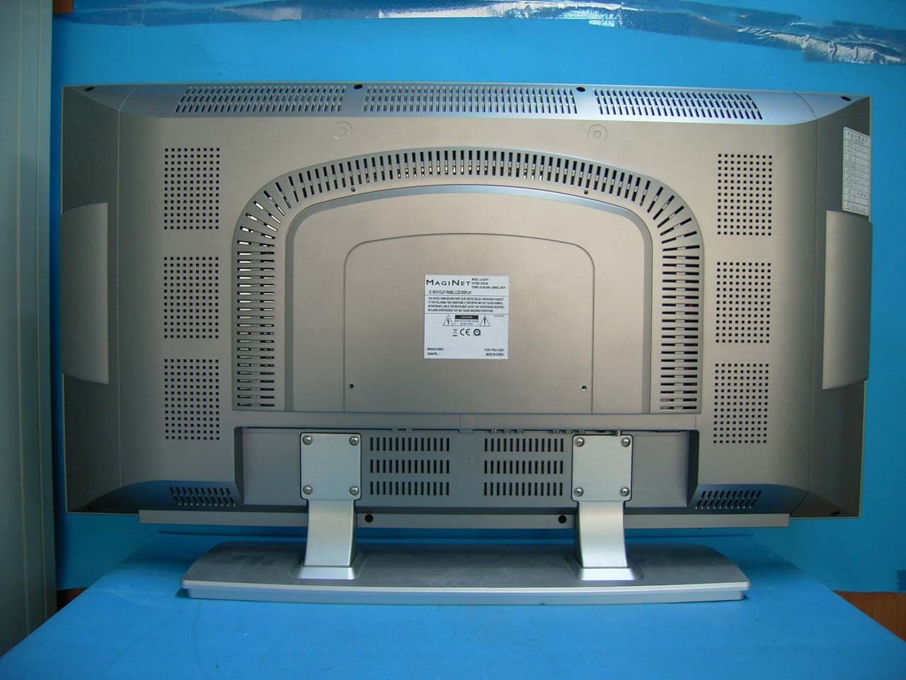
R7DLC-32IU21
Dec 07, 2005LCD TV Monitor
Equipment Class
JBP - Part 15 Class B Computing Device Peripheral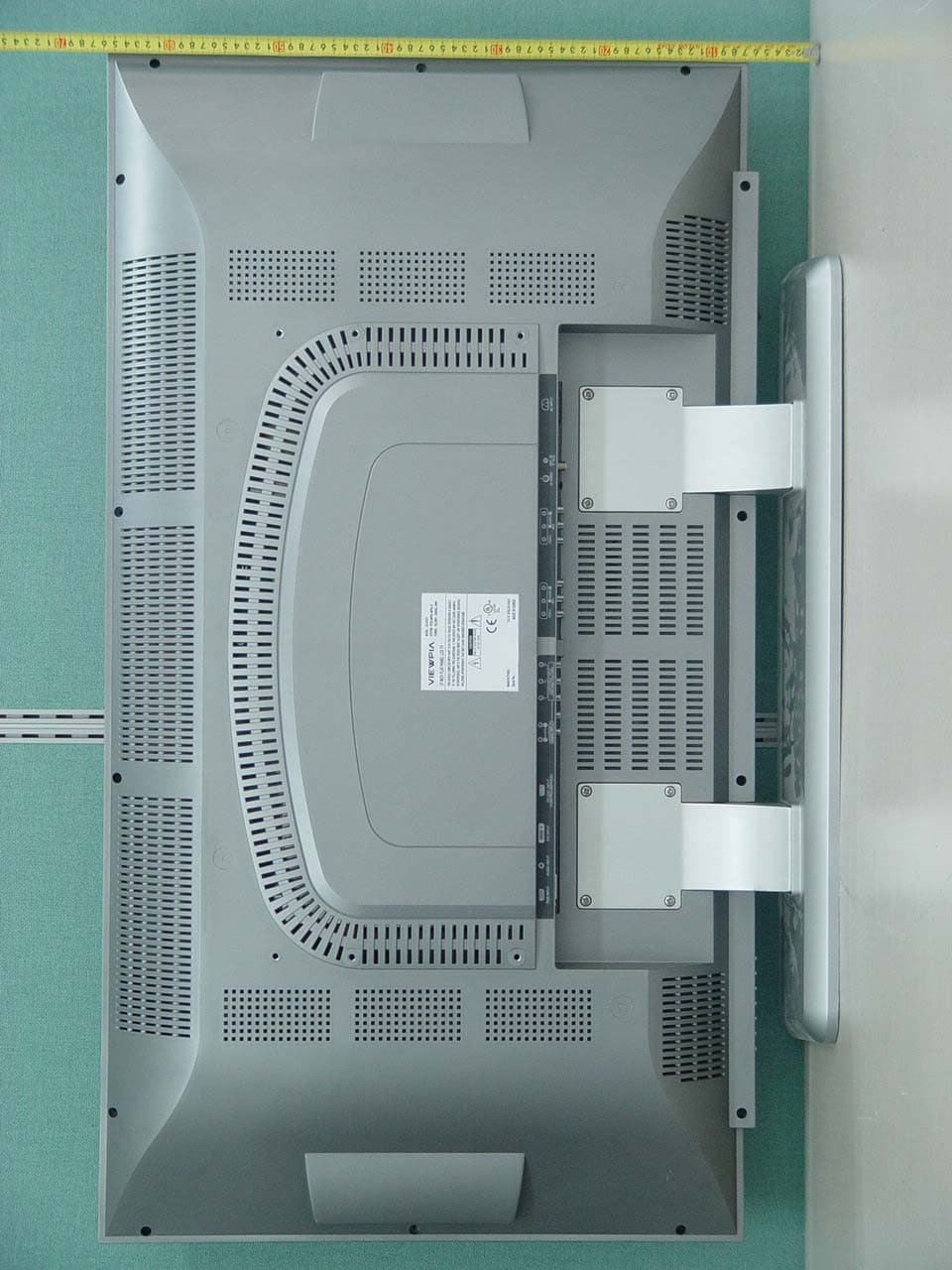
R7DLCD-37IU11
Jun 19, 200537 LCD TV/MONITOR
Equipment Class
JBP - Part 15 Class B Computing Device Peripheral
R7DLCD-42IU11
Jun 19, 200542" LCD TV/MONITOR
Equipment Class
JBP - Part 15 Class B Computing Device Peripheral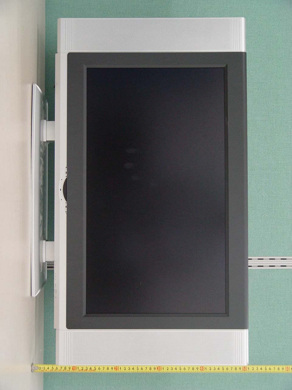
R7DLCD-26IU11
Jun 16, 200526" LCD TV/MONITOR
Equipment Class
JBP - Part 15 Class B Computing Device Peripheral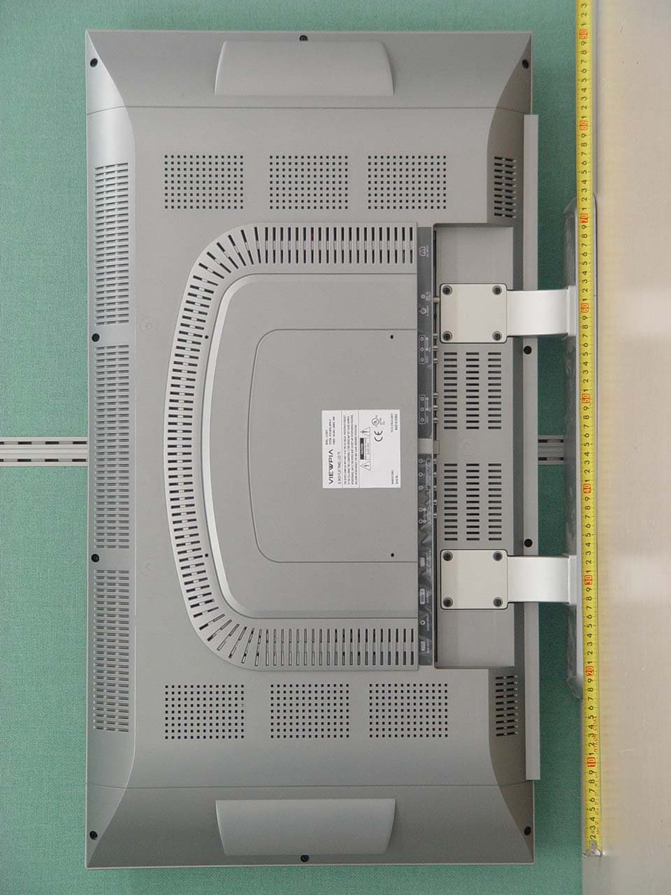
R7DLCD-32IU11
Jun 16, 200532" LCD TV/ Monitor
Equipment Class
JBP - Part 15 Class B Computing Device Peripheral