R7H-BKLINK-RAUDIO LINK SYSTEM
The Guitammer Company Inc.
Click to zoom
Application Details
- Equipment Class
- CYY - Communications Receiver used w/Pt 15 Transmitter
- Date of Grant
- Sep 23, 2004
- Application Purpose
- Original Equipment
- Date of Application
- Sep 23, 2004
- Equipment Note
- AUDIO LINK SYSTEM
- Frequency Range
- 907.00000000 - 925.00000000
- Company
- The Guitammer Company Inc.
- Country
- United States
Documents & Files
Document Text
Text extracted from the exhibit documents filed with the FCC. Open a document above to read the original.
Users Manual
GUITAMMER COMPANY, INC. WIRELESS LINK SYSTEM Transmitter setup (R7H-BKLINK-S) 1. Plug the sub-woofer (.1) audio output to the RCA jack in the back of the transmitter. 2. Plug the ac adapter into the wall outlet. Plug the jack end into the back of the transmitter. This powers the unit. 3. With normal volumes set, adjust the potentiometer to where the red light just starts to blink. This sets the radio link gain below clipping. Should another source cause the red light to stay on the potentiometer must readjusted. Receiver setup (R7H-BKLINK-R) 1. Plug one end of the RCA audio cord to the amplifier input. Plug the other end into the back of the receiver. 2. Plug the ac adapter into the wall outlet. Plug the jack end into the receiver. This powers the unit. 3. Note: For most installations the placement of the receiver and transmitter are not critical. For distances of more than 30 feet the units must not be block by metal objects. Also the units should face each other (the power lights have line of sight). FCC Notice applies to both the transmitter and receiver This device complies with Part 15 of the FCC Rules. Operation is subject to the following two conditions: (1) this device may not cause harmful interference, and (2) this device must accept any interference received, including interference that may cause undesired operation. Note: THE MANUFACTURER IS NOT REPONSIBLE FOR ANY RADIO OR TV INTERFERNCE CAUSED BY UNAUTHERIZED MODIFICATIONS TO THIS EQUIPMENT. SUCH MODIFICATIONS COULD VOID USER’S AUTHORITY TO OPERATE THE EQUIPMENT.
Block Diagram
9V AC Adapter 5V Regulator T5761Recv. IC Crystal Oscillator 7.08398 MHz ATTINYMCU Output Network 4th Order Low Pass Crystal Oscillator 7.15128 MHz Crystal Oscillator 7.21679 MHz R7H-BKLINK-R (Receiver) 5V
External Photos
External Photos, Label Placement
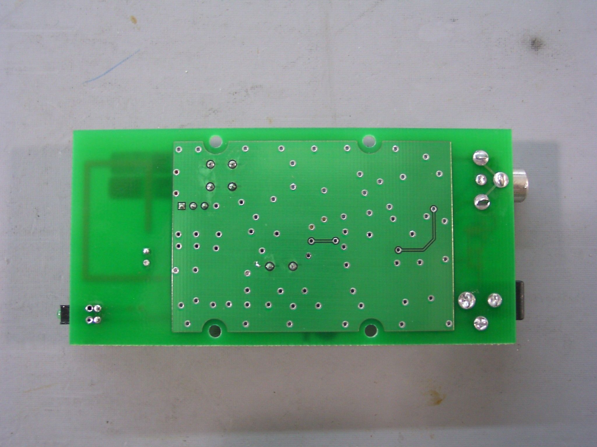
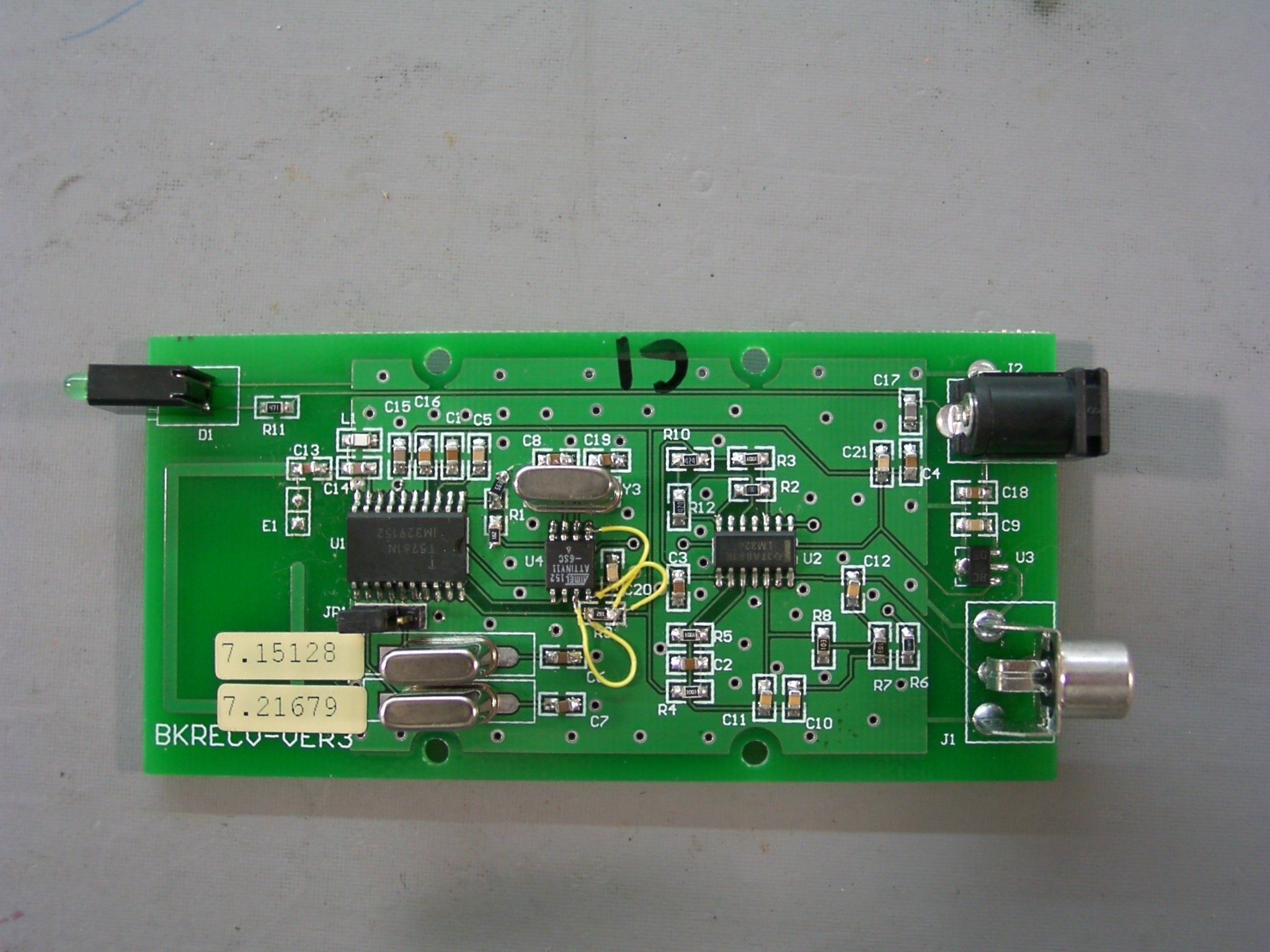
Internal Photos
Conducted Emissions Test Set-Up Close Up of Receiver Board Pictorial 2 R7H-BKLINK-R Conducted Set-Up and Close Up
Test Report
SMITH ELECTRONICS, INC. ELECTROMAGNETIC COMPATIBILITY LABORATORIES RADIO-FREQUENCY EMISSIONS TEST REPORT FOR AVCOM SMT, INC Receiver Model R7H-BKLINK-R September 21, 2004 Prepared by:___________________________ James R. Pollock Prepared for:Avcom SMT, Inc. 213 East Broadway Westerville, OH 43081 Smith Electronics, Inc. 8200 Snowville Road Brecksville, OH 44141 Phone: (440) 526-4386 Fax: (440) 526-9205 TABLE OF CONTENTS Certificate of Compliance.............................................................3 Objective...............................................................................4 Summary...............................................................................4 Test Information.......................................................................5 Introduction............................................................................6 Radiated Emissions Measurements..................................................6 Conducted Emissions Measurements...............................................7 Conclusions.............................................................................7 Method of Calculation.................................................................8 Sample Calculation.....................................................................8 Table 1 908 MHz Emissions.........................................................9 Table 2 916 Lo MHz Emissions......................................................10 Table 3 916 Hi MHz Emissions......................................................11 Table 4 925 MHz Emissions..........................................................12 Table 5 Nominal vs. Actual Frequency.............................................13 Pictorial 1 Test Set-Up................................................................14 Pictorial 2 Conducted Set-Up and Close-up of Receiver.........................15 Radiated Emissions Plots.............................................................16 Conducted Emissions Plots..........................................................17 CERTIFICATE OF COMPLIANCE 1.Manufacturer:Avcom SMT, Inc. 213 East Broadway Westerville, OH 43081 2.Contact:Paul H. Wiese Avcom SMT, Inc. 614/882-8176 3.Regulation:CFR47 – Part 15 15.107, 15.109 4.Measurement Method:ANSI C63.4-1992 5.EUT:Receiver Model R7H-BKLINK-R 6.Type:Wireless Audio Link Receiver 7.Tuned Frequencies907.744 MHz, 916.36352 MHz, 924.7488 MHz 8.Test Dates:June 15 – 17, 2004 9.Test LocationSmith Electronics, Inc. Test Lab and Open Field Site 8200 Snowville Rd. Brecksville, OH 10.Statement of Compliance: I hereby certify that measurements of radio frequency emissions from the Avcom SMT, Inc. Model R7H-BKLINK-R wireless link receiver were performed by me on June 15 to 17, 2004, and that the results of the measurements confirmed that the unit tested is capable of compliance with the above regulation. September 21, 2004 _____________________________________ DateJames R. Pollock, President Smith Electronics, Inc. RADIO FREQUENCY EMISSION MEASUREMENTS OBJECTIVE: The receiver emissions were measured in order to show that the emissions from the receivers were within the requirements of FCC Parts 15.107 and 15.109 for equipment of this type. SUMMARY The prototype of the Avcom SMT, Inc. Model R7H-BKLINK-R wireless link receiver has been shown to be capable of complying with those requirements of the Federal Communications Commission for an intentional radiator under Parts 15.107 and 15.109. All measured radiated emissions appear to be more than 17 dB below the 15.109 limits. The conducted measurements were also well suppressed, being about 10 dB or more below the new 15.107 limits. As the antenna is part of the circuit board and no provision for an external antenna is available, Part 15.111 measurements were not performed. TEST INFORMATION EQUIPMENT UNDER TEST Model R7H BKLINK-R Wireless Audio Link Receiver MANUFACTURER Avcom SMT, Inc. 213 East Broadway Westerville, OH 43081 TEST DATES June 15 – 17, 2004 TEST LABORATORY Smith Electronics, Inc. 8200 Snowville Rd. Brecksville, OH 44141 (440)526-4386 MEASUREMENT EQUIPMENT Hewlett-Packard Spectrum Analyzer 8568B with: 85650A RF Section S/N 2216A02120 85662A Display Section S/N 2152A03686 85650A Quasi-Peak Adapter S/N 2043A00350 Calibrated July, 2004 Hewlett Packard Spectrum Analyzer Model 8503EM S/N 3536A00147 Calibrated January, 2004 Singer Instrumentation EMI Receiver SN: 0366-06168 Calibrated June, 2003 ANTENNAS EMCO Biconical Model 3104 Frequency Range 20 – 200 MHz EMCO Log-Periodic Model 3146 Frequency Range 200 – 1000 MHz Stoddart Tuned Dipole Model 91598-2 Frequency Range 400 – 1000 MHz EMCO Double Ridged Guide Horn Model 3115 Frequency Range 1 – 18 GHz MISCELLANEOUS Hewlett-Packard Preamplifier Model 8447D S/N 1937A03103 12.2 m RG-214/U coaxial cable 0.6 m RG-214/U coaxial cable TEST REPORT INTRODUCTION The Model R7H-BKLINK-R receiver (EUT), manufactured by Avcom SMT, Inc. (Avcom) is part of a system specifically designed for receiving the short-range transmissions of audio signals from a companion transmitter. The audio is transmitted using pulse-width modulation and picked up by the receiver to be fed to a powered remote speaker. The R7H-BKLINK-R will be produced in two configurations. Each configuration can be set to receive on one of two frequencies. Each configuration will receive at a frequency of 916,36352 MHz. Additionally, one configuration will also receive at 907.744 MHz and the other at about 924.7488 MHz. This report indicates that the emissions of each configuration are within the limits set by 15.107 and 15.109. RADIATED EMISSIONS Field strength measurements were performed on the prototype receiver to assure that the radiated emissions were capable of compliance with the requirements of 15.109. As the LO emissions could not be detected at the three meter test distance, the receiver was moved to a 1 meter distance. The LO emissions were measured using the Singer receiver and the tuned di…
Text truncated - open the document above for the full version.
Test Setup Photos
Pictorial 1 R7H-BKLINK-R Radiated Emissions Test Set-up Conducted Emissions Test Set-Up Close Up of Receiver Board Pictorial 2 R7H-BKLINK-R Conducted Set-Up and Close Up
Contact Information
Applicant
Mark A. Luden
Test Firm
Smith Electronics, Inc.James Pollock
Technical Specifications
| # | Rule Parts | Frequency Range | Power Output |
|---|---|---|---|
| 1 | 15B | 907 MHz - 925 MHz | - |