R7K72018PI1Remote Control Transmitter
Gemini Trading s.r.l.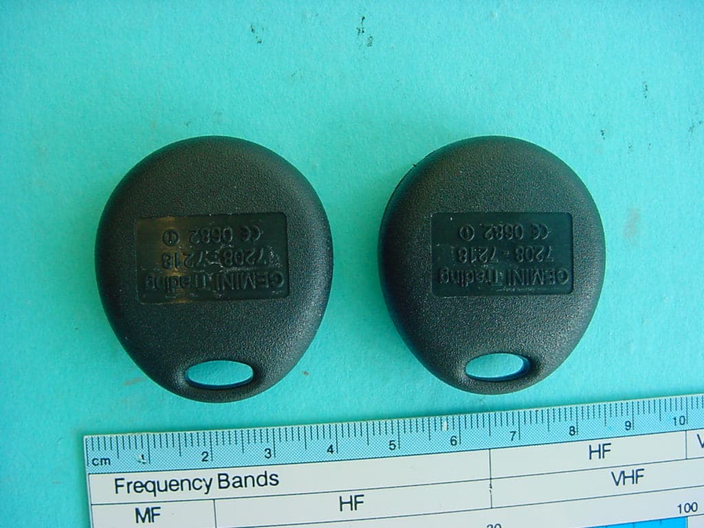
Click to zoom
Application Details
- Equipment Class
- DSC - Part 15 Security/Remote Control Transmitter
- Date of Grant
- Jun 29, 2004
- Application Purpose
- Original Equipment
- Date of Application
- Jun 29, 2004
- Equipment Note
- Remote Control Transmitter
- Frequency Range
- 433.92000000 - 433.92000000
- Company
- Gemini Trading s.r.l.
- Country
- Italy
Documents & Files
Document Text
Text extracted from the exhibit documents filed with the FCC. Open a document above to read the original.
Users Manual
CAUTIONCAUTION This device complies with Part 15 of the FCC Rules and with RSS-210 of Industry Canada.Operation is subject to the following two conditions: this device may not cause harmful interference this device must accept an y interference received, including interference that may cause undesired operation. This equipment has been tested and found to comply with the limits for a Class B di g ital device, pursuant to Part 15 of the FCC Rules. These limits are designed to provide reasonable protection against harmful interference in a residential installation. This equipment g enerates, uses and can radiate radio frequenc y energy and, if not installed and used in accordance with the instructions, may cause harmful interference to radio communications. However, there is no g uarantee that interference will not occur in a particular installation. If this equipment does cause harmful interference to radio or television reception, which can be determined by turning the equipment off and on, the user is encoura g ed to tr y to correct the interference by one or more of the following measures: Reorient or relocate the receiving antenna.Increase the separation between the equipment and receiver.Connect the equipment into an outlet on a circuit different from that to which the receiver is connected.Consult the dealer or an experienced radio/TV technician for help. DD DDDD WARNING Chan g es or modifications made to this equipment not expressl y approved b y ma y void the FCC authorization to operate this equipment. GEMINI TRADING srl TRANSMITTER TECHNICAL DATA Battery nominal voltage 2x3V CR1616 Lithium Battery Frequency 433.92 Mhz Aerial Loop integrated on PCB
Users Manual
I marchi sono di proprietà della PIAGGIO & C S.p.a. www.piaggio.com V.le R. Piaggio, 25 - 56025 PONTEDERA (PI) ORIGINAL ACCESSORIES MANUALE DI INSTALLAZIONE PER CENTRALINA APRISELLA E BAULETTO PIAGGIO X8 ORIGINAL ACCESSORIES GB F D I NL GR E INTRODUZIONE PIAGGIO si congratula con Voi per aver scelto un accessorio originale e vi invita a leggere attentamente il contenuto di questo manuale di istruzioni. AVVERTENZE: !Questo manuale, contiene preziosi consigli per poter eseguire una installazione “a regola d’arte”. Vi preghiamo quindi, di leggerlo in ogni sua parte. !Ricordate che, al fine dell’ottenimento di un buon risultato, ogni fase di installazione del sistema ricopre un’importanza fondamentale. E’ quindi necessario, non trascurare alcun dettaglio durante questa operazione . !Tutte le informazioni presenti in questo manuale, fanno riferimento unicamente alle caratteristiche tecniche del sistema PIAGGIO. !Tutte le informazioni e le caratteristiche riportate sul presente manuale, sono attuali al momento della stampa. PIAGGIO si riserva il diritto di effettuare modifiche in qualunque momento senza preavviso. INDICE Indice Introduzione Smontaggio delle fiancate laterali Fissaggio e connessione elettrica della centralina aprisella Collaudo del dispositivo Funzioni di supporto e manutenzione 2 3 4 6 7 8 SMONTAGGIO DELLE FIANCATE LATERALI Procedere come segue uRimuovere la maniglia passeggero agendo sulle viti superiori “A” e sulle inferiori “B” situate nel vano sottosella. vRimuovere le due viti superiori “C” di fissaggio delle fiancate laterali. wRimuovere il fanalino posteriore agendo sulle due viti di fissaggio “D”, per poter accedere alla vite di fissaggio dell’indicatore di direzione “I” e rimuoverla. xRimuovere la vite “E” della fiancata laterale posta sotto l’indicatore di direzione yRimuovere le quattro viti laterali “F” zRimuovere le due viti “G” e quindi l’elemento centrale di uniome fiancate (scollegando il connettore luce targa), per permettere la rimozione dei due fissaggi sottostanti “H”. 1 2 45 3 6 FISSAGGIO E CONNESSIONE ELETTRICA DELLA CENTRALINA APRISELLA COLLAUDO DEL DISPOSITIVO FUNZIONI DI SUPPORTO E MANUTENZIONE Procedere come segue Memorizzazione di nuovi telecomandi uUna volta rimossa la fiancata posteriore sinistra, individuare i prigionieri “A” da utilizzare per il fissaggio della centralina ed il connettore “B” da utilizzare per la connessione della centralina all’impianto elettrico del veicolo . vPosizionare la centralina nella propria sede facendo combaciare le due asole ai prigionieri “A”. Collegare infine, la centralina aprisella all’impianto elettrico del veicolo utilizzando il connettore”B” precedentemente individuato. wAssicurare la centralina ai prigionieri utilizzando due dadi di 5mm.Ø uPremere brevemente il pulsante puntinato del telecomando, l’eletroserratura della sella si azionerà provocandone lo sbloccaggio. vPremere brevemente il pulsante liscio del telecomando, l’elettroserratura del bauletto posteriore si azionerà provocandone lo sbloccaggio. Il dispositivo viene fornito con un telecomando in dotazione. Se il cliente lo desidera, è possibile aggiungere al sistema altri telecomandi (per un massimo di 7). Per eseguire la procedura di memorizzazione, procedere come descritto di seguito: uInserire e disinserire in sequenza per cinque volte, il quadro d’accensione. IMPORTANTE: ?Eseguire questa operazione piuttosto lentamente. ?Alla quinta volta, il quadro d’accensione deve essere lasciato inserito. vPremere uno dei pulsanti del telecomando da memorizzare. wLa centralina confermerà l’avvenuta memorizzazione azionando una delle due elettroserrature. 12 INTRODUCTION WARNING: Piaggio congratulates you for choosing an original accessory and invites you to read the contents of this instruction manual carefully. !The manual contains precious advice that will help you install this alarm in the best possible way. Please take time to read all of the instructions thoroughly. !Remember, for good results, each step of the installation of the system is very important. Therefore, do not neglect any detail during this operation !The information in this handbook refers exclusively to the technical characteristics of the PIAGGIO System. All the information and characteristics reported in this manual are current at the moment of printing. PIAGGIO reserves the right to make alterations at any time without prior notification ! CONTENTS Contents Introduction Removing the sides panels Fastening the saddle-lock control box, and the electrical connections Testing the unit Support and maintenance functions 2 3 4 6 7 7 UK REMOVING THE SIDES PANELS Proceed as follows uRemove the pillion handle by loosening the two top, “A”, and two bottom, “B”, fixing screws inside the helmet compartment. vLoosen the two side-fairing fixing screws, “C”. wRemoving the taillight by loosening the two screws, “D”, in order to access, and remove, the turn signal light fixing screw, “I”. xLoosen the side-fairing screw, “E”, underneath the turn signal light. yRemove the four side screws, “F” zloosen the two screws, “G”, and hence remove the fairing mid-joining segment (detaching the license plate lamp connector),in order to allow for the removal of the under-lying fixings, “H”. 1 2 45 3 6 FASTENING THE SADDLE-OPENING CONTROL BOX AND ELECTRICAL CONNECTIONS TESTING THE SYSTEM SUPPORT AND MAINTENANCE FUNCTIONS Memorising new remote controls u w . x. After removing the rear left side panel, locate the stud bolts “A”, that will be used to fasten the control box in place, and the connector “B”, that will be used to connect the control box to the vehicle electric system. vFit the control box into its seat matching the two slots with the stud bolts “A”. Finally, connect the control box to the vehicle electrical system using the connector “B” identified above. Fasten the control box on the stud bolts with two Ø 5 mm. Nuts uBriefly press the dotted button on the remote control. The electric lock of the saddle will…
Text truncated - open the document above for the full version.
Cover Letter(s)
GEMINI TRADING s.r.l. - Via Luigi Galvani, 12 21020 Bodio Lomnago VARESE – ITALY Tel. (+39) 0332943211 Fax (+39) 0332948080 www.gemini-alarm.com e-mail: [email protected] P.I. 02015520121 – C.F. 00820650125 Capitale sociale € 93.600 Iscrizione Tribunale di Varese Nr. 18713 C.C.I.A.A. Nr. 203197 – Nr. MECC. VA040645 ALARM SYSTEMS CONFIDENTIALITY REQUEST Federal Communication Commission Equipment Authorization Division, Application Processing Branch 7435 Oakland Mills Road Columbia, MD 21048 June 22, 2004 TO WHOM IT MAY CONCERN Pursuant to Paragraphs §0.457 and 0.459 of the Commission’s Rules (47 C.F.R.) and Section §552(b)(4) of the Freedom of Information Act, Company requests confidentiality for the following products: FCC ID Number Product Title/Model R7K72018PI1 GEMINI 7553PI – 7551PI – 7539PI3 – 7208E – 7218E For the product stated above, we request that the following information be held confidential: 1. Circuit diagrams, BOM, and PCBs submitted as Equipment Authorization Electronic Filing attachment: "schematics”. 2. Block diagram submitted as Equipment Authorization Electronic Filing attachment: “blockdiagram”. 3. Operational description submitted as Equipment Authorization Electronic Filing attachment: “operational description” The above exhibits contain Company trade secrets and proprietary information that could be of benefit to our competitors regarding the design of our mobile handset. This material is not customarily available to the general public and we request that it be withheld from public inspection. If you have any questions, please feel free to contact me at the address shown below. Sincerely, Name: Andrea Rossi Company: Gemini Trading s.r.l. Address: Via Luigi Galvani, 12 21020 Bodio Lomnago (Va) Italy Phone: +39 0332 943211 Email: [email protected]
External Photos
CETECOM ICT Services GmbH Test report No.: 2-3610-01-02/04 Date: 2004-05-27 Page 23 (26) Photographs of the equipment Photograph no.: 1 CETECOM ICT Services GmbH Test report No.: 2-3610-01-02/04 Date: 2004-05-27 Page 24 (26) Photographs of the equipment Photograph no.: 2
ID Label/Location Info
SPECIFICHE CLICHE BICOLORE PIAGGIO - 7208PI1 -7218PI1 FCC ALARM SYSTEMS Data Materiale clichè File Name CL1546. CDR 29/06/04 Rev. 01 CL1546 N. DIS. CL1546-00 Codice Gemini SCALA 1:1 ACCIAIO 80 x 80mm 7208PI1 - 7218PI1 FCC ID: R7K72018PI1 GEMINI Trading s.r.l. 1 0 1 2 . 5 1 . 7 1 . 5 1 . 5 2 2 3 . 2 m m 3 1 . 5 1 . 5 3 7208PI1 - 7218PI1 FCC ID: R7K72018PI1 GEMINI Trading s.r.l. 7208PI1 - 7218PI1 FCC ID: R7K72018PI1 GEMINI Trading s.r.l. ACCIAIO 80 x 80mm Data Materiale clichè File Name CL1546 . CDR 29/06/04 Rev. 01 N. DIS. P0SCL1546-00 CL1546 Codice Gemini SPECIFICHE DI POSIZIONAMENTO 7208PI1 - 7218PI1 FCC ID: R7K72018PI1 GEMINI Trading s.r.l. ALARM SYSTEMS
Internal Photos
CETECOM ICT Services GmbH Test report No.: 2-3610-01-02/04 Date: 2004-05-27 Page 25 (26) Photographs of the equipment Photograph no.: 3 CETECOM ICT Services GmbH Test report No.: 2-3610-01-02/04 Date: 2004-05-27 Page 26 (26) Photographs of the equipment Photograph no.: 4
Test Report
CETECOM ICT Services GmbH Radio Satellite Communication Untertürkheimer Straße 6–10, D-66117 Saarbrücken, Telephone +49 (0) 681 598- 0, Fax +49 (0) 598 9075 Test report No.: 2-3610-01-02/04 This test report consists of 27 pages Page 1 (26) Recognized by the Federal Communications Commission Anechoic chamber registration no.: 90462 (FCC) Anechoic chamber registration no.: 3463 (IC) TCB ID: DE 0001 Accredited by the German Accreditation Council DAR–Registration Number TTI–P–G 081/94-D0 Independent ETSI compliance test house ETSI Accredited Bluetooth™ Test Facility (BQTF) Test report No. :2-3610-01-02/04 Standard :Part 15.231 Applicant :Gemini Trading s.l.r. Type :7218PI1 / 7208PI1 FCC–ID No : R7K72018PI1 BLUETOOTH is a trademark owned by Bluetooth SIG, Inc. and licensed to CETECOM CETECOM ICT Services GmbH Test report No.: 2-3610-01-02/04 Date: 2004-05-27 Page 2 (26) Table of contents 1 General information 1.1 Notes 1.2 Testing laboratory 1.3 Details of applicant 1.4 Application details 1.5 Test item 1.6 Test specifications 2 Technical test 2.1 Summary of test results 2.2 Test report CETECOM ICT Services GmbH Test report No.: 2-3610-01-02/04 Date: 2004-05-27 Page 3 (26) 1 General information 1.1 Notes The test results of this test report relate exclusively to the test item specified in 1.5. The CETECOM ICT Services GmbH does not assume responsibility for any conclusions and generalisations drawn from the test results with regard to other specimens or samples of the type of the equipment represented by the test item. The test report may only be reproduced or published in full. Reproduction or publication of extracts from the report requires the prior written approval of the CETECOM ICT Services GmbH. Test laboratory manager: 2004-05-28 RSC - 8411 Berg M. Date Section Name Signature Technical responsibility for area of testing: 2004-05-28 RSC - 8412 Hausknecht D. Date Section Name Signature CETECOM ICT Services GmbH Test report No.: 2-3610-01-02/04 Date: 2004-05-27 Page 4 (26) 1.2 Testing laboratory CETECOM ICT Services GmbH Untertürkheimer Straße 6 - 10 66117 Saarbrücken Germany Telephone : + 49 681 598 - 0 Telefax : + 49 681 598 - 9075 E-mail : [email protected] Internet : www.cetecom-ict.de Accredited testing laboratory The test laboratory (area of testing) is accredited according to DIN EN ISO/IEC 17025. DAR registration number: TTI-P-G-081/94-D0 Listed by: Federal Communications Commission (FCC) Identification/Registration No: 90462 Anechoic chamber registration no.:3463 (IC) Accredited Bluetooth TM Test Facility (BQTF) BLUETOOTH TM is a trademark owned by Bluetooth SIG, Inc. and licensed to CETECOM 1.3 Details of applicant Name : Gemini Trading s.l.r. Street : Via Galvani 12 City : I-21020 Bodio Lomnago Country : Italy Telephone: +39 0332 943211 Fax : +39 0332 9438080 E-mail : [email protected] Contact person: Name : Dr. Andrea Rossi Telephone : +39 0332 943211 Telex : +39 0332 9438080 E-mail : [email protected] 1.4 Application details Date of receipt of test item : 2004-04-22 Date of test : 2004-05-24 Person(s) who have been : - present during the test CETECOM ICT Services GmbH Test report No.: 2-3610-01-02/04 Date: 2004-05-27 Page 5 (26) 1.5 Test item Type of equipment : Remote Control Transmitter Type designation : 7218PI1 (handheld 1 button transmitter) 7208PI1 (handheld 2 buttons transmitter) Manufacturer : Same as applicant Street : City : Country : Serial number : - / - Additional information : Frequency : 433.92 MHz Type of modulation : 10K0A1D Channel spacing : >25 kHz Number of channels : 1 Antenna : Integral printed board antenna Max. ERP : Peak: 55.9 dBμV/m ; Average: 53.2 dBμV/m at 3m distance Power supply : 6.0 V DC by 2 x 3.0 VDC Lithium Batteries Temperature range : -10°C - +55°C FCC ID : R7K72018PI1 1.6 Test specifications: FCC Part 15 §15.209 FCC Part 15 §15.231 CANADA RSS-210 CETECOM ICT Services GmbH Test report No.: 2-3610-01-02/04 Date: 2004-05-27 Page 6 (26) 2 Technical test 2.1 Summary of test results The radiated measurements were performed vertical and horizontal over the whole frequency range. We start at 1 m high with vertical receiving antenna and rotate the dish continuously. During rotation we use the antenna lift system to vary the high from 1 to 4 m. So we find maximum radiation output. At this points we do manual re-measurements. After this we do the same measurements in horizontal position of the receiving antenna. This (horizontal and vertical) is made for all the three planes of the test sample. We use the maximum received results. The detector function and selection of bandwidth are according ANSI C63.2-1996 item 8.2.1 and ANSI C63.4-1992 Item 4.2. Antennas are conform with ANSI C63.2-1996 item 15. 150 kHz - 30 MHz: Quasi Peak measurement, 9kHz Bandwidth, passive loop antenna. 30 MHz - 200 MHz: Quasi Peak measurement, 120KHz Bandwidth, biconical antenna 200MHz - 1GHz: Quasi Peak measurement, 120KHz Bandwidth, log periodic antenna 1GHz: Average, RBW 1MHz, VBW 10 MHz, wave-guide horn All measurement settings are according to FCC 15.35, 15.205, 15.209,15.231. The product fulfills also the requirements for CANADA RSS-210 No deviations from the technical specification(s) were ascertained in the course of the tests performed. CETECOM ICT Services GmbH Test report No.: 2-3610-01-02/04 Date: 2004-05-27 Page 7 (26) 2.2 Test report TEST REPORT Test report no. : 2-3610-01-02/04 CETECOM ICT Services GmbH Test report No.: 2-3610-01-02/04 Date: 2004-05-27 Page 8 (26) TEST REPORT REFERENCE LIST OF MEASUREMENTS Paragraph PARAMETER TO BE MEASURED PAGE TRANSMITTER PARAMETERS § 15.231 (e) Timing of the transmitter 9 § 15.231 (e) Emission limitations 11 § 15.231 (c) Occupied bandwidth 15 Test equipment listing 19 Photographs of the equipment 21 CETECOM ICT Services GmbH Test report No.: 2-3610-01-02/04 Date: 2004-05-27 Page 9 (26) REFERENCE NUMBER(S) OF TEST EQUIPMENT USED : 17 - 24 (for reference numbers see test equipment listing) Timing of the transmit…
Text truncated - open the document above for the full version.
Test Setup Photos
CETECOM ICT Services GmbH Test report No.: 2-3610-01-02/04 Date: 2004-05-27 Page 21 (26) Test site CETECOM ICT Services GmbH Test report No.: 2-3610-01-02/04 Date: 2004-05-27 Page 22 (26) Test site
Contact Information
Applicant
Andrea Rossi(Dr.)
Test Firm
Cetecom ICT Services GmbHRalf Hoehn
Technical Specifications
| # | Rule Parts | Frequency Range | Power Output |
|---|---|---|---|
| 1 | 15.231 | 433.92 MHz - 433.92 MHz | - |