R7L-645-EJBActive RF ID Tag
E. J. Brooks Company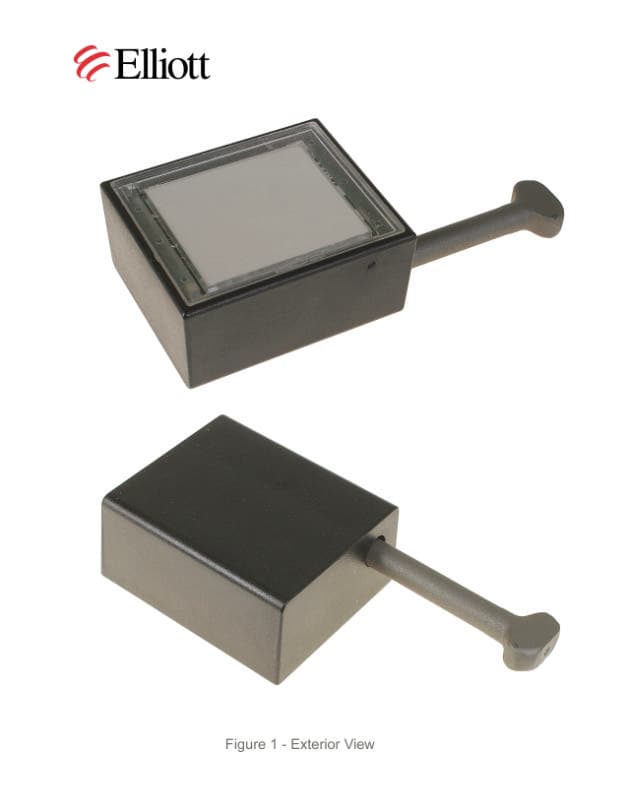
Click to zoom
Application Details
- Equipment Class
- DSR - Part 15 Remote Control/Security Device Transceiver
- Date of Grant
- Aug 02, 2004
- Application Purpose
- Original Equipment
- Date of Application
- Aug 02, 2004
- Equipment Note
- Active RF ID Tag
- Frequency Range
- 433.92000000 - 433.92000000
- Company
- E. J. Brooks Company
- Country
- United States
Documents & Files
Document Text
Text extracted from the exhibit documents filed with the FCC. Open a document above to read the original.
Users Manual
Installation Guide For EJ Brooks Bolt Seal EJ-645-21 Installation Guide Number Page 1 of 3 pages ELECTRONIC COPY WT6 704 001 NOT CONTROLLED IF PRINTED Date Prepared Revision Revision Date Revision Approval July 2, 2004 Prepared By Approved By John G. De Marco B. Debrody EJ-645-1 User Manual.doc EJ Brooks Bolt Seal EJ-645-21 Installation Guide The EJ Brooks Single-Use Electronic Bolt Seal EJ-645-21 consists of a printed circuit board incorporating a non-replaceable battery enclosed in a sealed plastic case with a fixed bolt designed for single insertion. Once the bolt is inserted in the housing, it is locked in place, and cannot be removed without destroying the unit. • The EJ Brooks EJ-645-21 tag contains a label on the front with the tag serial number in both bar code and numerical format and includes the product model number. The tag also includes a label on the back, which contains the FCC compliance markings. • The EJ Brooks EJ-645-21 tag can be exposed to environments including rain, snow, and direct exposure to sunlight. Installation Guide For EJ Brooks Bolt Seal EJ-645-21 Installation Guide Number Page 2 of 3 pages ELECTRONIC COPY WT6 704 001 NOT CONTROLLED IF PRINTED Date Prepared Revision Revision Date Revision Approval July 2, 2004 Prepared By Approved By John G. De Marco B. Debrody EJ-645-1 User Manual.doc • The tag battery life is a minimum of 3 months under normal operating conditions. The tag contains an internal lithium battery and should be discarded according to local safety requirements. Tag Attachment Do not insert the bolt through the body of the tag housing prior to inserting it through the security hasp. Once the internal bushing is joined to the bolt, it cannot be removed without destroying the housing. The EJ Brooks EJ-645-21 contains an integrated locking bolt assembly. 1. Place the bolt through the lock holes of the closed security hasp. • You can orient the tag with the main tag body either below (recommended) or above the container hasp. 2. Snap the bolt into the seal housing far enough to hear an audible ‘click’, locking the bolt into place, where the bolt is pushed in all the way. To make sure the bolt is secure, pull on the seal case housing gently to make sure the bolt is secure. The bolt is now secured via the unit’s internal bushing. Installation Guide For EJ Brooks Bolt Seal EJ-645-21 Installation Guide Number Page 3 of 3 pages ELECTRONIC COPY WT6 704 001 NOT CONTROLLED IF PRINTED Date Prepared Revision Revision Date Revision Approval July 2, 2004 Prepared By Approved By John G. De Marco B. Debrody EJ-645-1 User Manual.doc Tag Operation • After installation you may communicate with the device and monitor events using the appropriate commands from a Savi Mobile Readers SMR-640/650 or Fixed Readers SR-640 or 650. • If the bolt is removed, a tamper event will occur.
Attestation Statements
Keep This Document E.J. Brooks Company, EJ-645-21 Compliance Notice Federal Communication Commission (FCC) Notice The Federal Communications Commission has established technical standards regarding radio frequency energy emitted by computer devices. This equipment has been tested and found to comply with the limits for a Class A digital device, pursuant to Part 15 of the FCC Rules. These limits are designed to provide reasonable protection against harmful interference when the equipment is operated in a commercial environment. This equipment generates, uses, and can radiate radio frequency energy and, if not installed and used in accordance with the instruction manual, may cause harmful interference with radio/TV reception. Operation of this equipment in a residential area is likely to cause harmful interference in which case the user will be required to correct the interference at his own expense. Changes or modifications to this equipment that are not expressly approved by E.J. Brooks Company could void the warranty and the authority to operate this equipment. E.J. Brooks Company is not responsible for radio/TV interference caused by using unauthorized cable or by making unauthorized changes to this equipment. E.J. Brooks Company 8 Microlab Road Livingston, New Jersey 07036 Phone: (973) 597-2900 Fax: (973) 597-2919 Web site: www.ejbrooks.com Copyright©2004, E.J. Brooks Company. All rights reserved. First edition dated June 2004. Federal Communication Commission (FCC) Label Statement This device complies with Part 15 of the FCC Rules. Operation is subject to the following conditions: ♦ This device may not cause harmful interference, and ♦ This device must accept any interference received, including interference that may cause undesired operation. The label statement corresponds to the following devices: Devices Model FCC ID Radio Tag EJ-645-21 R7L-645-EJB Declaration of Conformity Hereby, E.J. Brooks Company, 8 Microlab Road, Livingston, NJ 07036 Declares that E.J. Brooks EJ-645-21 are in compliance with the essential requirements and other relevant provisions of Directive 1999/5/EC Authorized for use in: Austria, Belgium, Denmark, Finland, France, Germany, Greece, Ireland, Ireland, Italy, Luxembourg, Netherlands, Norway Portugal, Spain, Sweden, Switzerland, & United Kingdom. Keep This Document English Hereby, E.J. Brooks Company, declares that this EJ-645- 21 is in compliance with the essential requirements and other relevant provisions of Directive 1999/5/EC. Finnish E.J. Brooks Company, vakuutta täten että EJ-645-21 tyyppinen laite on drektiivin 1999/5/EY Oleellisten vaatimusten ja sitä koskevien direktiivin muiden ehtojen mukainen. Dutch Hierbij verklaart E.J. Brooks Company, declare que l’appareil EJ-645-21 est conforme aux exigences essentielles et aux atres dispositions pertinentes de la directive 1999/5/CE French Par la présente E.J. Brooks Company, déclare que ce EJ- 645-21 est conforme aux exigences Essentielles et aux autes dispositions de laa directive 199/5/CE qui lui sont appicables Swedish Härmed intygar E.J. Brooks Company att denna EJ-645-21 står I överensstämmeelse med de väsentliga egenskapskrav och övriga relevanta bestämmelser som framgår av direktiv 1999/5/EG. Danish Undertegnede E.J. Brooks Company, erklærer herved, at følgende udstyr EJ-645-21 overholder de væsentlige krav og øvrige relevante krav I direktiv 1999/5/EF German Hiermit erklärt E.J. Brooks Company, dass sich dieser/diese/dieses EJ-645-21 in Übereinstimmung mit den grundlegenden Anforderungen und den anderen relevanten Vorschriften der Richtlinie 1999/5/EG benfindet” . (BMWi) Hiermit erklärt E.J. Brooks Company, die Übereinstimmung des Gerätes EJ-645-21 mit den grundlegenden Anforderungen und den anderen relevanten Vorschriften der Richtlinie 1999/5/EG. (Wien) Italian Con la presente E.J. Brooks Company, dichiara che questo EJ-645-21 è conforme ai requisiti essenziali ed alle altre disposizioni perienenti stabilite dalla direttiva 1999/e/CE. Spanish Por medio de la presente E.J. Brooks Company, declara que lel EJ-645-21 cumple con los requisitos esenciales y cualesquiera otras disposiciones aplicables o exigibles de la Directiva 1999/5CE Portuguese E.J. Brooks Company, declara que este EJ-645-21 está conforme com os requisitos essenciais e outras disposicões da Directiva 1999/5/CE
Cover Letter(s)
File: R55977 June 15, 2004 American TCB 6731 Whittier Avenue, Suite C110 McLean, VA. 22101 Gentlemen: The enclosed documents constitute a formal submittal and application for a Grant of Equipment Authorization pursuant to Subpart C of Part 15 of FCC Rules (CFR 47) regarding intentional radiators. Data within this report demonstrates that the equipment tested complies with the FCC limits for intentional radiators. Elliott Laboratories, as duly authorized agent prepared this submittal. A copy of the letter of our appointment as agent is enclosed. If there are any questions or if further information is needed, please contact Elliott Laboratories for assistance. Sincerely, Mark Briggs Vice President of Engineering MB/dmg Enclosures: Agent Authorization Letter Emissions Test Report with Exhibits
External Photos
External Photograph
ID Label/Location Info
6 5 4 2 1 JGD JGD N/A JGD 7/6/04 N/A N/A N/A 2:1 NONE R4192000-1-C EXPLODED VIEW ELECTRONIC BOLT SEAL 3 7 ITEM NO. PART NUMBER DESCRIPTION QTY. 1 N/A HOUSING COVER 1 2 N/ALABEL 1 3 N/ALABEL PLATE 1 4 N/A PC BOARD1 5 N/A LOCKING NUT 1 6 N/A HOUSING 1 7N/A BOLT 1 ITEM NO. PART NUMBER DESCRIPTION QTY. 1 N/A HOUSING COVER 1 2 N/ALABEL 1 3 N/ALABEL PLATE 1 4 N/A PC BOARD1 5 N/A LOCKING NUT 1 6 N/A HOUSING 1 7N/A BOLT 1 DRAWN BY CHECKED BY CONCEPT BY APPROVED BY DESCRIPTION MATERIAL HT TREAT/COAT NEXT ASSEMBLY SCALE REVISION DRAWING # E.J. BROOKS CO. 1 BROOKS PLAZA NEWTON, NJ 07860 DATE TOLERANCES UNLESS OTHERWISE SPECIFIED ALL DIMENSIONS ARE IN US INCHES DECIMALS XX .01 XXX .005 XXXX .0005 FRACTIONS 1/64 ANGLES 0'-30 SYM CHANGE BY APPROVEDECR# DATE REVISION DESCRIPTION 1 2 34 567 89 10 11 1213141516 17 18 19 20 21 A B C D E F G H I J K L M N O P A B C D E F G H I J K L M N O P 1 2 3 456 78 9 10 11 1213 14 15 16 17 1819 20 21 CRITICAL DIMENSION MAXIMUM DIMENSION C M
Internal Photos
Internal Photographs
Test Report
File: R55977 Page 1 of 14 Electromagnetic Emissions Test Report and Application for Grant of Equipment Authorization pursuant to FCC Part 15, Subpart C Specifications for an Intentional Radiator and FCC Part 15, Subpart B Specifications for a Receiver on the EJ Brooks Company Model: EJ-645-21 FCC ID: R7L-645-EJB GRANTEE: EJ Brooks Company One Brooks Plaza Newton, NJ 07860 TEST SITE: Elliott Laboratories, Inc. 684 W. Maude Avenue Sunnyvale, CA 94086 REPORT DATE: June 15, 2004 FINAL TEST DATE: May 27, 2004 AUTHORIZED SIGNATORY: ______________________________ Mark Briggs Vice President of Engineering Elliott Laboratories, Inc. is accredited by the A2LA, certificate number 2016-01, to perform the test(s) listed in this report. This report shall not be reproduced, except in its entirety, without the written approval of Elliott Laboratories, Inc. Elliott Laboratories, Inc. -- EMC Department Test Report Report Date: June 15, 2004 File: R55977 Page 2 of 14 Pages TABLE OF CONTENTS COVER PAGE...................................................................................................................................................................................1 TABLE OF CONTENTS..............................................................................................................................................................2 SCOPE............................................................................................................................................................................................3 OBJECTIVE...................................................................................................................................................................................3 STATEMENT OF COMPLIANCE..............................................................................................................................................3 EMISSION TEST RESULTS.......................................................................................................................................................4 LIMITS OF CONDUCTED INTERFERENCE VOLTAGE.....................................................................................................4 LIMITS OF RADIATED FIELD STRENGTH - RECEIVER..................................................................................................4 BANDWIDTH............................................................................................................................................................................4 DUTY CYCLE CALCULATION..............................................................................................................................................4 PERIOD OF OPERATION........................................................................................................................................................4 LIMITS OF RADIATED FIELD STRENGTH –INTENTIONAL RADIATOR..................................................................5 MEASUREMENT UNCERTAINTIES....................................................................................................................................5 EQUIPMENT UNDER TEST (EUT) DETAILS..........................................................................................................................6 GENERAL...................................................................................................................................................................................6 ENCLOSURE..............................................................................................................................................................................6 SUPPORT EQUIPMENT...........................................................................................................................................................6 EXTERNAL I/O CABLING.......................................................................................................................................................6 EUT OPERATION.....................................................................................................................................................................6 TEST SITE......................................................................................................................................................................................7 GENERAL INFORMATION.....................................................................................................................................................7 CONDUCTED EMISSIONS CONSIDERATIONS.................................................................................................................7 RADIATED EMISSIONS CONSIDERATIONS....................................................................................................................7 MEASUREMENT INSTRUMENTATION..................................................................................................................................8 RECEIVER SYSTEM..................................................................................................................................................................8 INSTRUMENT CONTROL COMPUTER...............................................................................................................................8 LINE IMPEDANCE STABILIZATION NETWORK (LISN)................................................................................................8 FILTERS/ATTENUATORS......................................................................................................................................................9 ANTENNAS...............................................................................................................................................................................9 ANTENNA MAST AND EQUIPMENT TURNTABLE................................................................................…
Text truncated - open the document above for the full version.
Test Report
Note - the attached timing verification plots were taken on the Savi ST-64x series of tags. The EJ-64X series of RFID tags use an identical protocol and the same controlling firmware as the Savi ST-64x series. Timing Verification The following plots were made to demonstrate the timing of the transmissions from the Savi ST-60X and ST-64X series of tags. The actual tag used during testing was an ST-602, but both tag series use the same firmware. These plots are representative of the transmission timing for both the 640 and 604 series. The graphs show: A 10.1 second interval between successive transmissions; A total of four pulses per transmission, each pulse separated by a 90mS period, giving a total transmission time of 310mS; An individual pulse width of 10mS. The timing of the pulses meets the requirements of FCC 15.231(e) as the transmission time is less than 1 second and the silent period is greater than 30 times the duration of each transmission and greater than 10 seconds.
Test Setup Photos
Test Configuration Photos
Contact Information
Applicant
Robert F Debrody(Director of Engineering)
Technical Contact
Elliott Laboratories Inc.Mark Briggs
[email protected]408-245-7800
684 West Maude Ave. · Sunnyvale, California · United States
Test Firm
Element Materials Technology Fremont NewarkDavid Bare
Technical Specifications
| # | Rule Parts | Frequency Range | Power Output |
|---|---|---|---|
| 1 | 15.231(e) | 433.92 MHz - 433.92 MHz | - |