R94072004FSK Transmitter
Metrics Technology, Inc. DBA CasaWorks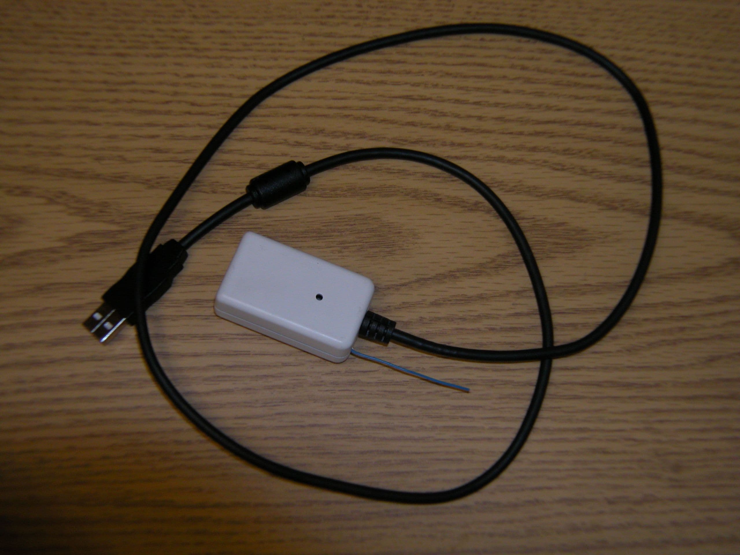
Click to zoom
Application Details
- Equipment Class
- DXT - Part 15 Low Power Transceiver, Rx Verified
- Date of Grant
- Sep 28, 2004
- Application Purpose
- Original Equipment
- Date of Application
- Sep 28, 2004
- Equipment Note
- FSK Transmitter
- Frequency Range
- 908.20000000 - 908.20000000
- Country
- United States
Documents & Files
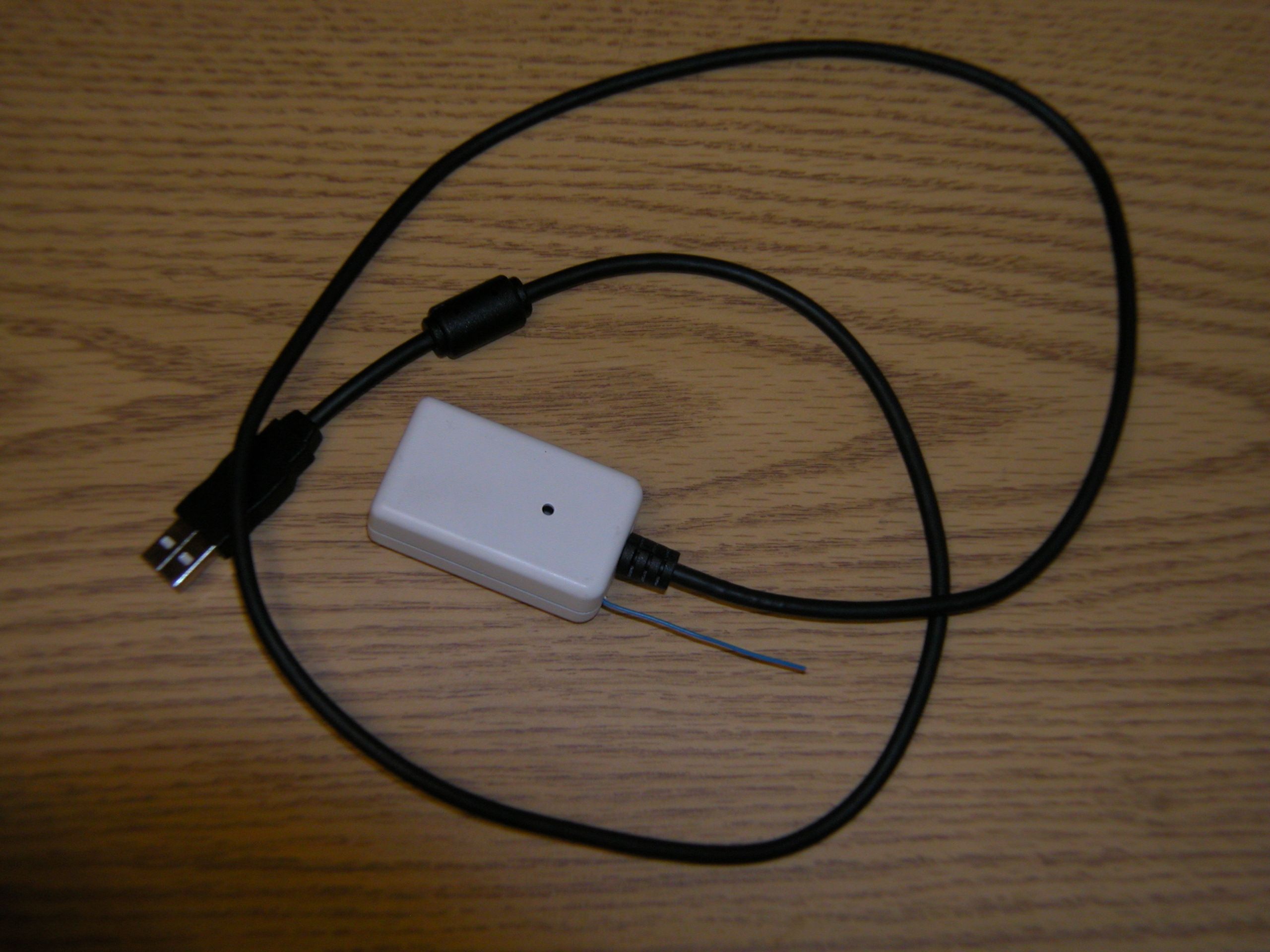


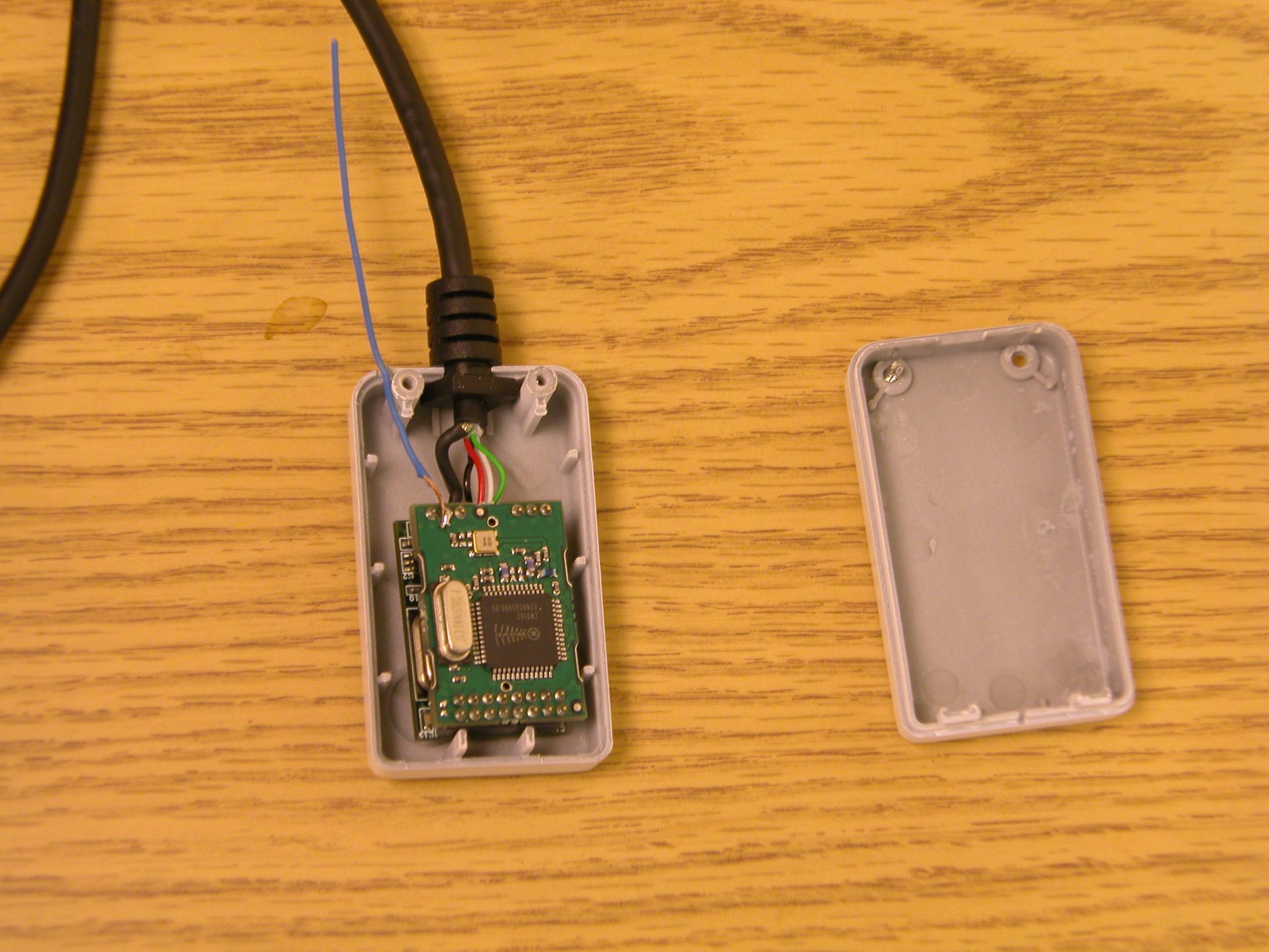
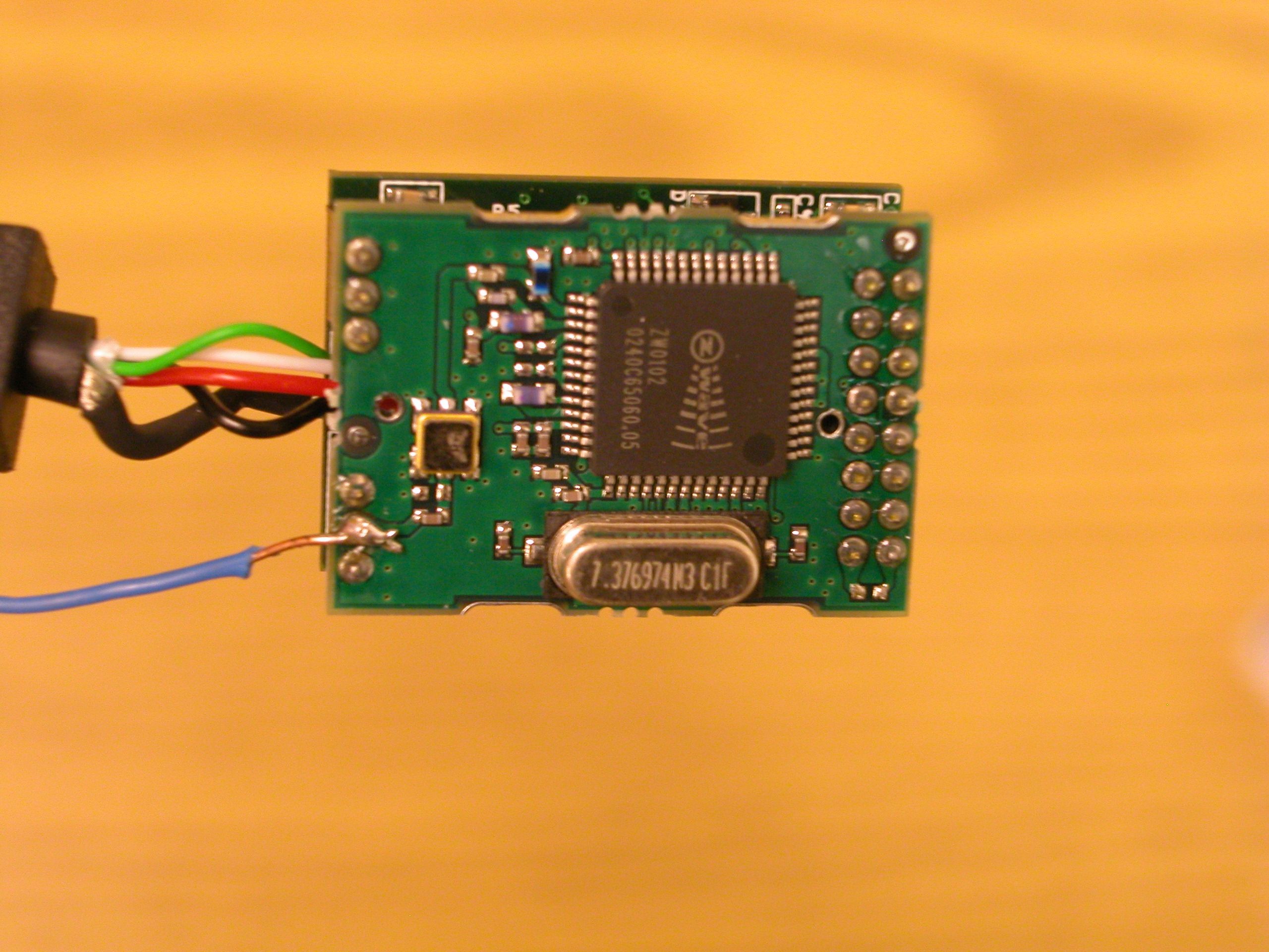
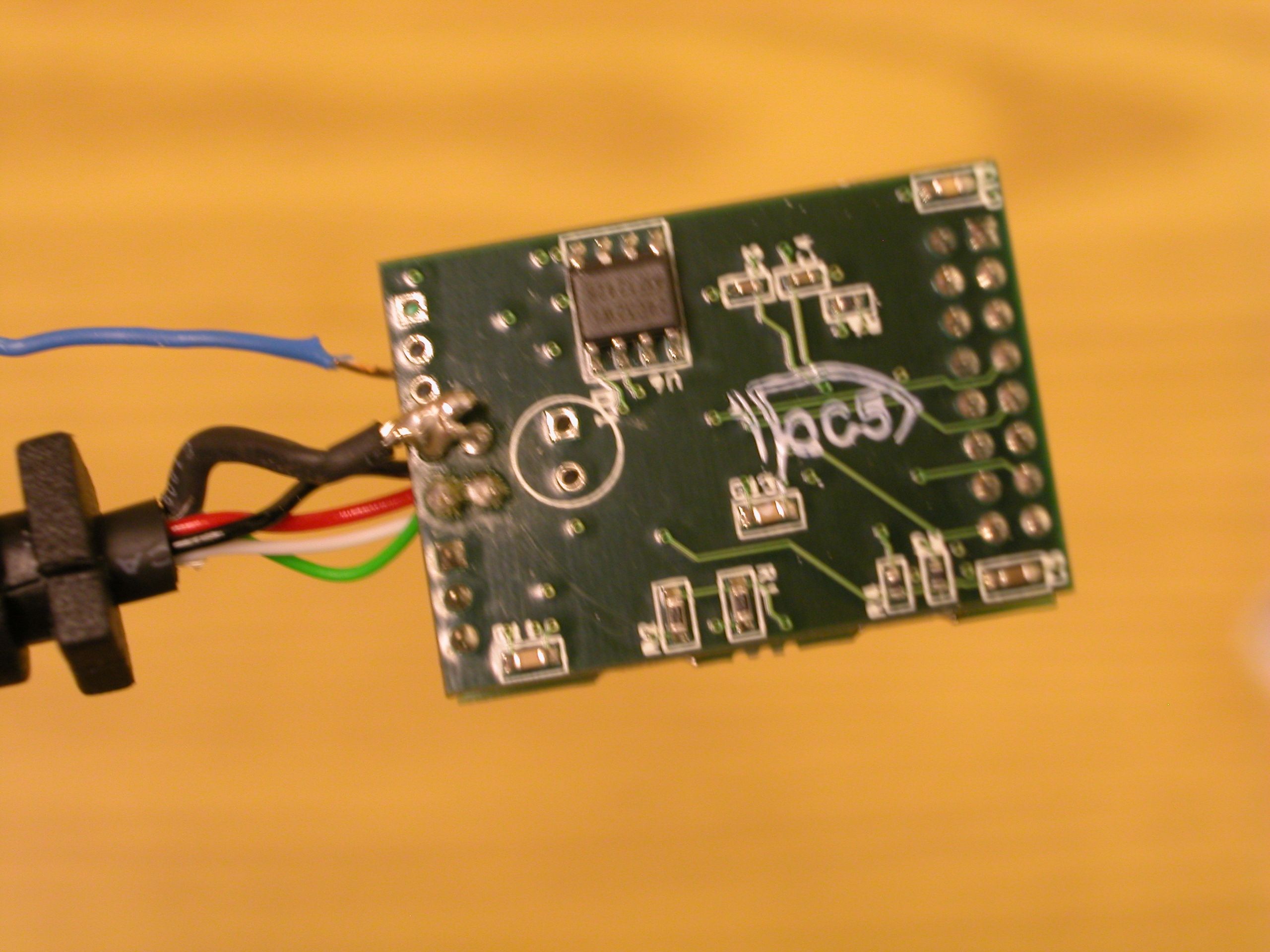
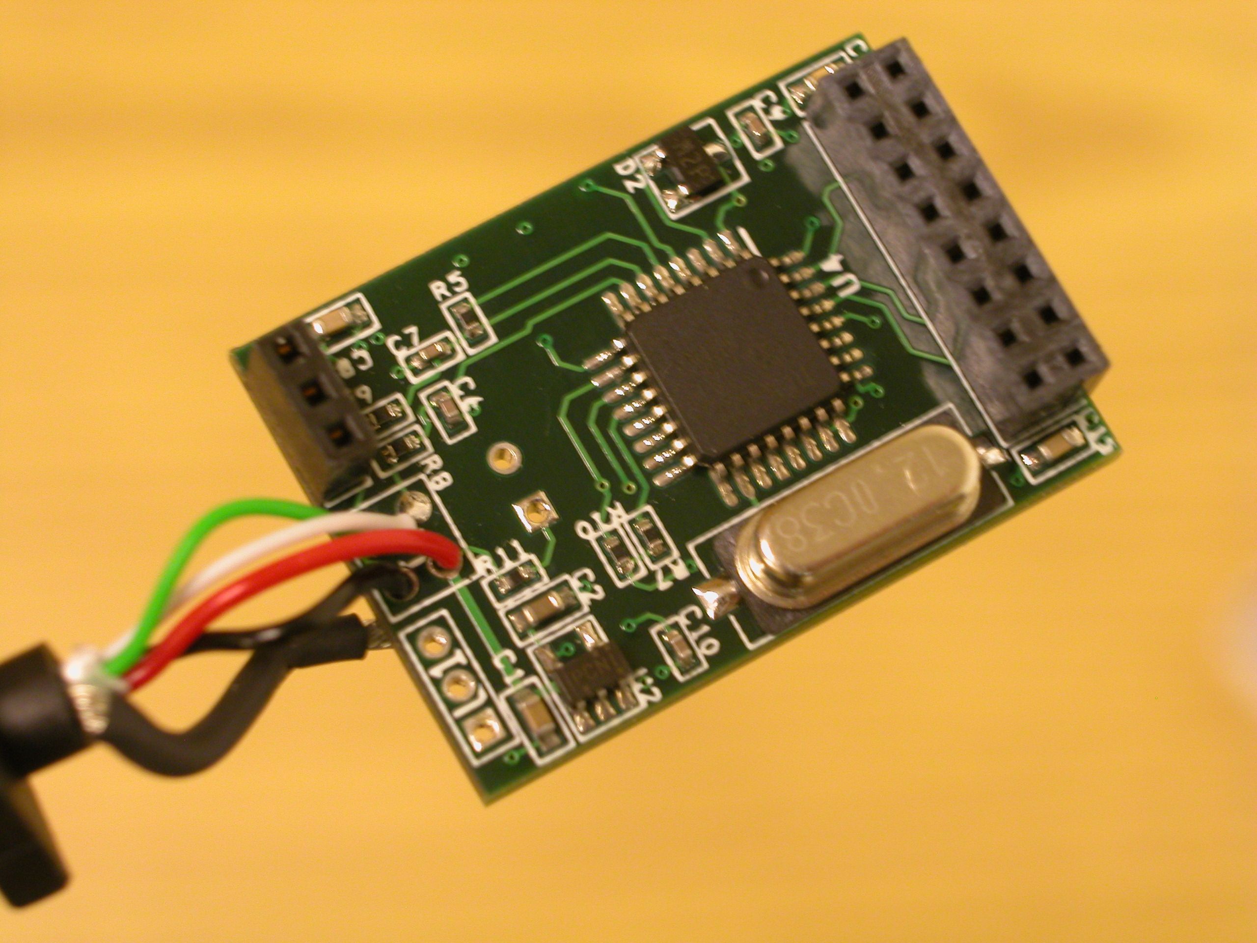
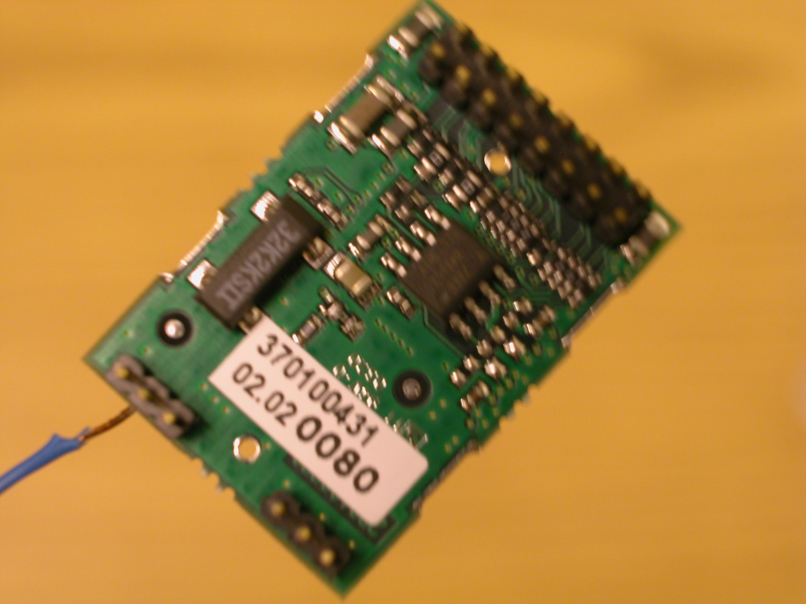
Document Text
Text extracted from the exhibit documents filed with the FCC. Open a document above to read the original.
Users Manual
Cielo Lighting Control Package Table of Contents FCC Compliance............................................................................................................. 3 Introduction..................................................................................................................... 4 Getting Started................................................................................................................4 Navigation buttons....................................................................................................... 4 Lights............................................................................................................................... 5 Adding a lamp module................................................................................................. 5 Controlling lights.......................................................................................................... 6 Removing a lamp module............................................................................................ 6 Scenes............................................................................................................................ 7 Activating a Scene....................................................................................................... 7 Creating a new Scene................................................................................................. 7 Schedule......................................................................................................................... 8 Viewing scheduled Scenes.......................................................................................... 8 Set a new Scene schedule.......................................................................................... 8 Delete a Scene schedule............................................................................................. 8 Status.............................................................................................................................. 8 FCC Compliance This equipment has been tested and found to comply with the limits for a Class B digital device, pursuant to Part 15 of the FCC Rules. These limits are designed to provide reasonable protection against harmful interference in a residential installation. This equipment generates, uses and can radiate radio frequency energy and, if not installed and used in accordance with the instructions, may cause harmful interference to radio communications. However, there is no guarantee that interference will not occur in a particular installation. If this equipment does cause harmful interference to radio or television reception, which can be determined by turning the equipment off and on, the user is encouraged to try to correct the interference by one or more of the following measures: ♦ ♦ ♦ ♦ Reorient or relocate the receiving antenna. Increase the separation between the equipment and receiver. Connect the equipment into an outlet on a circuit different from that to which the receiver is connected. Consult the dealer or an experienced radio/TV technician for help. Caution: Any changes or modifications of this product not expressly approved by CasaWorks may void your authority to use the product. Introduction The CasaWorks Cielo Lighting Control Package, along with a personal computer and standard lamps, makes it possible to retrofit a home for intelligent lighting control without having to run wires. The included software takes you step by step through the process of installing the Z-PC USB to Z-Wave Bridge and adding Z-Wave lamp modules. Even the first time user can have the first lamp module responding to computer commands in no time. In planning your lighting control system, be aware that Z-Wave devices have a distance limitation of 50 – 100 feet, depending on walls and other structures that may interfere with communications. But, since all Z-Wave devices on the system act as signal repeaters, the total distance from the Z-PC USB to Z-Wave Bridge to any Z-Wave controlled light is virtually unlimited, as long as the distance from one Z-Wave device to the next along the way is within this distance. Getting Started 1. DO NOT plug in the Z-PC USB to Z-Wave Light Bridge until the drivers have been installed. 2. Insert the Cielo Lighting Control Package CD into the computer’s CD-ROM drive. If the program does not auto-start: a. Click “Start” b. Click “Run”. c. Click “Browse” d. Click on the drive letter of your CD-ROM e. Double click setup.exe 3. Follow the on-screen instructions to install the drivers and program. 4. When prompted, plug the included Z-PC USB to Z-Wave Light Bridge into any available USB port on your computer. 5. Allow Windows to detect and install the new hardware. 6. Once the installation is complete, click the “Finished” button. 7. Double click the Cielo Lighting Control Package icon to start the program. Navigation buttons On the left side of the screen are buttons that will bring you quickly to the various parts of the program. The following sections will show you how to use each one. Lights This section is used to manually control lights, install new lights and give them names, and remove lights from the system. Adding a lamp module Before the program can control a light, it must be installed on the system. This procedure will guide you through the steps required. 1. Take any Z-Wave lamp module from the package and plug it into an electrical outlet close to the computer (within 5 feet). Plug a lamp into the lamp module and turn it on. The lamp may not actually light up until the Z-Wave lamp module is activated, either remotely by the program or by pressing the button located on the lamp module. 2. On the computer screen, click the “Lights” button. This screen allows you to control lights that have already been installed and will be explained in the next section. 3. At the bottom of the screen, click the “Add a New Light” button. 4. At the next s…
Text truncated - open the document above for the full version.
Block Diagram
RF Module Block Diagram RF Matching / Filtering 908.42MHz Antenna RF_IN RF_OUT RF Transceiver Crystal 7.376974MHz RF Transceiver Block Diagram CRYSTAL 7.376974MHz /N LNA MIXER IF STAGE (150kHz) DEMODULATOR PA VCO (908.27MHz) CONTROL including - MANCHESTER ENCODING / DECODING - PREAMPLE DETECTION - SERIALIZATION / DESERIALIZATION OSC CHARGE PUMP /RPD CPU Interface XO SC _ Q 1 XO SC _ Q 2 L1L2 RF_IN RF_OUT BIAS RB IAS VCO INDUCTOR CONNECTIONS BIAS RESISTOR CONNECTION RF (908.42MHz)
Cover Letter(s)
FW Non-Conformities FCC ID R94Ø 7 2 Ø Ø 4 (Ref # E04-000084-1).txt From: Todd Seeley [[email protected]] Sent: Wednesday, September 22, 2004 12:17 PM To: 'Randal Clark' Subject: FW: Non-Conformities FCC ID: R94Ø 7 2 Ø Ø 4 (Ref # E04-000084-1) Importance: High Randy: Please see the email string below. Thanks, Todd Seeley Principal Engineer Direct Phone: (303) 402-5272 Email: [email protected] CONFIDENTIALITY NOTICE: ATTENTION! This electronic mail and any attachments contain information which is the property of the sender and which may be confidential and legally privileged. The information in this transmission is intended ONLY for the use of the person or entity to whom the electronic mail was sent, as indicated within the body of the message, above. If you are not the intended recipient, any disclosure, copying, distribution, dissemination, or action taken in reliance on the contents of the information contained in this transmission is strictly prohibited. If you have received this Transmission in error, please call this office collect at 303-786-7999 to let us know and delete all copies of this message immediately. Thank you. -----Original Message----- From: Todd Seeley [mailto:[email protected]] Sent: Friday, September 17, 2004 1:32 PM To: '[email protected]' Cc: 'Todd Seeley' Subject: RE: Non-Conformities FCC ID: R94Ø 7 2 Ø Ø 4 (Ref # E04-000084-1) Importance: High Randy: Please see my comments below. I will be uploading the report. Thanks, Todd Seeley Principal Engineer Direct Phone: (303) 402-5272 Email: [email protected] CONFIDENTIALITY NOTICE: ATTENTION! This electronic mail and any attachments contain information which is the property of the sender and which may be confidential and legally privileged. The information in this transmission is intended ONLY for the use of the person or entity to whom the electronic mail was sent, as indicated within the body of the message, above. If you are not the intended recipient, any disclosure, copying, distribution, dissemination, or action taken in reliance on the contents of the information contained in this transmission is strictly prohibited. If you have received this Transmission in error, please call this office collect at 303-786-7999 to let us know and delete all copies of this message Page 1 FW Non-Conformities FCC ID R94Ø 7 2 Ø Ø 4 (Ref # E04-000084-1).txt immediately. Thank you. -----Original Message----- From: [email protected] [mailto:[email protected]] Sent: Wednesday, September 15, 2004 11:25 PM To: [email protected] Subject: Non-Conformities FCC ID: R94Ø 7 2 Ø Ø 4 (Ref # E04-000084-1) Non-Conformities FCC ID: R94Ø 7 2 Ø Ø 4 (Ref # E04-000084-1) The items listed below represent requests for information following review of this application. Further question may arise pending review of responses to these items. Item 1. Equipment class DTS is not applicable to this product. DTS is reserved for equipment under 15.247. It appears that equipment class DXT is more appropriate, please confirm. ********* I agree. I did not select the correct code. ******************** Item 2. Freuqency range indicated on form 731 indicates a multi channel equipment. If this device is a single channel device, please indicate center frequency of transmitter. ********** Randy... it is a single channel device. I made a mistake in filling out the 731 form. The frequency should not have a range but a single freq. Sorry for the inconvenience ************ Item 3. There is no supporting test equipment for testing performed below 30MHz. Please provide test equipment used for this frequency range. ********The report has been updated to reflect the Magnetic Loop Antenna used to test below 30MHz********** Item 4. Some measurements reported indicate QP readings. Test equipment list in test report does not list QPA. Please clarify. ********I have added and updated the equipment list to reflect the 8594EM that was utilized for the 30-1000MHz testing for the QP measurements***** Item 5. Please include all frequencies used for each block in the block diagram including the tuning range(s) and intermediate frequency(ies). **** I am requesting that from the client. I will upload it ASAP****** Item 6. The internal photos provided are do not clearly show adequate detail of the circuitry of the product. Occasionally, this is due to the photo's inclusion into a document and resizing. Please provide internal photos showing clear detail of the PCB. **** that is the reason why they are not clear enough. I will upload them separately.******* Item 7. Please include a description of peripherals used during testing. ***** The EUT was connected to a computers USB port and the test setup during part 15.209 represented that of a class B setup per ANSI 63.4. After that testing was completed, the computer was removed from the field to complete the intentional emissions testing of the product. Item 8. EUT support structure used for testing appears to be a wooden block. Such material has been known to be a good RF absorber; please confirm Page 2 FW Non-Conformities FCC ID R94Ø 7 2 Ø Ø 4 (Ref # E04-000084-1).txt whether emissions increase using non-conductive foam support structure. Provide updated test data where necessary. ****** You are very correct on that fact. However, we always take measurements with and without any support utilized during testing for the fact that wee have observed RF absorption as well in colored plastics and foam due to the metal in the coloring. During the preliminary support testing, it is verified that there is no effect on the intentional emissions testing due to the support. We did not use a foam support though we did make sure that the wooden block would not effecting the testing. ********** All Best, Randal Clark CKC Certification Services. The items indicated above must be submitted before processing can continue on the referenced application. Failure to provide the requested information within 60 days may result in application dismissal purs…
Text truncated - open the document above for the full version.
ID Label/Location Info
CasaWorks Cielo Z-PC USB Transceiver Model: Z-PC S/N: 04070000001 This device complies with part 15 of the FCC Rules. Operation is subject to the following two conditions: (1) This device may not cause harmful interference, and (2) this device must accept any interference received, including interference that may cause undesired operation. Patent Pending FCC ID: R94072004
Operational Description
Product Description Cielo Z-PC, will enable home owners to access common options and controls using the Z-Wave wireless protocol. Cielo Z-PC is a USB to Z-Wave enabled transceiver that is used for communicating with other Z-Wave enabled devices such as; • light switch dimmers • thermostats • window shades and drapes • operable windows • door strikes • garage door openers An example of the products including the Cielo Z-PC is a Cielo Z-Wave Lighting Control Package which includes the Z-PC device and PC based software that provides status display and graphical icons that can be used to control Z-Wave enabled light switches and dimmers via a PDA or PC. A set of out-of-the-box home lighting behaviors and ability to create custom lighting scenes is supported. 802.11 wireless network control can be added to the PC that the Z-PC is connected to via USB so that a WiFi enabled PDA device can act as a universal remote that can be carried throughout the home. Theory of Operation The Cielo Z-PC adds a USB bridge communicating with the ZM1206 (Z-Wave) application module through the standard application connector provided on the Z-Wave Application Module blueprint. For specific information on circuit functionality and antenna implementation of the Z-Wave ZM1206 Application module please refer to the file 903501802.pdf. The implementation of the USB bridge communication uses a TI USB3410 micro- controller. For detailed information on this device refer to the TI data sheet.
Test Report
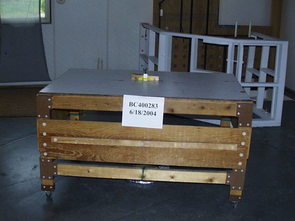
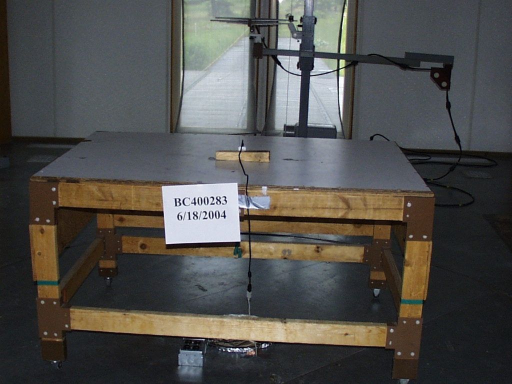
EMC EMISSIONS - TEST REPORT (Full) Test Report No. BC400283 -1 Issue Date: Fri 2/Jul/2004 Model / Serial No. Z-PC / SN: 001 Product Type USB Wireless Transceiver Client INTERTest Manufacturer Casaworks License holder Metrics Technology, Inc. DBA CasaWorks 3830 Commons Ave. NE Address Albuquerque, NM 87109 Test Criteria Applied FCC CFR47 Part 15 Test Result PASS Test Project Number References BC300322 Total Pages Including Appendices: 28 Title 47 CFR 15: RADIO FREQUENCY DEVICES Reviewed By : Approved By : INTERNATIONAL APPROVALS LABORATORIES (IAL) reports apply only to the specific samples tested under stated test conditions. It is the manufacturer's responsibility to assure that additional production units of this model are manufactured with identical electrical and mechanical components. IAL have no liability for any deductions, inferences or generalizations drawn by the client or others from IAL issued reports. This report is the confidential property of the client. As a mutual protection to our clients, the public and ourselves, extracts from the test report shall not be reproduced except in full without our written approval of IAL. This report shall not be used by the client to claim product endorsement by NVLAP (No. 200624- 0) or any agency of the US government. International Approval Laboratories and its professional staff hold government and professional organization certifications and are members of IEEE, NVLAP, and VCCI. Project File: BC300332 Page 2 of 28 International Approvals Laboratories, LLC 5541 Central Avenue, Suite 110 Boulder, Colorado 80301 Voice: 303 786 7999 Fax: 303 449 6160 Rev.No 1 D I R E C T O R Y Documentation Page(s) Test report 1 - 28 Directory 2 Test Regulations 3 - 4 General Remarks 5 - 6 Test-setup Photographs 7 - 9 Appendix A Test Data Sheets and Test Equipment Used 10 - 22 Appendix B Test Plan/Constructional Data Form 23 Appendix C Measurement Protocol/Test Procedures 24 - 28 STATEMENT OF MEASUREMENT UNCERTAINTY The data and results referenced in this document are true and accurate. The measurement uncertainty for Conducted Emissions in the frequency range of 150kHz – 30MHz is calculated to be ±2.30dB and for Radiated Emissions is calculated to be ±3.60dB in the frequency range of 30MHz – 200MHz and ±3.38dB in the frequency range of 200MHz – 1000MHz. EUT Received Date: 18-Jun-2004 Testing Start Date: 18-Jun-2004 Testing End Date: 18-Jun-2004 Project File: BC300332 Page 3 of 28 International Approvals Laboratories, LLC 5541 Central Avenue, Suite 110 Boulder, Colorado 80301 Voice: 303 786 7999 Fax: 303 449 6160 Rev.No 1 The tests were performed according to following regulations: 1. FCC CFR47 Part 15.207 2. FCC CFR47 Part 15.209 3. FCC CFR47 Part 15.249 Emission Test Results: Conducted Emissions, Powerline - 15.207 - (Not Applicable) Test Result Minimum limit margin dB at MHz Maximum limit exceeding dB at MHz Remarks: Conducted Emissions, Data I/O (Ethernet, RJ11, etc.) - (Not Applicable) Test Result Minimum limit margin dB at MHz Maximum limit exceeding dB at MHz Remarks: Radiated Emissions (Electric Field) - 15.209 - PASS Test Result Minimum limit margin -13.0 dB at 10000.00 MHz Maximum limit exceeding dB at MHz Remarks: Fundamental Field Strength Measurement Radiated Emissions (Electric Field) - 15.249(a) - PASS Test Result Minimum limit margin -0.30 dB at 908.20 MHz Maximum limit exceeding dB at MHz Remarks: Radiated Emissions Harmonic Emissions Radiated Emissions (Electric Field) - 15.249(a) - PASS Test Result Minimum limit margin -4.30 dB at 2725.08 MHz Maximum limit exceeding dB at MHz Remarks: Project File: BC300332 Page 4 of 28 International Approvals Laboratories, LLC 5541 Central Avenue, Suite 110 Boulder, Colorado 80301 Voice: 303 786 7999 Fax: 303 449 6160 Rev.No 1 Average Measurements for Emissions >1GHz Radiated Emissions (Electric Field) - 15.249(d) – PASS Test Result Minimum limit margin dB at MHz Maximum limit exceeding dB at MHz Remarks: No other emissions observed other than the fundamental and harmonics Project File: BC300332 Page 5 of 28 International Approvals Laboratories, LLC 5541 Central Avenue, Suite 110 Boulder, Colorado 80301 Voice: 303 786 7999 Fax: 303 449 6160 Rev.No 1 GENERAL REMARKS: The following remarks are to be considered as “where applicable“ and are taken into account while completing any FCC/IC/ETSI radio tests at International Approvals Laboratories, LLC. Testing was performed in 3 different orthogonal axis to determine the worst case emissions from the device. The worst case emissions measurements are shown in this report. FCC CFR47 Part 15.31: Measurement Standards: In any case where the device is powered off a battery, a fresh battery was used during test. In cases where the device is powered off an AC supply, voltage was varied per Part 15.31 to find worst case emissions. FCC CFR47 Part 15.35: Measurement Detector Functions and Bandwidths: FCC Part 15.35 was utilized when performing the measurements within this report. In any case where the device is powered off a battery, a fresh battery was used during test. In cases where the device is powered off an AC supply, voltage was varied per Part 15.31 to find worst case emissions. The actual test distance for the FCC Part 15.209 testing was conducted at 10m for the fact that the device was being tested to EN55022 Class B from 30 MHz to 1000 MHz (meets/exceeds the FCC Part 15.209 & 109B limits) The data is automatically extrapolated back to the FCC 3m limits and measurements are corrected to better show the compliance to FCC requirements and reduce confusion. A correction factor of 10.54dB is used in cases of 30MHz and up for a difference between 10m and 3m measurement distances. All measurements that are lesser than 30MHz where applicable are accompanied with the fall of measurements and calculations to support the interpolation. The Duty Cycle Correction Calculations are detailed in the operational description for this device. Modifications required to pass: NONE…
Text truncated - open the document above for the full version.
Contact Information
Applicant
Michael D Arendall(President/CEO)
Technical Contact
Metrics Technology, Inc. DBA CasaWorksMichael Arendall
[email protected]505-761-9642
3830 Commons Ave NE · Albuquerque, New Mexico · United States
Non-Technical Contact
Metrics Technology, Inc. DBA CasaWorksMichael Arendall
[email protected]505-761-9642
Test Firm
International Approval Laboratories, LLCTodd Seeley
Technical Specifications
| # | Rule Parts | Frequency Range | Power Output |
|---|---|---|---|
| 1 | 15C | 908.2 MHz - 908.2 MHz | - |