RBODS80TBELTPACK TRANSMITTER
SABINE, INC.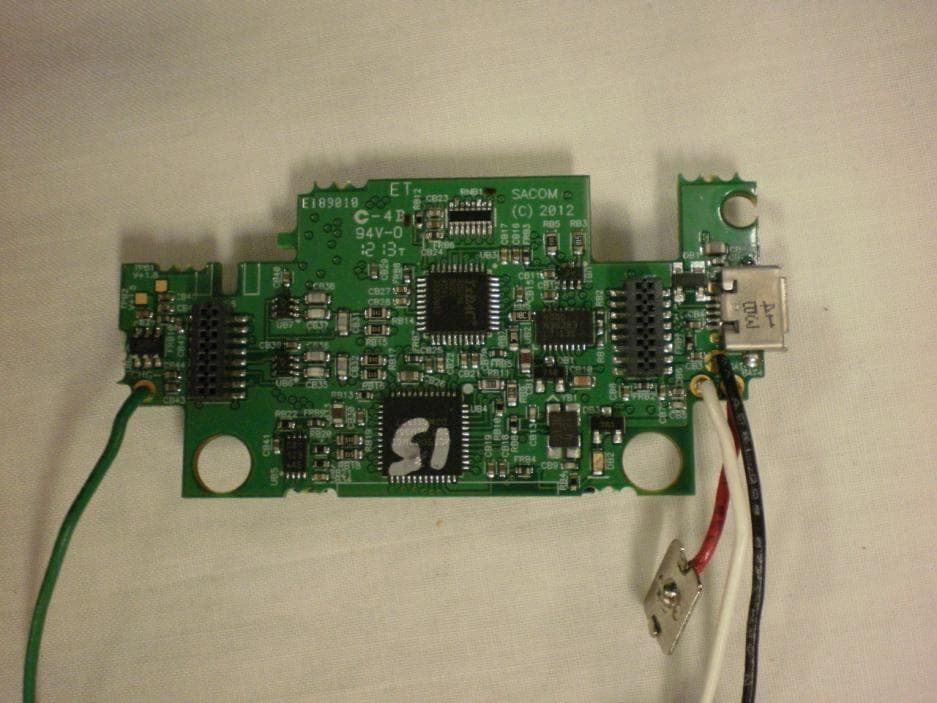
Click to zoom
Application Details
- Equipment Class
- DTS - Digital Transmission System
- Date of Grant
- Jun 11, 2013
- Application Purpose
- Original Equipment
- Date of Application
- Jun 11, 2013
- Equipment Note
- BELTPACK TRANSMITTER
- Frequency Range
- 902.80000000 - 927.20000000
- Company
- SABINE, INC.
- Country
- United States
Documents & Files
Document Text
Text extracted from the exhibit documents filed with the FCC. Open a document above to read the original.
Users Manual
Digital Wireless Microphone Systems Quick Start Guide Setting Up Pre-Engineered SACOM Systems for Optimal Performance Open the Cartons: Confirm everything on the packing slip is enclosed. Set up the Docking Station:1. SACOM transmitters are shipped with rechargeable batteries. Plug in the charging dock, put the batteries in the transmitters, then place the transmitters in the dock while you set up the rest of the system. Mount the Receivers in the Rack2. and connect them to power. Confirm the displays light up. Pre-engineered Antenna Design: 3. If you provided SACOM with a floor plan, you will find a marked up version in the box (or, in your Email in-box) showing the antenna design along with the antennas and pre-made cables. Place the antennas according to the drawings. Your Own Design: A. If you did not request an antenna design, place the antennas according to the enclosed Antenna Applications Guide or download it from www.SacomUSA.com > Downloads. Improper antenna placement is the main cause of poor RF performance. Dipole Antennas: B. Dipole antennas mounted to the rack equipment can easily be locked away in a closet/rack cabinet. This results in poor RF performance because there is no line of sight between the transmitter and receiver antenna. Therefore, remote antennas are preferred. See the Antenna Application Guide for details. Connect the Antennas:4. The receiver that connects to the antennas should be set as the Antenna Master receiver. Master is the factory default. If your system daisy-chains antennas together, the downstream receivers should be set as Slaves. Terminators are used on the last system in the daisy-chain. Use SACOM Remote’s Antenna Setup Wizard, which opens automatically the first time you connect. You can also find the wizard under the SETTINGS tab of the main page. If connecting Sacom active remote antennas, make sure the red LED lights up. If not, check the receiver’s antenna phantom power setting using the Sacom Remote Control Software. Connect the analog outputs to the mixer:5. The system is shipped with either XLR or Euro block connectors. The default output level is set to +4 dBu. Note that factory default for the front panel headphone jack is set for mixed line-level out. Use SACOM Remote>Settings>Headphone, to reset for headphones. CAUTION! Turn off phantom power from the mixer. Phantom power distorts the audio quality of your microphones. System Test:6. In most cases, the system is now ready to use. Confirm all channels pass audio perfectly. Master Slave Terminators SABINE INC. l 13301 NW US Highway 441 l Alachua, Florida 32615-8544 USA l Phone: +USA (386) 418-2000 l Fax: +USA (386) 418-2001 l www.SacomUSA.com Modifications (FCC 15.21) Changes or modifications to this equipment not expressly approved by Sabine, INC may void the user’s authority to operate this equipment. This device complies with Industry Canada licence-exempt RSS standard(s). Operation is subject to the following two conditions: (1) this device may not cause interference, and (2) this device must accept any interference, including interference that may cause undesired operation of the device. On site, remote commissioning of SACOM Systems is available at no additional cost. For support please call USA (+1) (386) 418-2000 between the hours of 9 - 5 EST., Monday thru Friday. Note: SACOM offers free pre-engineering so that the systems arrive at your job site ready to plug and play. Applies to DS80-T: Under Industry Canada regulations, this radio transmitter may only operate using an antenna of a type and maximum (or lesser) gain approved for the transmitter by Industry Canada. To reduce potential radio interference to other users, the antenna type and its gain should be so chosen that the equivalent isotropically radiated power (e.i.r.p.) is not more than that necessary for successful communication. This radio transmitter (DS80-T) has been approved by Industry Canada to operate with the antenna types listed below with the maximum permissible gain and required antenna impedance for each antenna type indicated. Antenna types not included in this list, having a gain greater than the maximum gain indicated for that type, are strictly prohibited for use with this device. Monopole antenna, 0dbi gain, 50 ohm impedance. Le présent émetteur radio (DS80-T) a été approuvé par Industrie Canada pour fonctionner avec les types d’antenne énumérés ci-dessous et ayant un gain admissible maximal et l’impédance requise pour chaque type d’antenne. Les types d’antenne non inclus dans cette liste, ou dont le gain est supérieur au gain maximal indiqué, sont strictement interdits pour l’exploitation de l’émetteur. For Full Control Select the new parameter values and click OK to save changes to the receiver. Editing Transmitter Parameters: The easiest and most intuitive way to set the parameters of SACOM ™ transmitters and receivers is with SACOM ™ Remote software. Load SACOM ™ Remote (from disk or download from www.SacomUSA.com) onto a computer running Windows XP or Windows 7 (32 or 64-bit) and connect to the receiver via USB or RS232. Then open SACOM ™ Remote and select ONLINE. Open The Channel Edit Window: 1) The [Click to Edit] function opens the edit window of the channel you wish to edit. 2) Select the functions you want to edit and enter the parameter. (The various functions are described below.) Click [OK] to save the changes and close the Channel Edit window. 3) You will notice that the [Needs to Sync] alert is lit. This indicates that one or more parameters are in queue in the receiver ready to be downloaded and implemented with the next transmitter Sync of the channel. 1) 2) Digital Wireless Microphone Systems Using the SACOM remote software: Click to Edit the channel’s parameters 3) The “Need To Sync” alert is lit. Sync the transmitter to apply the selected parameters. SACOM Remote provides the following functions: File:1. Save a PDF image of the screen. Settings:2. Phantom Power:A. Turn antenna phan…
Text truncated - open the document above for the full version.
Users Manual
BACK PANEL (XLR Connector): Antenna A Input:1. TNC connector for dipole antennas (included), front-to-back antenna cables (included), or antenna cable to active extension antenna. Antenna A Output:2. Daisy-chain to the input of another receiver-frame to form an antenna network. Power Cord Input:3. (Cord with local plug configuration Included). 100-240 VAC, 50/60Hz, 15 W, 250V 320mA slow-blow fuse (spare included) Ethernet:4. Connect to a computer or network. Multiple receiver-frames can be daisy-chained together to form a network. (Under construction) AES/EBU-3 Digital-Audio Output:5. Uses the standard Yamaha wiring convention(1). (NOTE: This feature is optional. The connector jack is included on all receivers, but the feature must be specified at the time of purchase. It cannot be added at a later date.) BNC connectors:6. for word clock digital-audio synchronizing. GPIO/RS232:7. This connector combines a General Purpose Input / Output (GPIO) and a RS232 on one DB25 connector. The RS232 can be disabled to add up to 24 GPIO pins. RS232: The pinout for the RS232 is the standard pinout. Pin 2 on the receiver is transmit, pin 3 is receive, and pin 7 is ground. Most computers now use a DB9 connector for RS232. The standard off-the-shelf DB9 to DB25 cable will work. This cable swaps pins 2 and 3 internally. If you computer has a DB25 connector for RS232, use a straight DB25 to DB25 cable. Do not use a null modem cable. GPIO: GPIO acts like a contact closure. Use SACOM ™ Remote to assign an event that toggles the GPIO pin. The factory default toggles pins X through X to correspond to muting a receiver module. SACOM ™ Remote has a feature that lets you assign how the system responds to a transmitter mute (see SACOM Remote) A. Mute the channel’s receiver audio. (Factory default) B. Toggle the GPIO but do not mute the receiver audio. Use this with automated mixers or echo cancelling DSPs. C. Mute the channels receiver audio and toggle the GIPO pin. Audio Output Jacks:8. Configured for four or eight-module receiver frames and for XLR or Euro-block terminal connectors. Antenna B Input:9. TNC connector for dipole antennas (included), front-to-back antenna cables (included), or antenna cable to active extension antenna (see section on antennas, antenna placement and antenna cables). Antenna B Output:10. Daisy-chain to the input of another receiver-frame to form an antenna network. 8 Digital Wireless Microphone Systems Receiver: SABINE INC. l 13301 NW US Highway 441 l Alachua, Florida 32615-8544 USA l Phone: +USA (386) 418-2000 l Fax: +USA (386) 418-2001 l www.SacomUSA.com MIC OUTPUTS AES3 50-60 Hz 100-240 VAC ANTENNA A ETHERNET WORD CLOCK ANTENNA B RS 232-GPIO 4 G - + 3 G - + 2 G - + 1 G - + 8 G- + 7 G - + 6 G - + 5 G - + Mfgr: Sabine, Inc., Alachua, FL. DS8800 Made In USA TM OUT IN IN OUT OUT IN BACK PANEL (Euro-Block Connector): MIC OUTPUTS IN AES3 IN 50-60 Hz 100-240 VAC ANTENNA A 1 2 3 4 ETHERNET WORD CLOCK ANTENNA BRS 232-GPIO 5 6 7 8 Mfgr: Sabine, Inc., Alachua, FL. DS8800 Made In USA TM IN OUT OUT OUT 2 3 4 7 1 5 6 9 8 2 3 4 7 1 5 6 9 Digital Wireless Microphone Systems Transmitters: 1. Heads: Five (5) microphone elements are available, both condenser and dynamic, depending on the application of the microphone user (including Audix OM3 and OM5 dynamic heads). In general, condenser heads are more “transparent” and do not require the microphone to be held as close to the mouth. On the other hand, dynamic heads are often preferred for live performance because they tend to accent the bass tones and they do not distort with very loud singing. 2. Display: OLED display is used to program and display the current status of the transmitter functions. 3. Switch: User programmable to toggle on/off, on/mute/ or on/on. 4. Battery and Control Cover: Unscrew counter-clockwise and gently slide open. 5. Antenna Cover: Do not hold the antenna cover. Your hand will shield the RF signal and cause poor audio performance. 6. IR Sensor Port: The IR sensor is used to transfer channel settings and a random encryption key from the receiver to the transmitter. 7. Select button: Press this button to select a function. The first press activates the first edit able function in the tree. Press again to move to the next edit able function. 8. Parameter Up: Press this button to increase the value of the selected function. 9. Parameter Down: Press this button to decrease the value for the selected function. 10. USB Port: Plug a micro USB cable into the USB port to charge the batteries or upgrade the firmware. 11. Batteries: (not shown) AA NiMH, 2200 to 2500-mAHr recommended. 12. Battery Door: Open position. 7 10 6 9 12 8 11 2 3 1 4 5 7 6 8 9 5 6 7 s 8 2 3 1 4 9 10 12 11 13 10 13 1. Antenna: Length and style varies with the transmitters model number. Antennas are field replaceable to improve reliability and redundancy. 2. Programmable Switch: Toggle on/off, on/mute/ or on/on. 3. Microphone Connector: TA4 mini XLR style: SACOM ™ offers a full range of lavaliere and headset microphones for optimal performance of your SACOM ™ transmitter. Works with both snap in and screw-in microphones. 4. Display: OLED display is used to program and display the current status of the transmitter functions. 5. IR Sensor Port: The IR sensor is used to transfer channel settings and a random encryption key from the receiver to the transmitter. 6. Select: Press this button to select a function. The first press activates the first edit able function in the tree. Press again to move to the next edit able function. 7. Parameter Down: Press this button to decrease the value for the selected function. 8. Parameter Up: Press this button to increase the value of the selected function. 9. Batteries: AA NiMH, 2200 to 2500-mAHr recommended. 10. Battery Door Locks: To open, press both at the same time and lift the door open. To close, snap the door closed. 11. USB Port: Plug a micro USB cable into the USB port to charge the batteries or upgrade the firmware. 12. B…
Text truncated - open the document above for the full version.
ID Label/Location Info
FCC label location for Sacom DS80T bodypack transmitter: Label: In transmitter (following page):
Internal Photos
APPLICANT: SABINE INC. FCC ID: RBODS80T INTERNAL PHOTOS
Operational Description
The Sabine Sacom DS8000 wireless microphone system consists of a receiver (DS88) and one or more transmitters (DS80T or DS80P or DS80H or DS80B). The DS80T is a “beltpack” transmitter that is designed to be worn by the user. The DS80P is a “podium” transmitter that is designed to be used with a gooseneck microphone. The DS80B is a tabletop boundary microphone transmitter that is designed to be place on a conference room table. The DS80H is a handheld microphone transmitter that is designed to be held by a performer. The DS80T and DS80P do not contain a built-in microphone, but instead have connectors designed to accept various lavalier and gooseneck microphones. The DS80B and have a microphone capsule built- in. These 4 transmitters have identical RF circuits. The transmitters contain a microcontroller that drives the OLED display and handles the user interface functions, and an FPGA that handles the modulation and formatting of the digital audio data from the A/D converter. The data is sent using AES 256 bit encryption. The transmitters use pi/4 DQPSK modulation to encode the audio onto the 902-928 MHz carrier. The modulation bandwidth is 600 kHz. The RF power level is user selectable between 1mW, 10mW. The DS80H and DS80P use internal helical antennas. The DS80B uses an internal monopole antenna. The DS80T uses an external monopole antenna. The transmitters transmit on any one of 16 preset channels, selected by the user. These are 1.6 MHz apart and cover the range from 902.8 MHz to 927.2 MHz. The transmitters are powered by 2 NiMH AA batteries and have a typical run time of approximately 6 hours on a full charge.
Test Report
FCC PART 15.247 AND IC RSS-210 TEST REPORT DIGITAL SPREAD SPECTRUM Applicant SABINE, INC. Address 13301 US HIGHWAY 441 ALACHUA FL 32615 USA FCC ID RBODS80T IC 8240A-DS80T Model Number DS80T Product Description WIRELESS MICROPHONE TRANSMITTER Date Sample Received 06/04/2013 Date Tested 06/05/2013 Tested By John A. Day Approved By Mario R. de Aranzeta Report Number 2464YUT12TestReport.doc Test Results PASS FAIL THE ATTACHED REPORT SHALL NOT BE REPRODUCED EXCEPT IN FULL WITHOUT THE WRITTEN APPROVAL OF TIMCO ENGINEERING, INC. 849 NW State Road 45 Newberry, FL 32669 USA Ph: 888.472.2424 or 352.472.5500 Fax: 352.472.2030 Email: [email protected] Website: www.timcoengr.com Testing Certificate # 0955-01 APPLICANT: SABINE, INC. FCC ID: RBODS80T IC: 8240A-DS80T REPORT: V:\S\SABINE_RBO\2464YUT12\Extra2464YUT12\2464YUT12TestReport.docx Page 2 of 17 Mdea 3.14.2008 TABLE OF CONTENT GENERAL REMARKS ........................................................................................................................... 3 GENERAL INFORMATION .................................................................................................................... 4 EMC EQUIPMENT LIST ....................................................................................................................... 5 TEST PROCEDURES ........................................................................................................................... 6 RADIATION INTERFERENCE ............................................................................................................... 7 POWER LINE CONDUCTED INTERFERENCE ..................................................................................... 10 OCCUPIED BANDWIDTH ................................................................................................................... 11 POWER OUTPUT ............................................................................................................................... 13 SPURIOUS EMISSIONS AT ANTENNA TERMINALS ............................................................................. 14 POWER SPECTRAL DENSITY ............................................................................................................. 17 APPLICANT: SABINE, INC. FCC ID: RBODS80T IC: 8240A-DS80T REPORT: V:\S\SABINE_RBO\2464YUT12\Extra2464YUT12\2464YUT12TestReport.docx Page 3 of 17 Mdea 3.14.2008 GENERAL REMARKS The attached report shall not be reproduced except in full without the written permission of Timco Engineering Inc. The test results relate only to the items tested. Summary The device under test does: fulfill the general approval requirements as identified in this test report not fulfill the general approval requirements as identified in this test report Attestations This equipment has been tested in accordance with the standards identified in this test report. To the best of my knowledge and belief, these tests were performed using the measurement procedures described in this report. All instrumentation and accessories used to test products for compliance to the indicated standards are calibrated regularly in accordance with ISO 17025: 2005 requirements. Testing Certificate # 0955-01 I attest that the necessary measurements were made, under my supervision, at: Timco Engineering Inc. 849 NW State Road 45 Newberry, Fl 32669 Authorized Signatory Name: John A. Day Engineering Project Manager Date: June 11, 2013 APPLICANT: SABINE, INC. FCC ID: RBODS80T IC: 8240A-DS80T REPORT: V:\S\SABINE_RBO\2464YUT12\Extra2464YUT12\2464YUT12TestReport.docx Page 4 of 17 Mdea 3.14.2008 GENERAL INFORMATION DUT Specification Applicable Standard Part 15.247 DUT Description WIRELESS MICROPHONE TRANSMITTER FCC ID RBODS80T IC 8240T-DS80T Operating Frequency TX: 902.8125 to 927.1875 MHz Number of channels 16 DUT Power Source 110–120Vac/50– 60Hz DC Power Battery Operated Exclusively Test Item Prototype Pre-Production Production Type of Equipment Fixed Mobile Portable Antenna Connector none Antenna Detachable monopole Test Facility Timco Engineering Inc. located at 849 NW State Road 45 Newberry, FL 32669 USA. Test Conditions Temperature: 26ºC Relative humidity: 50% Test Exercise The DUT was placed in continuous transmit mode of operation. Test Supporting Equipment Supporting Device Manufacturer Model / FCC ID Serial Number N/A APPLICANT: SABINE, INC. FCC ID: RBODS80T IC: 8240A-DS80T REPORT: V:\S\SABINE_RBO\2464YUT12\Extra2464YUT12\2464YUT12TestReport.docx Page 5 of 17 Mdea 3.14.2008 EMC EQUIPMENT LIST Device Manufacturer Model Serial Number Cal/Char Date Due Date 3-Meter Semi- Anechoic Chamber Panashield N/A N/A Listed 12/31/11 12/31/13 AC Voltmeter HP 400FL 2213A14499 CAL 6/12/11 6/12/13 Antenna: Active Loop ETS-Lindgren 6502 00062529 CAL 9/23/10 9/23/13 Frequency Counter HP 5385A 2730A03025 CAL 8/17/11 8/17/13 Hygro- Thermometer Extech 445703 0602 CAL 6/15/11 6/15/13 Modulation Analyzer HP 8901A 3435A06868 CAL 7/18/11 7/18/13 Digital Multimeter Fluke FLUKE-77 35053830 CAL 9/9/11 9/9/13 Analyzer Tan Tower Preamplifier HP 8449B-H02 3008A00372 CAL 10/28/11 10/28/13 Analyzer Tan Tower Quasi- Peak Adapter HP 85650A 3303A01690 CAL 10/28/11 10/28/13 Analyzer Tan Tower RF Preselector HP 85685A 3221A01400 CAL 10/28/11 10/28/13 Analyzer Tan Tower Spectrum Analyzer HP 8566B Opt 462 3138A07786 3144A20661 CAL 10/28/11 10/28/13 Temperature Chamber Tenney Engineering TTRC 11717-7 CHAR 7/03/12 7/03/14 Antenna ETS 3117 41534 10/5/12 10/5/14 Antenna Electro metrics LPA-25 1122 5/09/2013 5/09/2015 Antenna Electro metrics BIA-25 1171 6/13/12 6/13/14 APPLICANT: SABINE, INC. FCC ID: RBODS80T IC: 8240A-DS80T REPORT: V:\S\SABINE_RBO\2464YUT12\Extra2464YUT12\2464YUT12TestReport.docx Page 6 of 17 Mdea 3.14.2008 TEST PROCEDURES Radiation Interference: ANSI C63.4-2003 using a spectrum analyzer, a preselector, a quasi-peak adapter, and an appropriate antenna. The analyzer was calibrated in dB above a microvolt at the output of the antenna. The resolution bandwidth was 10…
Text truncated - open the document above for the full version.
Contact Information
Applicant
BYRA FERKOVICH(SENIOR ENGINEER)
Test Firm
Timco Engineering, Inc.Bruno Clavier
Technical Specifications
| # | Rule Parts | Frequency Range | Power Output |
|---|---|---|---|
| 1 | 15C | 902.8 MHz - 927.2 MHz | 10.00 mW |
Other Applications from SABINE, INC.
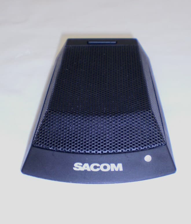
RBODS80C
Jun 19, 2013TABLETOP BOUNDARY MICROPHONE
Equipment Class
DTS - Digital Transmission System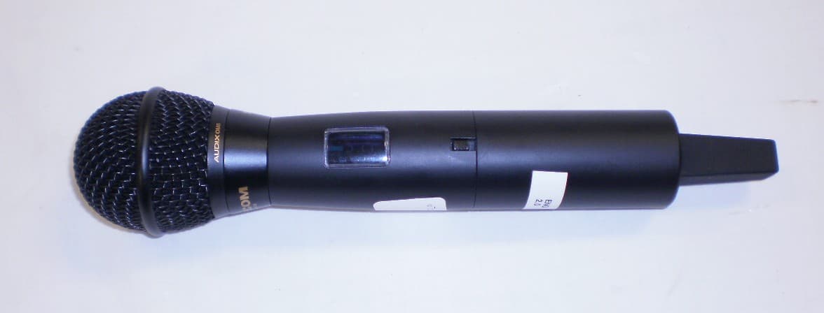
RBODS80H
Jun 11, 2013HANDHELD MICROPHONE
Equipment Class
DTS - Digital Transmission System