RBQAS597RFID Transmitter to identify adjacent accessories
AngioDynamics UK Limited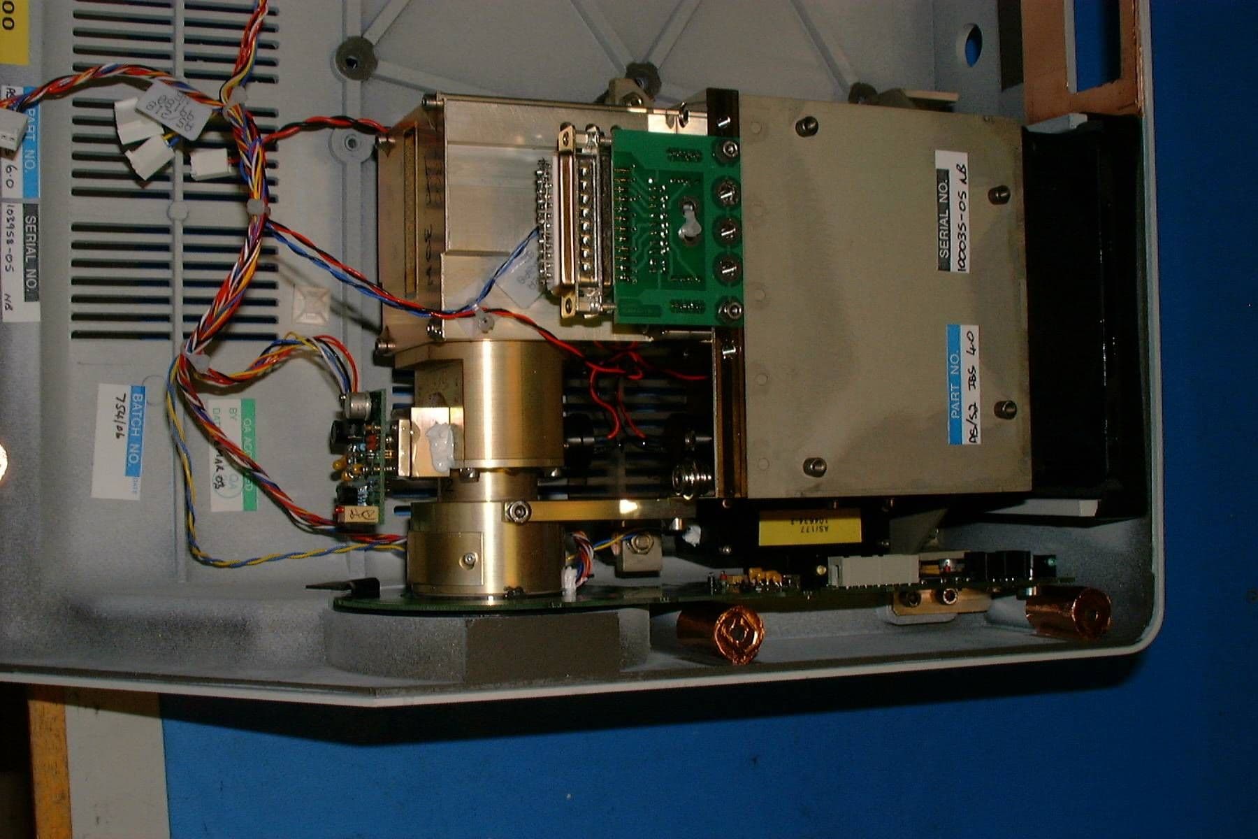
Click to zoom
Application Details
- Equipment Class
- DCD - Part 15 Low Power Transmitter Below 1705 kHz
- Date of Grant
- Sep 16, 2003
- Application Purpose
- Original Equipment
- Date of Application
- Sep 16, 2003
- Equipment Note
- RFID Transmitter to identify adjacent accessories
- Frequency Range
- 0.12500000 - 0.12500000
- Company
- AngioDynamics UK Limited
- Country
- United Kingdom
Documents & Files
Document Text
Text extracted from the exhibit documents filed with the FCC. Open a document above to read the original.
Block Diagram
CONFIDENTIAL Page 2of 4 Author: C. E. Daily. Diomed Limited 30 July 2003 AutoID Module Circuit Overview The AutoID circuit is implemented on a four-layer surface mount printed circuit board (PCB 044 issue1). One of the layers is used for +5V, and one as a ground plane. The other two are used for signals. The circuit consists essentially of a RFID base station IC, an integral PCB antenna coil, an AVR microcontroller, and a RS232 driver. See fig 1. Fig. 1 AutoID Block Diagram Connection to D15plus / D30plus Lasers The AutoID module is connected to the Laser via an RS232 port. This connection is made via an IDC connector/ribbon cable assembly. A MAX232A converts the RS232 signals to 5V logic levels for the AVR micro-controller (ATmega 8515L). 16 way IDC connection details. Pin12345678910111213141516 Function n/c n/c n/c n/c 0V n/c +12V n/c 0V n/c 0V CTS RxD RTS TxD 0V Notes: 1. n/c = no connection. 2. RTS and CTS are linked on the AutoID module. RS232 DRIVER IC Atmel AVR Micro- controller Atmel 2270B RFID BASE STATION Reset Generator Antenna (PCB Coil) 16 Way IDC 10 Way IDC 5V Regulator 8V Regulator Programming Header RS232 Header (connection to Laser) Rfid Tag 125kHz
Cover Letter(s)
Page 1 of 1 Author: C.E. Daily, Diomed Limited. 30 June 2003 AS/597 RFID Module Warning Statements Warning Statements “This product complies with part 15 of the FCC Rules. Operation is subject to the following two conditions: (1) This device may not cause harmful interference, and (2) This device must accept any interference received, including interference that may cause undesired operation.” “This equipment generates, uses and can radiate radio frequency energy and, if not installed and used in accordance with the instruction manual, may cause harmful interference to radio communications.” “Operation of this equipment in a residential area may cause harmful interference in which case the user will be required to correct the interference at their expense.” “Modifications not expressly approved by the manufacturer could void the user’s authority to operate the equipment under FCC rules.” Location of warning statements: See page 4 of the “D15plus/D30plus Diode Laser User Manual Addendum”.
External Photos
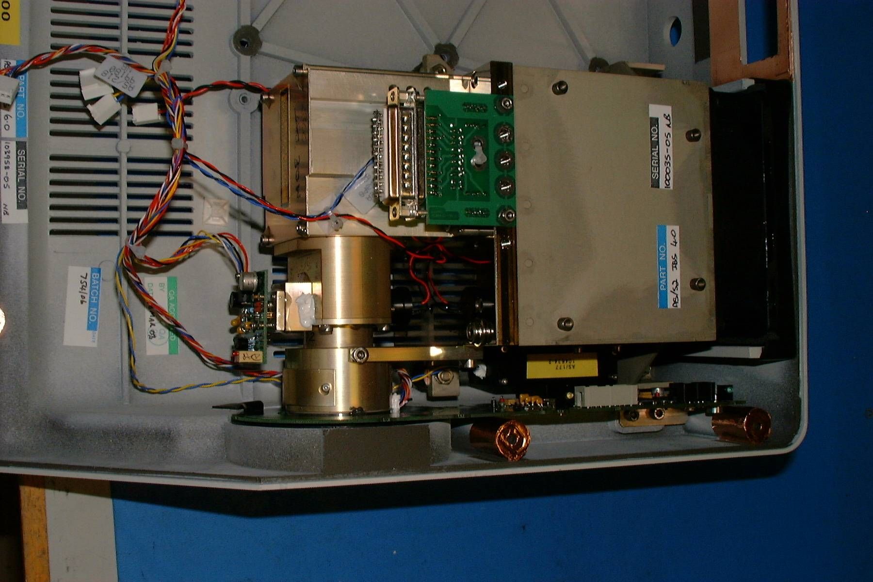
RBQAS597 External photos. Please refer to page 5 of the instruction manual and the test report.
ID Label/Location Info
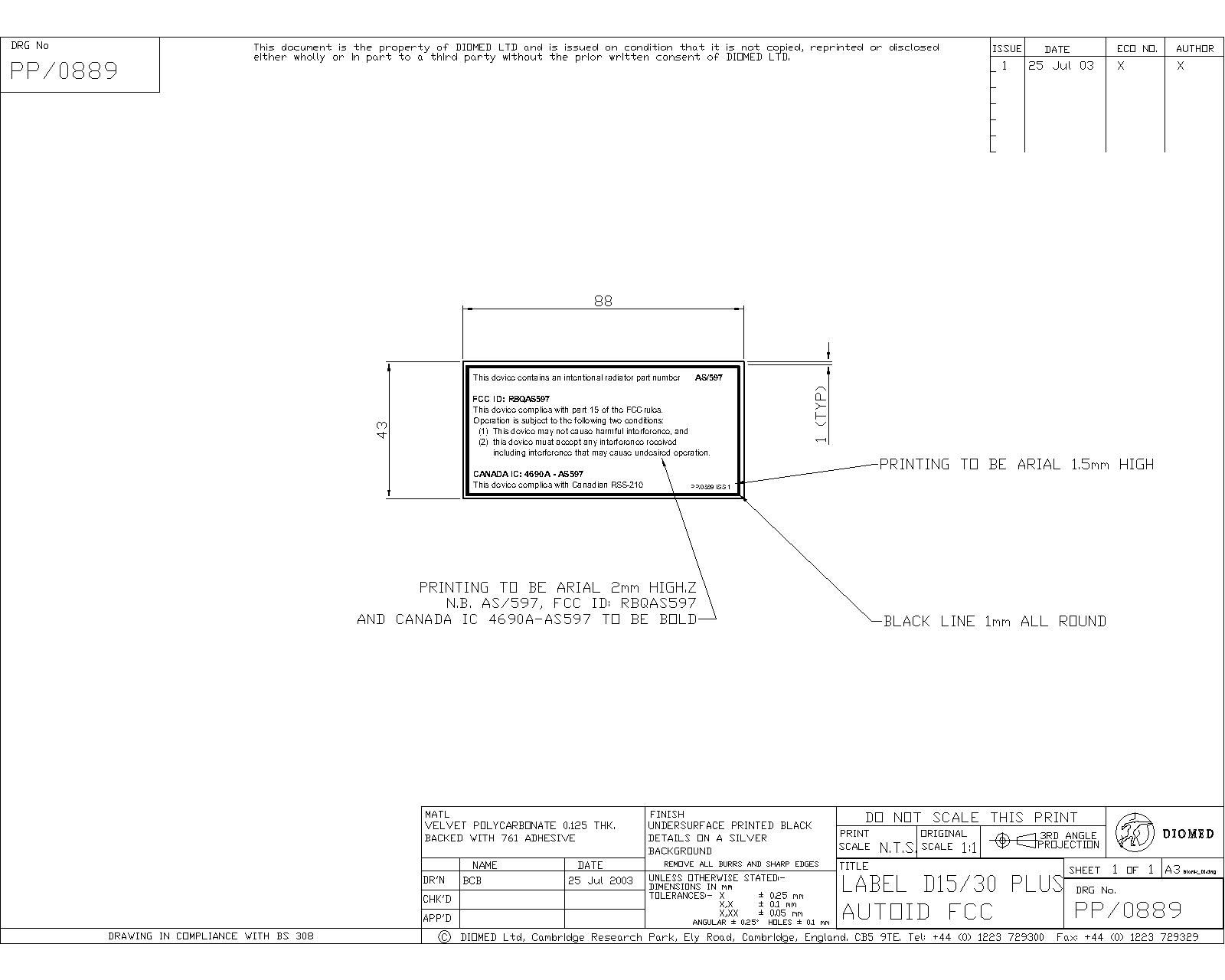
Page 1 of 1 Author: C. E. Daily, Diomed Limited 30 July 2003 AS/597 RFID Module Label Positions Label Artwork See Drawings PP/0899 Issue 1 and PP/0900 Issue 1. Position of Label PP/0900 on PCB 044 (AS/597) Position of Label PP/0889 on right hand side of D15plus and D30plus lasers. See also page 5 of the Diomed15plus / Diomed30plus Diode Laser User Manual Addendum. Label Material and Fixing: Polycarbonate, backed with permanent adhesive.
Contact Information
Applicant
Simon Jordan(Worldwide QARA Manager)
Technical Contact
Non-Technical Contact
Diomed LimitedTimothy Phipps
[email protected]+441223729300
Test Firm
DB TechnologyDave Smith
Technical Specifications
| # | Rule Parts | Frequency Range | Power Output |
|---|---|---|---|
| 1 | 15C | 0.125 MHz - 0.125 MHz | - |
Other Applications from AngioDynamics UK Limited
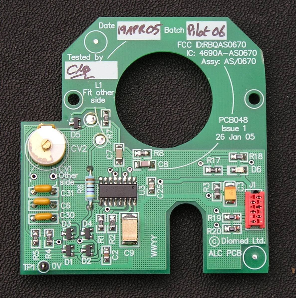
RBQAS0670
Jul 19, 2005Diomed RFID Module type AS/0670
Equipment Class
DCD - Part 15 Low Power Transmitter Below 1705 kHz