RBSSCC200Radio Frequency Identification System Equipment
Shanghai Shenchang Electronics Technology Co., Ltd.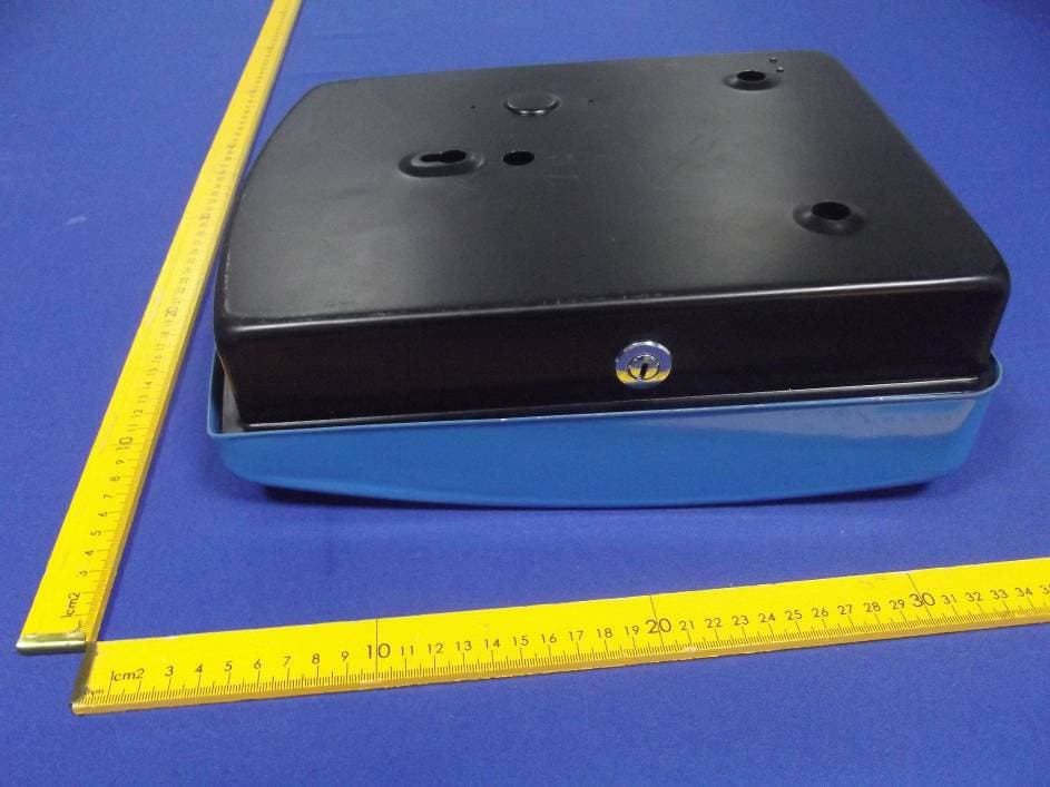
Click to zoom
Application Details
- Equipment Class
- JBP - Part 15 Class B Computing Device Peripheral
- Date of Grant
- Dec 19, 2012
- Application Purpose
- Original Equipment
- Date of Application
- Dec 19, 2012
- Equipment Note
- Radio Frequency Identification System Equipment
- Country
- China
Documents & Files
Document Text
Text extracted from the exhibit documents filed with the FCC. Open a document above to read the original.
Users Manual
FCC ID: RBSSCC200 FCC INFORMATION This device complies with Part 15 of the FCC Rules. Operation is subject to the following two conditions: 1. This device may not cause harmful interference, and 2. This device must accept any interference received, including interference that may cause undesired operation. Note: This equipment has been tested and found to comply with the limits for a Class B digital device, pursuant to part 15 of the FCC Rules. These limits are designed to provide reasonable protection against harmful interference in a residential installation. This equipment generates, uses and can radiate radio frequency energy and, if not installed and used in accordance with the instructions, may cause harmful interference to radio communications. However, there is no guarantee that interference will not occur in a particular installation. If this equipment does cause harmful interference to radio or television reception, which can be determined by turning the equipment off and on, the user is encouraged to try to correct the interference by one or more of the following measures: —Reorient or relocate the receiving antenna. —Increase the separation between the equipment and receiver. —Connect the equipment into an outlet on a circuit different from that to which the receiver is connected. —Consult the dealer or an experienced radio/TV technician for help. Caution: Any changes or modifications not expressly approved by the party responsible for compliance could void the user's authority to operate this equipment.
Users Manual
SCC 200 Introduction The intelligent controller,SCC200, provides lots of new features. First of all it features programmability to increase flexibility thus gives better performance and stability to the specific applications and more opportunity to broader application areas. The SCC200 may be easily configured to support different environment, or change parameters. It also supports multiple input/output ports in addition to communication interface. Furthermore, three general purpose UARTs may be configured and programmed to meet customer’s specific requirements which gives customers greater flexibility and values. Product Features Processor: 32bit ARM Cortex M3,100MHz Memory: 32M bits Recording capacity: 100000 RTC: Yes Backup Battery: Yes LCD Pixels: 128*64 KeyBoard: 4*4 Operating Voltage: DC12V Power consumption: 5W(max) Communication interface: RS-485; RS-232; Uart; IIC RS485 Rate: 19200bps(9600~115200bps Adjust) Operating temperature: -40°C to +85°C Storage temperature: -40°C to +125°C Humidity: < 90% IEC 60068-2-30 Interface Descriptions 1、Power Supply It must be connected to external DC power for supplying voltage to main board and LCM. The voltage is acceptable from 9V to 15V. 2、RS485 Interface The SCC200 can be connected to external communication device such as The SCR100 reader via RS485 bus cable. Default baud rate is 19200bps. 3、IIC Interface The SCC200 can be connected to LCM via IIC bus cable. The max clock frequency is 400kHz. 4、JTAG Interface Debug and trace functions are integrated into the SCC200. Serial wire debug and trace functions are supported in addition to a standard JTAG debug and parallel trace functions. Installation and using 1、Power Distribution Unit Before installation, check according to the design drawing for the following items: the model No. and specification of the input power voltage operation and display console; the condition and integrity of the electric components inside of the cable connections. Check the following items according to the electric wiring diagram: if the wirings are correct; if the plug-in units are well connected and if the connections are secure and reliable. 2、Voltage power supply The DC input power connector is as follows: 3、Keyboard Information The keyboard assignment is as follows: 123 456 789 0*# ▲ ▲ OK Keyboard Functions: 0~9 * # OK number dot reserved Enter return up down 4、Main Menu Show No. System Menu Description 1. Set Device ID Such as 10001 (max 18 bits) 2. Set Phone Call No Such as 18609830987 3. Set Main IP Such as 146.079.126.155 (3303) 4. Set Backup IP Such as 146.079.126.156 (3303) 5. Set Reader ID 1:Outside; 2:Inside 6. Request Reader Version 1:ID1; 2:ID2 7. Request Reader Gain 1:ID1; 2:ID2 8. Set Reader Gain Set gain from 0 to 31 9. Set Reader Buzzer Set Buzzer On/Off 10. Set Phone Call Time 0-30 minute 11. Request Record Info Show System Running Info 12. Init System 1:del record 2:restore system config 13. Modify login pin Modify New System login pin 14. Restart System Reset System 5、Safety Ensure the system works normally and is free from any damage or incorrect manipulation. Shutdown all of the voltage power sources fall when repair or inspection is being conducted. Applications Access Control Electronic Toll Collection (ETC) Automatic Vehicle Identification Assets Management Retail
External Photos
FCC ID: RBSSCC200 Page 15 o f 19 Anbotek Compliance Laboratory Limited Report No. 201211824F AppendixI(External Photos) Figure 1 The EUT-Overall View Figure 2 The EUT-Back View FCC ID: RBSSCC200 Page 16 o f 19 Anbotek Compliance Laboratory Limited Report No. 201211824F Figure 3 The EUT-Side View
ID Label/Location Info
Label and Label location FCC ID: RBSSCC200 This device complies with Part 15 of the FCC Rules. Operation is subject to the following two conditions: 1. This device may not cause harmful interference, and 2. This device must accept any interference received, including interference that may cause undesired operation.
Internal Photos
FCC ID: RBSSCC200 Page 17 o f 19 Anbotek Compliance Laboratory Limited Report No. 201211824F Appendix II (Internal Photos) Figure 4 The EUT-Inside View Figure 5 PCB of the EUT-Front View FCC ID: RBSSCC200 Page 18 o f 19 Anbotek Compliance Laboratory Limited Report No. 201211824F Figure 6 PCB of the EUT-Back View Figure 7 PCB of the EUT-Front View FCC ID: RBSSCC200 Page 19 o f 19 Anbotek Compliance Laboratory Limited Report No. 201211824F Figure 8 PCB of the EUT-Back View Figure 9 PCB of the EUT-Back View
Test Report
FCC ID: RBSSCC200 Page 1 o f 19 Anbotek Compliance Laboratory Limited Report No. 201211824F FCC TEST REPORT for Shanghai Shenchang Electronics Technology Co., Ltd. Radio Frequency Identification System Equipment Model No.: SCC200\CSR100\SCT120 Prepared for : Shanghai Shenchang Electronics Technology Co., Ltd. Address : Room 806, Area C, 666 Beijing East Road, Shanghai Prepared By : Anbotek Compliance Laboratory Limited Address : 1/F, 1 /Building, SEC Industrial Park, No. 4 Qianhai Road, Nanshan District, Shenzhen, 518054, China Tel: (86) 755-26066544 Fax: (86) 755-26014772 Report Number : 201211824F Date of Test : Nov. 27 to Dec. 04, 2012 Date of Report : Dec. 04, 2012 FCC ID: RBSSCC200 Page 2 o f 19 Anbotek Compliance Laboratory Limited Report No. 201211824F TABLE OF CONTENTS Description Page Test Report 1. GENERAL INFORMATION ............................................................................................................... 4 1.1. Description of Device (EUT) ..........................................................................................................................4 2. POWER LINE CONDUCTED MEASUREMENT ........................................................................... 5 2.1. Test Equipment ...............................................................................................................................................5 2.2. Block Diagram of Test Setup ..........................................................................................................................5 2.3. Power Line Conducted Emission Measurement Limits (FCC Part 15 Class B) .............................................5 2.4. Configuration of EUT on Measurement..........................................................................................................6 2.5. Operating Condition of EUT...........................................................................................................................6 2.6. Test Procedure.................................................................................................................................................6 2.7. Power Line Conducted Emission Measurement Results.................................................................................6 3. RADIATED EMISSION MEASUREMENT...................................................................................... 9 3.1. Test Equipment ...............................................................................................................................................9 3.2. Block Diagram of Test Setup ..........................................................................................................................9 3.3. Radiated Emission Limit (Subpart B Class B) ..............................................................................................10 3.4. EUT Configuration on Measurement ............................................................................................................10 3.5. Operating Condition of EUT.........................................................................................................................10 3.6. Test Procedure...............................................................................................................................................10 3.7. Radiated Emission Measurement Results .....................................................................................................11 4. PHOTOGRAPH .................................................................................................................................. 14 4.1. Photo of Power Line Conducted Emission Test............................................................................................14 4.2. Photo of Radiated Emission Test ..................................................................................................................14 AppendixI(External Photos) (2 pages) Appendix II (Internal Photos) (3 pages) FCC ID: RBSSCC200 Page 3 o f 19 Anbotek Compliance Laboratory Limited Report No. 201211824F TEST REPORT Applicant : Shanghai Shenchang Electronics Technology Co., Ltd. Manufacturer : Shanghai Shenchang Electronics Technology Co., Ltd. EUT : Radio Frequency Identification System Equipment Model No. : SCC200\CSR100\SCT120 Rating : AC 120V/60Hz Trade Mark : N.A. Measurement Procedure Used: FCC Rules and Regulations Part 15 Subpart B 2011 & FCC / ANSI C63.4-2009 The device described above is tested by Anbotek Compliance Laboratory Limited To determine the maximum emission levels emanating from the device. The maximum emission levels are compared to the FCC Part 15 Subpart B Class B limits both radiated and conducted emissions. The measurement results are contained in this test report and Anbotek Compliance Laboratory Limited Is assumed full responsibility for the accuracy and completeness of these measurements. Also, this report shows that the Equipment Under Test (EUT) is to be technically compliant with the FCC requirements. This report applies to above tested sample only. This report shall not be reproduced in part without written approval of Anbotek Compliance Laboratory Limited Date of Test : Nov. 27 to Dec. 04, 2012 Prepared by : (Tested Engineer / Rock Zeng ) Reviewer : (Project Manager / Andy Chen ) Approved & Authorized Signer : (Manager / Tom Chen) FCC ID: RBSSCC200 Page 4 o f 19 Anbotek Compliance Laboratory Limited Report No. 201211824F 1. GENERAL INFORMATION 1.1. Description of Device (EUT) Description : Radio Frequency Identification System Equipment Model Number : SCC200\CSR100\SCT120 Test Power Supply : AC 120V/60Hz Applicant : Shanghai Shenchang Electronics Technology Co., Ltd. Address : Room 806, Area C, 666 Beijing East Road, Shanghai Manufacturer : Shanghai Shenchang Electronics Technology Co., Ltd. Address : Room 806, Area C, 666 Beijing East Road, Shanghai Date of Sample received : Nov. 27, 2012 Date of Test : Nov. 27 to Dec. 04, 2012 FCC ID: R…
Text truncated - open the document above for the full version.
Test Setup Photos
FCC ID: RBSSCC200 Page 14 o f 19 Anbotek Compliance Laboratory Limited Report No. 201211824F 4. PHOTOGRAPH 4.1. Photo of Power Line Conducted Emission Test 4.2. Photo of Radiated Emission Test
Contact Information
Applicant
Yang Bo(General manager)
Technical Contact
Test Firm
Shenzhen Anbotek Compliance Laboratory LimitedDaniel zhu
[email protected]86-755-26014771
Technical Specifications
| # | Rule Parts | Frequency Range | Power Output |
|---|---|---|---|
| 1 | 15B | - | - |