RBT99061003Ground Penetrating Radar System
PipeHawk Plc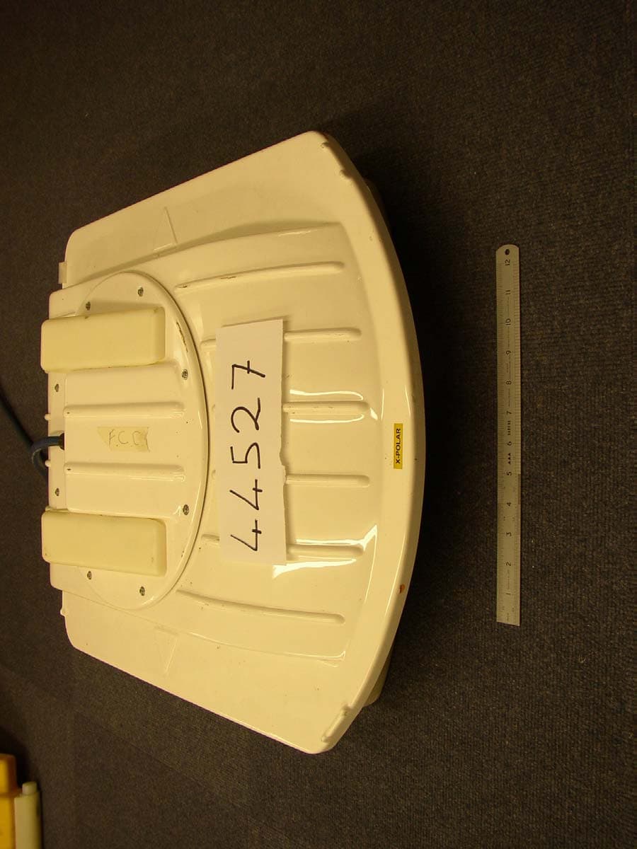
Click to zoom
Application Details
- Equipment Class
- UWB - Ultra Wideband Transmitter
- Date of Grant
- Mar 30, 2004
- Application Purpose
- Original Equipment
- Date of Application
- Jul 30, 2003
- Equipment Note
- Ground Penetrating Radar System
- Frequency Range
- 128.83000000 - 764.04000000
- Company
- PipeHawk Plc
- Country
- United Kingdom
Documents & Files
Document Text
Text extracted from the exhibit documents filed with the FCC. Open a document above to read the original.
Users Manual
PipeHawk Operator’s Manual 100049000-C PipeHawk Mk 2 Pipe Locator System Ground Penetrating Radar System Operator’s Manual – Metric P IPE H AWK PLC Systems House, Mill Lane, Alton, Hampshire, GU34 2QG, United Kingdom Tel: +44 (0) 1420 590990, Fax: +44 (0) 1420 590920, e-mail: [email protected], Web Site: www.pipehawk.com PipeHawk Operator’s Manual 100049000-C C OPYRIGHT PipeHawk (Patent applied for) COPYRIGHT EMRAD LIMITED 1994, 1995, 1999, and 2000 COPYRIGHT PIPEHAWK PLC 2000 All Rights Reserved This manual and the Software and Hardware described in it are copyright with all rights reserved. No part of this publication may be reproduced, transmitted transcribed, stored in a retrieval system or translated into any language in any form by any means without the written permission of PIPEHAWK PLC. Brand names, company names and product names are trademarks or registered trademarks of their respective companies, and are fully acknowledged. Whilst every care has been taken in preparing this document to ensure that the information herein is correct as at the time of publication, no warranties or representations are given nor implied thereby and no use is authorised in respect of this document except for the specific purposes for which it has been supplied. This document does not form part of or constitute any offer or contract with PIPEHAWK PLC unless attached to and expressly stated to be incorporated therein. PIPEHAWK PLC reserves the right to revise and improve its products as it sees fit. Compliance with Manufacturer's Design - Modification Warning Changes or modifications not expressly approved by the party responsible for compliance could void the user's authority to operate the equipment. Radio Licensing Notice The users of UWB imaging devices shall supply operational areas to the FCC Office of Engineering and Technology, which shall coordinate this information with the Federal Government through the National Telecommunications and Information Administration. The information provided by the UWB operator shall include the name, address and other pertinent contact information of the user, the desired geographical area(s) of operation, and the FCC ID number and other nomenclature of the UWB device. If the imaging device is intended to be used for mobile applications, the geographical area(s) of operation may be the state(s) or county (ies) in which the equipment will be operated. The operator of an imaging system used for fixed operation shall supply a specific geographical location or the address at which the equipment will be operated. This material shall be submitted to Frequency Coordination Branch, OET, Federal Communications Commission, 445 12th Street, SW, Washington, DC 20554, Attn UWB Coordination. © PipeHawk plc 2003 Page ii PipeHawk Operator’s Manual 100049000-C R ECORD OF R EVISIONS REVISION DATE CHANGE NAME A 11 April 2000 First Release R J CHIGNELL B 14 December 2000 Amendment of Section 4.3 R J CHIGNELL C 10 July 2003 FCC Radio Licensing Notice Added R J CHIGNELL © PipeHawk plc 2003 Page iii PipeHawk Operator’s Manual 100049000-C C ONTENTS C OPYRIGHT ............................................................................................................................................................ II R ECORD OF R EVISIONS .......................................................................................................................................... II C ONTENTS ............................................................................................................................................................. IV PREFACE ................................................................................................................................................................1 1.0 I NTRODUCTION .............................................................................................................................................2 2.0 T ECHNICAL S PECIFICATION ........................................................................................................................3 2.1 R ADAR S YSTEM ........................................................................................................................................3 2.2 T ECHNICAL S PECIFICATION ......................................................................................................................5 2.2.1 Operating and Storage Conditions.................................................................................................5 2.2.2 Mechanical Data............................................................................................................................5 2.2.3 Tyres...............................................................................................................................................5 2.2.4 Electrical Power Requirement........................................................................................................5 2.2.5 Detection.........................................................................................................................................5 2.2.6 Screen .............................................................................................................................................5 2.2.7 Construction ...................................................................................................................................5 2.2.8 Down Loading Measurement Data .................................................................................................6 3.0 M AINTENANCE AND C ARE OF P IPE H AWK ...................................................................................................7 3.1 C ARE OF P IPE H AWK .................................................................................................................................. 7 3.2 T HE A NTENNA W EAR M EMBRANE ........................................................................…
Text truncated - open the document above for the full version.
Cover Letter(s)
PipeHawk plc Systems House Mill Lane Alton HampshireGU34 2QG 13 th August 2003 Federal Communications Commission, FCC Application Processing Branch, Reference FCC ID RBT99061003 Applicant PipeHawk plc Correspondence Reference Number 25574 731 Confirmation Number EA540369 In response to a request by Linda Elliott for the submission of a sketch or photograph showing where the identification label will be placed on the device, pursuant to Section 2.1033(b) (7) of the FCC Rules, at 05:02:18 on Wednesday August 13, 2003, an additional submission was made of an external photograph showing the position of the proposed label. Yours faithfully, Richard J Chignell
Cover Letter(s)
Re: FCC ID RBT99061003 Applicant: PipeHawk Plc Correspondence Reference Number: 26325 731 Confirmation Number: EA540369 Quote: “1. You state that the ground plane is beneath the concrete slabs during tests. The photo’s show this also. Remove these slabs and place a 20 inch bed of sand beneath the EUT. Do not put any ground plane beneath the device, remove it. Please retest. Please keep in mind the following and also past measurement issues.” Response: I can confirm that the EUT was placed on a 20 inch bed of sand. The bed of sand was placed on a protective layer of none conductive stone slabs. The slabs are used to protect the ground plane. The ground plane is none removable and was used in line with the FCC’s own guidelines as stipulated by the FCC in there First Report and Order Docket 98-153 Appendix F (7) which states “Field strength measurements may be performed without the use of a ground plane; however, a factor of 4.7 dB must be added to the measurement results thus obtained.” This implies a ground plane may be used without the addition of 4.7 dB. The stone slabs serve the purpose of protection for the ground and have no direct effect on the final result. The measurement is made in compliance with C63.4 5.4 & 5.5. The site attenuation also fits within the specified criteria of C63.4 5.4.6.3 confirming the lack of influence the slabs have on the final result. Please see the following graphs showing the NSA. Graph 1: NSA - Horizontal Polarization. Graph 2: NSA - Vertical Polarization. Quote: “2. Verify the type of Average detector used for making average measurements. Ensure/verify that RMS average is used. The proper integration time is required. You state that CISPR 16-1 is used. This is a measurement standard. Use a RMS detector not an average detector for measurements above 1 GHz and show and explain how the integration time is properly set.” Response: I can confirm that an RMS average detector was used and that its characteristics are as detailed within CISPR 16-1.in the section on CISPR measurement receiver characteristics. Quote: “3. State the pulse width of the device. Ensure that this agrees with the manufacturers specification.” Response: Please see previous correspondence for appropriate response. Quote: “4. A high gain amplifier was not listed in the measurement instrument list. This is required for these measurements to obtain enough sensitivity especially for measurements for 15.509(e). Please explain/correct. Response: Please see previous correspondence for appropriate response. Quote: “5 Page 29 o f 32 still states that different detectors were used when measuring the UWB bandwidth. Quasi peak measurements were made below 1 GHz and peak above 1 GHz. Use peak for below and above 1 GHz and use the same RBW to measure the UWB bandwidth. Please explain/correct or retest accordingly as requested previously.” Response: I can confirm that page 29 states peak detector only. Here is a quote to the reference in the report that was sent too you “The Ultra Wide Bandwidth was measured using a peak detector”. There are no additional references to detector types on page 29.
Cover Letter(s)
Dear Sir Please find below the answers to your line of questions. I hope they meet with your satisfaction. 1) I would like to confirm that the ground plane is in fact beneath the concrete slabs when testing was performed. However, these concrete slabs were in place to protect the ground plane in the Open Area Test Site. Therefore, it will not be necessary to take into account the 4.7dB correction factor. 2) see test report. 3) see test report. (We confirm the average detector characteristics are as per CISPR 16-1) 4) This information must be gleaned from the manufacturers data sheets. This is not a test called up by the technical standards. 5) The reason why no pre-amplifier was used, was because a 10dB pre-amplifier was already incorporated within the spectrum analyser. There was sufficient margin between the limit line. 6) FCC Part 15.509(e) states: In addition to the radiated emission limits specified in the table in paragraph (d) of this section, UBW transmitters operating under the provisions of this section shall not exceed the following average limits when measured using a resolution bandwidth of no less than 1 kHz. - Therefore a resolution bandwidth of greater than 1 kHz was used as allowed. 7) see test report. 8) see test report. 9) All intended emissions within 10dB of the peak were taken into account in the UBW bandwidth test. Those emissions within 10dB not taken into account were in fact spurious emissions. 10) The data does not show peak levels of the EUT operating in standby mode. These were in fact taken while the EUT was transmitting. However, taking into consideration the emission bandwidth that the EUT operates over, these peak emission levels were obtained by reducing the frequency span of the analyser at the frequency which maximum level can be found. 11) see test report. 12) see test report.
Cover Letter(s)
Re: FCC ID RBT99061003 Applicant: PipeHawk Plc Correspondence Reference Number: 26325 731 Confirmation Number: EA540369 Quote: “1. You state that the ground plane is beneath the concrete slabs during tests. The photo’s show this also. Remove these slabs and place a 20 inch bed of sand beneath the EUT. Do not put any ground plane beneath the device, remove it. Please retest. Please keep in mind the following and also past measurement issues.” Response: I can confirm that the EUT was placed on a 20 inch bed of sand. The bed of sand was placed on a protective layer of none conductive stone slabs. The slabs are used to protect the ground plane. The ground plane is none removable and was used in line with the FCC’s own guidelines as stipulated by the FCC in there First Report and Order Docket 98-153 Appendix F (7) which states “Field strength measurements may be performed without the use of a ground plane; however, a factor of 4.7 dB must be added to the measurement results thus obtained.” This implies a ground plane may be used without the addition of 4.7 dB. The stone slabs serve the purpose of protection for the ground and have no direct effect on the final result. The measurement is made in compliance with C63.4 5.4 & 5.5. The site attenuation also fits within the specified criteria of C63.4 5.4.6.3 confirming the lack of influence the slabs have on the final result. Please see the following graphs showing the NSA. Graph 1: NSA - Horizontal Polarization. Graph 2: NSA - Vertical Polarization. Quote: “2. Verify the type of Average detector used for making average measurements. Ensure/verify that RMS average is used. The proper integration time is required. You state that CISPR 16-1 is used. This is a measurement standard. Use a RMS detector not an average detector for measurements above 1 GHz and show and explain how the integration time is properly set.” Response: I can confirm that an RMS average detector was used and that its characteristics are as detailed within CISPR 16-1.in the section on CISPR measurement receiver characteristics. Quote: “3. State the pulse width of the device. Ensure that this agrees with the manufacturers specification.” Response: Please see previous correspondence for appropriate response. Quote: “4. A high gain amplifier was not listed in the measurement instrument list. This is required for these measurements to obtain enough sensitivity especially for measurements for 15.509(e). Please explain/correct. Response: Please see previous correspondence for appropriate response. Quote: “5 Page 29 o f 32 still states that different detectors were used when measuring the UWB bandwidth. Quasi peak measurements were made below 1 GHz and peak above 1 GHz. Use peak for below and above 1 GHz and use the same RBW to measure the UWB bandwidth. Please explain/correct or retest accordingly as requested previously.” Response: I can confirm that page 29 states peak detector only. Here is a quote to the reference in the report that was sent too you “The Ultra Wide Bandwidth was measured using a peak detector”. There are no additional references to detector types on page 29.
External Photos
Radio Frequency Investigation Ltd, Ewhurst Park, Ramsdell, Basingstoke, Hampshire, RG26 5RQ, ENGLAND. Tel: +44 (0) 1256 851193 Fax: +44 (0) 1256 851192 Registered in England, No. 211 7901. Registered Office: Ewhurst Park, Ramsdell, Basingstoke, Hampshire RG26 5RQ 0644 EXTERNAL PHOTOGRAPH SECTION FROM RADIO FREQUENCY INVESTIGATION LTD. Test Of: PipeHawk Plc. Ground Probing Radar. To: FCC Part 15: 2002 Section 15.509 Test Report Serial No: RFI/MPTB1/RP44292JD02A RADIO FREQUENCY INVESTIGATION LTD. External Photographs S.No: RFI/MPTB1/RP44292JD02A Conformance Testing Department Test Of: PipeHawk Plc. Ground Probing Radar. To: FCC Part 15: 2002 Section 15.509 Internal Photographs of EUT This appendix contains the following photographs: Photo Reference Number Title PHT/44292JD02/001 Front Top Display PHT/44292JD02/002 Rear Top Display PHT/44292JD02/003 Front LHS PHT/44292JD02/004 Antenna Assembly LHS PHT/44292JD02/005 Antenna Assembly RHS PHT/44292JD02/006 Antenna Assembly Front PHT/44292JD02/007 Antenna Assembly Bottom PHT/44292JD02/008 Antenna Assembly Top PHT/44292JD02/009 Antenna Assembly Overall PHT/44292JD02/010 Overall View C-polar Antenna PHT/44292JD02/011 Overall View C-polar Antenna These pages are not included in the total number of pages for this report RADIO FREQUENCY INVESTIGATION LTD. External Photographs S.No: RFI/MPTB1/RP44292JD02A Conformance Testing Department Test Of: PipeHawk Plc. Ground Probing Radar. To: FCC Part 15: 2002 Section 15.509 PHT/44292JD02/001 Front Top Display RADIO FREQUENCY INVESTIGATION LTD. External Photographs S.No: RFI/MPTB1/RP44292JD02A Conformance Testing Department Test Of: PipeHawk Plc. Ground Probing Radar. To: FCC Part 15: 2002 Section 15.509 PHT/44292JD02/002 Rear Top Display RADIO FREQUENCY INVESTIGATION LTD. External Photographs S.No: RFI/MPTB1/RP44292JD02A Conformance Testing Department Test Of: PipeHawk Plc. Ground Probing Radar. To: FCC Part 15: 2002 Section 15.509 PHT/44292JD02/003 Front LHS RADIO FREQUENCY INVESTIGATION LTD. External Photographs S.No: RFI/MPTB1/RP44292JD02A Conformance Testing Department Test Of: PipeHawk Plc. Ground Probing Radar. To: FCC Part 15: 2002 Section 15.509 PHT/44292JD02/004 Antenna Assembly LHS RADIO FREQUENCY INVESTIGATION LTD. External Photographs S.No: RFI/MPTB1/RP44292JD02A Conformance Testing Department Test Of: PipeHawk Plc. Ground Probing Radar. To: FCC Part 15: 2002 Section 15.509 PHT/44292JD02/005 Antenna Assembly RHS RADIO FREQUENCY INVESTIGATION LTD. External Photographs S.No: RFI/MPTB1/RP44292JD02A Conformance Testing Department Test Of: PipeHawk Plc. Ground Probing Radar. To: FCC Part 15: 2002 Section 15.509 PHT/44292JD02/006 Antenna Assembly Front RADIO FREQUENCY INVESTIGATION LTD. External Photographs S.No: RFI/MPTB1/RP44292JD02A Conformance Testing Department Test Of: PipeHawk Plc. Ground Probing Radar. To: FCC Part 15: 2002 Section 15.509 PHT/44292JD02/007 Antenna Assembly Bottom RADIO FREQUENCY INVESTIGATION LTD. External Photographs S.No: RFI/MPTB1/RP44292JD02A Conformance Testing Department Test Of: PipeHawk Plc. Ground Probing Radar. To: FCC Part 15: 2002 Section 15.509 PHT/44292JD02/008 Antenna Assembly Top RADIO FREQUENCY INVESTIGATION LTD. External Photographs S.No: RFI/MPTB1/RP44292JD02A Conformance Testing Department Test Of: PipeHawk Plc. Ground Probing Radar. To: FCC Part 15: 2002 Section 15.509 PHT/44292JD02/009 Antenna Assembly Overall RADIO FREQUENCY INVESTIGATION LTD. External Photographs S.No: RFI/MPTB1/RP44292JD02A Conformance Testing Department Test Of: PipeHawk Plc. Ground Probing Radar. To: FCC Part 15: 2002 Section 15.509 PHT/44292JD02/010 Overall View C-polar Antenna RADIO FREQUENCY INVESTIGATION LTD. External Photographs S.No: RFI/MPTB1/RP44292JD02A Conformance Testing Department Test Of: PipeHawk Plc. Ground Probing Radar. To: FCC Part 15: 2002 Section 15.509 PHT/44292JD02/011 Overall View C-polar Antenna
ID Label/Location Info
FCC ID : RBT99061003 This device complies with Part 15 of the FCC Rules. Operation is subject the following two conditions : (1) this device may not cause harmful interference, and (2) this device must accept any interference received, including interference that may cause undesirable operation
ID Label/Location Info
Additional Information Submitted to the FCC Re: FCC ID RBT 99061003 Applicant PipeHawk plc Correspondence Reference Number 25574 731 Confirmation Number EA540369 External Photograph showing position of FCC ID Label. External Photograph of FCC ID Label
Internal Photos
Radio Frequency Investigation Ltd, Ewhurst Park, Ramsdell, Basingstoke, Hampshire, RG26 5RQ, ENGLAND. Tel: +44 (0) 1256 851193 Fax: +44 (0) 1256 851192 Registered in England, No. 211 7901. Registered Office: Ewhurst Park, Ramsdell, Basingstoke, Hampshire RG26 5RQ 0644 INTERNAL PHOTOGRAPH SECTION FROM RADIO FREQUENCY INVESTIGATION LTD. Test Of: PipeHawk Plc. Ground Probing Radar. To: FCC Part 15: 2002 Section 15.509 Test Report Serial No: RFI/MPTB1/RP44292JD02A RADIO FREQUENCY INVESTIGATION LTD. Internal Photographs S.No: RFI/MPTB1/RP44292JD02A Conformance Testing Department Test Of: PipeHawk Plc. Ground Probing Radar. To: FCC Part 15: 2002 Section 15.509 Internal Photographs of EUT This appendix contains the following photographs: Photo Reference Number Title PHT/44292JD02/001 Tx & Rx Modules in Antenna Assembly PHT/44292JD02/002 Tx & Rx Co-polar Antennas Bottom PHT/44292JD02/003 Tx Co-polar Antennas Top PHT/44292JD02/004 Rx Co-polar Antennas Top PHT/44292JD02/005 Rx Module Board 1 Top PHT/44292JD02/006 Rx Module Board 2 Top PHT/44292JD02/007 Tx Module Board 1 Top PHT/44292JD02/008 Tx Module Board Board 2 Top PHT/44292JD02/009 Tx Board 1 & 2 Bottom PHT/44292JD02/010 Tx Board 1 & 2 Top PHT/44292JD02/011 Rx Board 1 & Top PHT/44292JD02/012 Rx Board 1 & 2 Bottom PHT/44292JD02/013 X-polar Antenna Bottom PHT/44292JD02/014 X-polar Antenna Top These pages are not included in the total number of pages for this report RADIO FREQUENCY INVESTIGATION LTD. Internal Photographs S.No: RFI/MPTB1/RP44292JD02A Conformance Testing Department Test Of: PipeHawk Plc. Ground Probing Radar. To: FCC Part 15: 2002 Section 15.509 PHT/44292JD02/001 Tx & Rx Modules in Antenna Assembly RADIO FREQUENCY INVESTIGATION LTD. Internal Photographs S.No: RFI/MPTB1/RP44292JD02A Conformance Testing Department Test Of: PipeHawk Plc. Ground Probing Radar. To: FCC Part 15: 2002 Section 15.509 PHT/44292JD02/002 Tx & Rx Co-polar Antennas Bottom RADIO FREQUENCY INVESTIGATION LTD. Internal Photographs S.No: RFI/MPTB1/RP44292JD02A Conformance Testing Department Test Of: PipeHawk Plc. Ground Probing Radar. To: FCC Part 15: 2002 Section 15.509 PHT/44292JD02/003 Tx Co-polar Antennas Top RADIO FREQUENCY INVESTIGATION LTD. Internal Photographs S.No: RFI/MPTB1/RP44292JD02A Conformance Testing Department Test Of: PipeHawk Plc. Ground Probing Radar. To: FCC Part 15: 2002 Section 15.509 PHT/44292JD02/004 Rx Co-polar Antennas Top RADIO FREQUENCY INVESTIGATION LTD. Internal Photographs S.No: RFI/MPTB1/RP44292JD02A Conformance Testing Department Test Of: PipeHawk Plc. Ground Probing Radar. To: FCC Part 15: 2002 Section 15.509 PHT/44292JD02/005 Rx Module Board 1 Top RADIO FREQUENCY INVESTIGATION LTD. Internal Photographs S.No: RFI/MPTB1/RP44292JD02A Conformance Testing Department Test Of: PipeHawk Plc. Ground Probing Radar. To: FCC Part 15: 2002 Section 15.509 PHT/44292JD02/006 Rx Module Board 2 Top RADIO FREQUENCY INVESTIGATION LTD. Internal Photographs S.No: RFI/MPTB1/RP44292JD02A Conformance Testing Department Test Of: PipeHawk Plc. Ground Probing Radar. To: FCC Part 15: 2002 Section 15.509 PHT/44292JD02/007 Tx Module Board 1 Top RADIO FREQUENCY INVESTIGATION LTD. Internal Photographs S.No: RFI/MPTB1/RP44292JD02A Conformance Testing Department Test Of: PipeHawk Plc. Ground Probing Radar. To: FCC Part 15: 2002 Section 15.509 PHT/44292JD02/008 Tx Module Board Board 2 Top RADIO FREQUENCY INVESTIGATION LTD. Internal Photographs S.No: RFI/MPTB1/RP44292JD02A Conformance Testing Department Test Of: PipeHawk Plc. Ground Probing Radar. To: FCC Part 15: 2002 Section 15.509 PHT/44292JD02/009 Tx Board 1 & 2 Bottom RADIO FREQUENCY INVESTIGATION LTD. Internal Photographs S.No: RFI/MPTB1/RP44292JD02A Conformance Testing Department Test Of: PipeHawk Plc. Ground Probing Radar. To: FCC Part 15: 2002 Section 15.509 PHT/44292JD02/010 Tx Board 1 & 2 Top RADIO FREQUENCY INVESTIGATION LTD. Internal Photographs S.No: RFI/MPTB1/RP44292JD02A Conformance Testing Department Test Of: PipeHawk Plc. Ground Probing Radar. To: FCC Part 15: 2002 Section 15.509 PHT/44292JD02/011 Rx Board 1 & Top RADIO FREQUENCY INVESTIGATION LTD. Internal Photographs S.No: RFI/MPTB1/RP44292JD02A Conformance Testing Department Test Of: PipeHawk Plc. Ground Probing Radar. To: FCC Part 15: 2002 Section 15.509 PHT/44292JD02/012 Rx Board 1 & 2 Bottom RADIO FREQUENCY INVESTIGATION LTD. Internal Photographs S.No: RFI/MPTB1/RP44292JD02A Conformance Testing Department Test Of: PipeHawk Plc. Ground Probing Radar. To: FCC Part 15: 2002 Section 15.509 PHT/44292JD02/013 X-polar Antenna Bottom RADIO FREQUENCY INVESTIGATION LTD. Internal Photographs S.No: RFI/MPTB1/RP44292JD02A Conformance Testing Department Test Of: PipeHawk Plc. Ground Probing Radar. To: FCC Part 15: 2002 Section 15.509 PHT/44292JD02/014 X-polar Antenna Top
Test Report
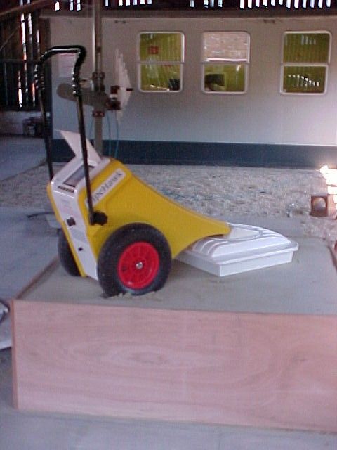
Radio Frequency Investigation Ltd, Ewhurst Park, Ramsdell, Basingstoke, Hampshire, RG26 5RQ, ENGLAND. Tel: +44 (0) 1256 851193 Fax: +44 (0) 1256 851192 Registered in England, No. 211 7901. Registered Office: Ewhurst Park, Ramsdell, Basingstoke, Hampshire RG26 5RQ 0644 TEST REPORT FROM RADIO FREQUENCY INVESTIGATION LTD. Test Of: PipeHawk plc. Ground Probing Radar To: FCC Part 15: 2002, Section 15.509 Test Report Serial No: RFI/MPTB3/RP45398JD01A Supersedes Test Report Serial No: RFI/MPTB1/RP44292JD04A, RFI/MPTB2/RP44292JD04A and RFI/MPTB1/RP45398JD01A This Test Report Is Issued Under The Authority Of Richard Jacklin, Operations Director: Checked By: Alan McHale Tested By: Release Version No: PDF01 Issue Date: 04 February 2004 Test Dates: 10 April 2003 to 14 April 2003 and 18 September 2003 This report may be reproduced in full. Partial reproduction may only be made with the written consent of Radio Frequency Investigation Ltd. The results in this report apply only to the sample(s) tested. RADIO FREQUENCY INVESTIGATION LTD. TEST REPORT S.No: RFI/MPTB3/RP45398JD01A Page 2 of 34 Issue Date: 04 February 2004 Test Of: PipeHawk plc. Ground Probing Radar To: FCC Part 15: 2002, Section 15.509 This page has been left intentionally blank. RADIO FREQUENCY INVESTIGATION LTD. TEST REPORT S.No: RFI/MPTB3/RP45398JD01A Page 3 of 34 Issue Date: 04 February 2004 Test Of: PipeHawk plc. Ground Probing Radar To: FCC Part 15: 2002, Section 15.509 Table of Contents 1. Client Information..........................................................................................................4 2. Equipment Under Test (EUT) .......................................................................................5 3. Test Specification, Methods And Procedures ............................................................8 4. Deviations From The Test Specification ...................................................................10 5. Operation Of The EUT During Testing ......................................................................11 6. Summary Of Test Results...........................................................................................12 7. Measurements, Examinations And Derived Results................................................13 8. Measurement Uncertainty ..........................................................................................23 Appendix 1. Test Equipment Used ................................................................................24 Appendix 2. Measurement Methods ..............................................................................25 Appendix 3. Test Configuration Drawings....................................................................31 Appendix 4. Graphical Test Results ..............................................................................33 Test Report Serial No: RFI/MPTB3/RP45398JD01A Supersedes Test Report Serial No: RFI/MPTB1/RP44292JD04A, RFI/MPTB2/RP44292JD04A and RFI/MPTB1/RP45398JD01A. RADIO FREQUENCY INVESTIGATION LTD. TEST REPORT S.No: RFI/MPTB3/RP45398JD01A Page 4 of 34 Issue Date: 04 February 2004 Test Of: PipeHawk plc. Ground Probing Radar To: FCC Part 15: 2002, Section 15.509 1. Client Information Company Name: PipeHawk plc Address: Systems House Mill Lane Alton Hampshire GU34 2QG United Kingdom Contact Name: Dr. R Chignell RADIO FREQUENCY INVESTIGATION LTD. TEST REPORT S.No: RFI/MPTB3/RP45398JD01A Page 5 of 34 Issue Date: 04 February 2004 Test Of: PipeHawk plc. Ground Probing Radar To: FCC Part 15: 2002, Section 15.509 2. Equipment Under Test (EUT) The following information (with the exception of the Date of Receipt) has been supplied by the client: 2.1. Identification Of Equipment Under Test (EUT) Brand Name: PipeHawk Model Name or Number: PipeHawk Unique Type Identification: None stated Serial Number: 101023039 FCC ID Number: RBT99061003 Country of Manufacture: UK Date of Receipt: 10 April 2003 and 17 September 2003 Brand Name: PipeHawk Model Name or Number: Co-Polar Antenna Unique Type Identification: None stated Serial Number: 101023186 Country of Manufacture: UK Date of Receipt: 10 April 2003 and 17 September 2003 Brand Name: PipeHawk Model Name or Number: Cross-Polar Antenna Unique Type Identification: None stated Serial Number: 101023123 Country of Manufacture: UK Date of Receipt: 10 April 2003 and 17 September 2003 2.2. Description Of EUT The equipment under test is a ground probing radar that radiates downwards to detect and map the position of buried pipes and cables. It radiates a pulse, which is only normally triggered by the forward motion of the devices; the operator pushes it forwards or backwards. The device is offered with two antennas. Both types have a dedicated pulse generator acting as the transmitter. The Co-Polar Antenna provides greater depth penetration into the ground. The Cross-Polar design provides greater resolution at shallower depths. RADIO FREQUENCY INVESTIGATION LTD. TEST REPORT S.No: RFI/MPTB3/RP45398JD01A Page 6 of 34 Issue Date: 04 February 2004 Test Of: PipeHawk plc. Ground Probing Radar To: FCC Part 15: 2002, Section 15.509 2.3. Modifications Incorporated In EUT The EUT has not been modified. 2.4. Additional Information Related To Testing Power Supply Requirement: Internal battery supply of 24 V Intended Operating Environment: Residential, Commercial Equipment Category: Mobile Type of Unit: Ground Probing Radar Weight: Approx 15 kg Dimensions: 1014 x 1796 x 575 mm Handle Extended Interface Ports: None Transmit Frequency Range 120 MHz to 960 MHz (Broadband) Co-Polar: 579.8 MHz Occupied Bandwidth Cross-Polar: 578.8 MHz RADIO FREQUENCY INVESTIGATION LTD. TEST REPORT S.No: RFI/MPTB3/RP45398JD01A Page 7 of 34 Issue Date: 04 February 2004 Test Of: PipeHawk plc. Ground Probing Radar To: FCC Part 15: 2002, Section 15.509 2.5. Support Equipment The following support equipment was used to exercise the EUT during testing: Description: Battery Charger (used to charge batteries between tests…
Text truncated - open the document above for the full version.
Contact Information
Applicant
Richard Chignell(Dr)
Technical Contact
PipeHawk PlcRichard Chignell
[email protected]+44 1420 590990
Systems House · Hampshire · United Kingdom
Test Firm
RFI Global Services Ltd.Allan Hume
Technical Specifications
| # | Rule Parts | Frequency Range | Power Output |
|---|---|---|---|
| 1 | 15F | 128.83 MHz - 764.04 MHz | - |