RBXMTSMUV2MT2011Satellite Modem
Comtech EF Data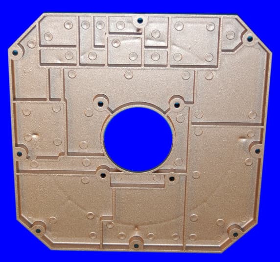
Click to zoom
Application Details
- Equipment Class
- TNB - Licensed Non-Broadcast Station Transmitter
- Date of Grant
- Apr 28, 2004
- Application Purpose
- Original Equipment
- Date of Application
- Apr 28, 2004
- Equipment Note
- Satellite Modem
- Frequency Range
- 1626.50000000 - 1645.50000000
- Company
- Comtech EF Data
- Country
- United States
Documents & Files
Document Text
Text extracted from the exhibit documents filed with the FCC. Open a document above to read the original.
Users Manual
MTS Movement Tracking System User Manual Contract No. DAAB15-99-D-0014 Revision: 1.9.1a Date: March 30, 2004 MTS Messenger V5.12 TracerLink V2.0.11 Contr act No. DAAB15-99-D-0014 MTS Users Manual Revision: 1.9.1a Page ii Version Author Date Comments 1.0 David Berger 08-31-1999 Initial Draft 1.1 Steve Line / Joe Gentile 11-17-1999 Software Changes MTS Messenger v. 1.27 TracerLink 1.5 1.2 Frank DeParis 01-31-2000 Configuration Installation Updates 1.3 Frank DeParis / Steve Line 02-29-2000 Software Changes MTS Messenger v. 1.32 TracerLink 2.0.2 1.4 Frank DeParis 03-20-2000 A-Kit Installation procedures & diagram updates Battery Pack Installation TracerLink documentation enhancements 1.5 Frank DeParis 03-23-2000 Changes per User Manual Training Scenarios Meeting Safety Section COM Port Correction Build Group PLGR & Printer Views Index Readability Test 1.5.1 Frank DeParis 03-24-2000 Fixed Version Header Date Fixed Index (V1, V2 problem) 1.6 Frank DeParis 03-30-2000 Changes per User Manual Verification at Ft. Hood 3D View of CS Laptop (Figure 3-3) New Figure 7-1 screen capture New Vehicle pictures (appendix) Upgrade Index Save Message Log Procedures (Windows Explorer instructions) Delete Message Log Procedures COM Port correction (5.2.1) Remove Readability Statistics NIMA CADRG load and view procedures Required Tools Section Transit Case Opening Procedures MTS Messenger Debug log Opening Server Vehicle Kit (7.6) 1.7 Frank DeParis 04-10-2000 Warnings Notes Expanded Index 1.8 Sandra Brown Frank DeParis 09-20-2000 Software Changes • MTS Messenger v. 1.5x • TracerLink 2.0.8 1.8.1 Frank DeParis 09-30-2000 Changes per User Manual review at Ft. Hood: • Removed references to transceiver battery pack • Add Print List capability to MTS Messenger Æ Add Group Window • Security Warning Figure 4-2 • Added FAQs 1.9 Sebastian Morana 08-13-2001 Software Changes • MTS Messenger v. 2.0.6 • Tracerlink v. 2.0.11 1.9 Richard Harer 08-13-2001 Changes per User Manual review by CASCOM and Ft. Hood • Removed chapter (s) pertaining to SatChat v 1.09 and V-1 of MTS • Updated figures to reflect upgraded software. • Added PLGR safety warning • Updated to TOC, TOF, Index 1.9.1 Richard Harer 10-01-2001 Changes per User Manual review by CASCOM and Ft. Hood • Edited Chapter 6 TOC Numbering • Updated Figures to reflect current changes 1.9.1a Dan Williamson 03-30-2004 Software Changes • MTS Messenger v 5.12 • Edited text Contr act No. DAAB15-99-D-0014 MTS Users Manual Revision: 1.9.1a Page iii Throughout this manual there are: WARNINGS, CAUTIONS and NOTES. A WARNING is a procedure which, if not followed, may result in personal injury or death. A CAUTION is a procedure which, if not followed, may result in hardware or software damage or failure. A NOTE provides the operator with additional information which provides simplification to a step or an entire procedure. WARNING ELECTRICAL SHOCK CAN RESULT IF EQUIPMENT IS OPERATED WITHOUT PROPER GROUND. DO NOT PLACE EQUIPMENT DIRECTLY ON WET GROUND, SNOW, OR ICE FOR OPERATIONS. EQUIPMENT USES POWER LINE VOLTAGE. SERIOUS INJURY OR DEATH MAY OCCUR ON CONTACT. OBSERVE SAFETY PRECAUTIONS WHEN CONTACTING POWER CABLES OR PERFORMING MAINTENANCE. BEFORE CONNECTING THE EQUIPMENT TO A POWER SOURCE, ENSURE ALL POWER SWITCHES ARE IN THE OFF POSITION. IF USING EXTENSION CORDS, ONLY USE APPROVED, HEAVY DUTY CORDS. THE PLGR WILL USE AN EXTERNAL POWER SOURCE. THE BA-5800 BATTERY WILL NOT BE USED. IMPROPER USE OF THE INTERNAL BATTERY IN CONJUNCTION WITH EXTERNAL POWER CAN RESULT IN AN EXPLOSION OF THE PLGR. Contr act No. DAAB15-99-D-0014 MTS Users Manual Revision: 1.9.1a Page iv IMPORTANT All safety precautions should be read and understood prior to deploying the MOVEMENT TRACKING SYSTEM with MT2011 or MT2010. WARNING FCC Information for Unintentional Radiator Portions as per FCC 15.19, 15.21, and 15.105. “This equipment has been tested and found to comply with the limits for Class A digital devices, pursuant to Part 15 of the FCC Rules. Those limits are designed to provide reasonable protection against harmful interference when the equipment is operated in a commercial environment. This equipment generates, uses, and can radiate radio frequency energy and, if not installed and used and used in accordance with the instruction manual, may cause harmful interference to radio communications. Operation of this equipment in a residential area is likely to cause harmful interference in which case the user will be required to correct the interference at his own expense.” WARNING Changes or modifications not expressly approved by Comtech Mobile Datacom (CMDC) could void the user’s authority to operate the equipment. WARNING FCC RF EXPOSURE INFORMATION To satisfy FCC RF exposure requirements for mobile transmitting devices, a separation distance of 40 centimeters (16 inches) or more should be maintained between the antenna of this device and persons during device operation. To ensure compliance, operation at closer than this distance is not recommended. WARNING FCC FREQUENCY COORDINATION AS PER FCC 25.203©, 25.251 and 101.103 To satisfy FCC frequency coordination requirements, the user must ensure that they co-ordinate proposed frequency and power usage with other terrestrial and satellite users prior to transmission. WARNING MICROWAVE RADIATION: HAZARDS CAUSED BY ELECTROMAGNETIC FIELDS When in operation, i.e. “power on”, the area immediately around the MT2011 or MT2010 antenna must be considered an Area of Restricted Occupancy. Limit human exposure time to the area when the Movement Tracking System with MT2011 or MT2010 is in operation. Contract No. DAAB15-99-D-0014 MTS Users Manual Revision: 1.9.1a SAFETY STEPS TO FOLLOW IF SOMEONE IS THE VICTIM OF ELECTRICAL SHOCK 1. DO NOT TRY TO PULL OR GRAB THE INDIVIDUAL. 2. IF POSSIBLE, TURN OFF THE ELECTRICAL POWER. 3. IF YOU CANNOT TURN OFF THE ELECTRICAL POWER, PULL, PUSH OR LIFT THE PERSON TO SAFETY USING A DRY WOODEN…
Text truncated - open the document above for the full version.
Users Manual
Contract No. DAAB15-99-D-0014 MTS Users Manual Revision: 1.9.1a Page 9-1 9. System Administrator Tasks 9.1 Using MTS Messenger Help Select the Help menu from the menu bar. Figure 9-1 shows the menu that will appear. Figure 9-1 Help Menu Command Reference will display the function key command reference in the display screen (see Section 5.1.1). About this Program will display the version number of the MTS Messenger program (see Section 7.2.1). I/O Logging, API Logging, and Show Debug Log all show protocol traffic to and from the satellite transceiver. The Debug Log is the only log that will be used by the System Administrator. 9.1.1 Debug Log MTS Messenger has a built-in diagnostic function, the Debug Log that may help in the event of trouble. Although this function was created for Comtech Mobile Datacom’s development engineers, a trained Army System Administrator working in conjunction with Comtech Mobile Datacom’s Support Personnel can determine some basic status information from the Debug Log. The diagnostic function displays data between the terminal and MTS Messenger and between MTS Messenger and Tracerlink. The steps below outline how to activate the Debug Log and how to interpret some of the data in the log. Again however, it is recommended that the system administrator not try to interpret this log without support from Comtech Mobile Datacom. Steps for Opening and Low-Level Interpretation of the Debug Log: (1) Select Help Æ Show Debug Log from the Help menu. When this is done, the Command displayed in the main panel will change to display diagnostic information. The diagnostic information includes all data received from and sent to the terminal, and all data sent to the Tracerlink map. Lines of the form "Army Contract No. DAAB15-99-D-0014 MTS Users Manual Revision: 1.9.1a Page 9-2 Msg of X bytes" indicate a message was received from the satellite terminal (see the red circled message in Figure 9-2). To verify the terminal is receiving messages from the satellite, view this screen for several minutes to see that messages are periodically arriving. If you receive a message, go to step 2. If you do not receive a message after 10 minutes, go to step 3. Figure 9-2 Sample Debug Log (2) To revert back to the Command Reference select Help Æ Command Reference. The Command Reference screen (also referred to as the standard MTS Messenger window) should appear as in Figure 5-5. (3) If no messages containing the string "Army Msg of X bytes:" arrive for a 10- minute period, the terminal is not receiving messages from the satellite. Check that the LED lights are illuminated (see Section 9.2). If the LED's are lit, the terminal may be blocked from satellite view by trees or buildings. Proceed to step 4. If the LED lights are not illuminated follow the procedures outlined in section 9.2. (4) Move the terminal into a clear area without any obstructions in the direction of the satellite. If the terminal has power and a view of the satellite, but is still not communicating, the terminal may be the problem, proceed to step 5. Contract No. DAAB15-99-D-0014 MTS Users Manual Revision: 1.9.1a Page 9-3 (5) At this point it will be necessary to look at the terminal directly without MTS Messenger. You will need assistance from a Comtech Mobile Datacom engineer. Please call the Comtech Mobile Datacom Support Center at 1-888-428-2101. (6) To remove the debug messages, select Help Æ Show Debug Log again. 9.2 LEDs (Light Emitting Diodes) The transceiver is equipped with three colored LEDs (light emitting diodes). The LEDs are colored Red, Yellow and Green. The LEDs are located on the side of the MT-2011 (shown in Figure 9-3) and MT-2010 terminals. Figure 9-3 LEDs on Transceiver The LEDs provide information on: Whether the terminal is receiving power. If there are no lights, the terminal is not receiving power. The transceiver startup process. The LED lights will cycle a number of times (go from Red to Yellow to Green in what appears to be a random order) during the initial startup process. Although the lighting process appears random, it actually shows the boot-up process of the firmware in the transceiver. If the terminal is functioning in standard operating mode. After the startup process, the terminal will go into its standard operating mode. During this mode the green and yellow lights will illuminate in a semi-constant fashion. Contr act No. DAAB15-99-D-0014 MTS Users Manual Revision: 1.9.1a Page 9-4 If the terminal is sending a message. The Red LED will flicker for a few milliseconds when transmitting a message. 9.2.1 No LED Lights on the Transceiver (MT-2010 and MT-2011) & Check Cables The most important indicator that the LEDs provide is whether the terminal is receiving power. If the LEDs do not turn on when a user turns on the control box, there could be one of three problems. (1) The most obvious problem would that the control box isn’t actually turned on. Turn on the control box. If this solves the problem skip all the subsequent steps. If the problem persists proceed to step 2. (2) Check to see if there are loose cables. Check that the cable to the transceiver is appropriately fastened. Ensure that the transceiver cable is not damaged at the control box. If you suspect that a cable from the control box to the transceiver has been damaged, mount the transceiver on another vehicle. Do not touch the cable if you see exposed wire. Plug in the transceiver to the other vehicle’s control box, turn on the control box and see if the transceiver’s LEDs illuminate. If the transceiver’s LEDs do not illuminate go to step 3. (3) Check the pins on connector of the transceiver. Are the pins bent or broken? Do the pins show signs of any other damage? If the answer to either of these questions is yes, contact your System Administrator, or the unit CSSAMO. If the pins appear OK, go to step 4. (4) Check to see that the control boxes you have used in steps 1-3 are functioning correctly. Try powering up another t…
Text truncated - open the document above for the full version.
Users Manual
Contract No. DAAB15-99-D-0014 MTS Users Manual Revision: 1.9.1a Page 14-1 14. Appendix 14.1 A-Kits – Vehicle Interior 14.1.1 FMTV Figure 14-1 V2 computer mount (with V2 Computer installed) inside FMTV cab 14.1.2 FMTV Control Panel Figure 14-2 V2 Control Box mounted inside FMTV cab Contract No. DAAB15-99-D-0014 MTS Users Manual Revision: 1.9.1a Page 14-2 14.1.3 HEMTT Figure 14-3 V2 computer mount (without V2 Computer) inside HEMTT cab 14.1.4 HET Figure 14-4 V2 computer mount (without V2 Computer installed) inside HET cab Contract No. DAAB15-99-D-0014 MTS Users Manual Revision: 1.9.1a Page 14-3 14.1.5 HMMWV Figure 14-5 V2 Computer Mount inside HMMWV Notice the Control Box in the center of the cab and the PLGR mounted next to the V2 computer. 14.1.6 PLS Figure 14-6 V2 Computer Mount (without V2 Computer installed) inside PLS Notice the control panel under the sliding computer mount.
Users Manual
Contract No. DAAB15-99-D-0014 MTS Users Manual Revision: 1.9.1a Page 14-9 14.3.4 V2 Computer (Screen and Keyboard) 14.3.5 V2 MIL Ports Contract No. DAAB15-99-D-0014 MTS Users Manual Revision: 1.9.1a Page 14-10 14.3.6 V2 Power and Data Cables Left to Right -- Power Cable, Data Cable Contr act No. DAAB15-99-D-0014 MTS Users Manual Revision: 1.9.1a Page 15-1 15. Index A About this Manual ........................................................ 2-3 A-Kit .............................................................................. 1-1 FMTV – Vehicle Interior ..................................................... 14-1 FMTV Transceiver Mount................................................... 14-4 HEMTT – Vehicle Interior .................................................. 14-2 HEMTT Transceiver Mount................................................ 14-4 HET – Vehicle Interior ........................................................ 14-2 HET Transceiver Mount...................................................... 14-5 HMMWV – Vehicle Interior................................................ 14-3 HMMWV Transceiver Mount............................................. 14-5 PLS – Vehicle Interior ......................................................... 14-3 PLS Transceiver Mount....................................................... 14-6 Assignments Tab (TracerLink).................................... 6-9 Autotrack (TracerLink) ............................................. 6-11 B Batteries CS Laptop Spare.............................................................3-2 B-Kit...............................................................................2-3 Bumper Number Change Bumper Number ..................................................... 5-15 Release Bumper Number ..................................................... 7-16 C CADRG (NIMA) Maps General Information ............................................................. 6-20 Loading CADRG Maps to the Computer’s Hard Drive ...... 6-24 NIMA Raster Kit Control .................................................... 6-20 Viewing CADRG Maps Directly from the Hard Drive....... 6-26 Center on Vehicle (TracerLink) ................................ 6-19 Change Center (TracerLink) ....................................... 6-6 Concept of Operations.................................................. 2-1 Control Station.............................................................. 2-3 Create Group .......................................................................... 7-1 CS Control Box ...................................................................... 4-1 Delete Group ........................................................................ 7-10 Demote Control Station ....................................................... 7-14 Equipment List ....................................................................... 3-2 Installation .............................................................................. 3-4 Picture................................................................................... 14-7 Power ON/OFF ...................................................................... 4-1 Promote Mobile Unit............................................................ 7-13 Release Bumper Number ..................................................... 7-16 CS See Control Station D Debug Log ..................................................................... 9-1 Display Position Report Time (TracerLink)............. 6-17 Displaying Individual Vehicles (TracerLink) ........... 6-15 F FMTV A-Kit -- Transceiver Mount................................................. 14-4 A-Kit -- Vehicle Interior ...................................................... 14-1 Control Panel ........................................................................14-1 G GPS (Setting the Reporting Rate) .............................. 5-14 Groups Create Group ...........................................................................7-1 Delete Group .........................................................................7-10 Hiding an Entire Group (TracerLink)...................................6-14 Modify Group .........................................................................7-6 Review Groups......................................................................5-15 Sending a Group Message......................................................5-9 Sending messages while outside of ......................................5-10 H HEMTT A-Kit -- Transceiver Mount..................................................14-4 A-Kit -- Vehicle Interior .......................................................14-2 HET A-Kit -- Transceiver Mount..................................................14-5 A-Kit -- Vehicle Interior .......................................................14-2 Hiding Groups (TracerLink)...................................... 6-14 Hiding Individual Vehicles (TracerLink) .................. 6-15 Hiding Position Report Time (TracerLink) .............. 6-17 HMMWV A-Kit -- Transceiver Mount..................................................14-5 A-Kit -- Vehicle Interior .......................................................14-3 I Icon MTS Messenger ......................................................................5-1 TracerLink Startup ..................................................................6-2 Vehicle Server.........................................................................6-2 Information Security..................................................... 2-1 Installation Control Station ........................................................................3-4 PLGR (Control Station) ..........................................................3-5 Transit Case (Opening) ...........................................................3-1 K Kit Bar (TracerLink) .................................................... 6-9 L Lat-Long Display (Changing in MTS Messenger) .... 5-12 LEDs (Ligh…
Text truncated - open the document above for the full version.
Users Manual
Contract No. DAAB15-99-D-0014 MTS Users Manual Revision: 1.9.1a Page 14-8 14.3.3 Printer Contract No. DAAB15-99-D-0014 MTS Users Manual Revision: 1.9.1a Page 14-9 14.3.4 V2 Computer (Screen and Keyboard) 14.3.5 V2 MIL Ports Contract No. DAAB15-99-D-0014 MTS Users Manual Revision: 1.9.1a Page 14-10 14.3.6 V2 Power and Data Cables Left to Right -- Power Cable, Data Cable Contr act No. DAAB15-99-D-0014 MTS Users Manual Revision: 1.9.1a Page 15-1 15. Index A About this Manual ........................................................ 2-3 A-Kit .............................................................................. 1-1 FMTV – Vehicle Interior ..................................................... 14-1 FMTV Transceiver Mount................................................... 14-4 HEMTT – Vehicle Interior .................................................. 14-2 HEMTT Transceiver Mount................................................ 14-4 HET – Vehicle Interior ........................................................ 14-2 HET Transceiver Mount...................................................... 14-5 HMMWV – Vehicle Interior................................................ 14-3 HMMWV Transceiver Mount............................................. 14-5 PLS – Vehicle Interior ......................................................... 14-3 PLS Transceiver Mount....................................................... 14-6 Assignments Tab (TracerLink).................................... 6-9 Autotrack (TracerLink) ............................................. 6-11 B Batteries CS Laptop Spare.............................................................3-2 B-Kit...............................................................................2-3 Bumper Number Change Bumper Number ..................................................... 5-15 Release Bumper Number ..................................................... 7-16 C CADRG (NIMA) Maps General Information ............................................................. 6-20 Loading CADRG Maps to the Computer’s Hard Drive ...... 6-24 NIMA Raster Kit Control .................................................... 6-20 Viewing CADRG Maps Directly from the Hard Drive....... 6-26 Center on Vehicle (TracerLink) ................................ 6-19 Change Center (TracerLink) ....................................... 6-6 Concept of Operations.................................................. 2-1 Control Station.............................................................. 2-3 Create Group .......................................................................... 7-1 CS Control Box ...................................................................... 4-1 Delete Group ........................................................................ 7-10 Demote Control Station ....................................................... 7-14 Equipment List ....................................................................... 3-2 Installation .............................................................................. 3-4 Picture................................................................................... 14-7 Power ON/OFF ...................................................................... 4-1 Promote Mobile Unit............................................................ 7-13 Release Bumper Number ..................................................... 7-16 CS See Control Station D Debug Log ..................................................................... 9-1 Display Position Report Time (TracerLink)............. 6-17 Displaying Individual Vehicles (TracerLink) ........... 6-15 F FMTV A-Kit -- Transceiver Mount................................................. 14-4 A-Kit -- Vehicle Interior ...................................................... 14-1 Control Panel ........................................................................14-1 G GPS (Setting the Reporting Rate) .............................. 5-14 Groups Create Group ...........................................................................7-1 Delete Group .........................................................................7-10 Hiding an Entire Group (TracerLink)...................................6-14 Modify Group .........................................................................7-6 Review Groups......................................................................5-15 Sending a Group Message......................................................5-9 Sending messages while outside of ......................................5-10 H HEMTT A-Kit -- Transceiver Mount..................................................14-4 A-Kit -- Vehicle Interior .......................................................14-2 HET A-Kit -- Transceiver Mount..................................................14-5 A-Kit -- Vehicle Interior .......................................................14-2 Hiding Groups (TracerLink)...................................... 6-14 Hiding Individual Vehicles (TracerLink) .................. 6-15 Hiding Position Report Time (TracerLink) .............. 6-17 HMMWV A-Kit -- Transceiver Mount..................................................14-5 A-Kit -- Vehicle Interior .......................................................14-3 I Icon MTS Messenger ......................................................................5-1 TracerLink Startup ..................................................................6-2 Vehicle Server.........................................................................6-2 Information Security..................................................... 2-1 Installation Control Station ........................................................................3-4 PLGR (Control Station) ..........................................................3-5 Transit Case (Opening) ...........................................................3-1 K Kit Bar (TracerLink) ...................................…
Text truncated - open the document above for the full version.
External Photos
BOX BOX LID LID LED VIEW LID
Internal Photos
OVERVIEW A SIDE OVERVIEW B SIDE BOARD SIDE 1A Side 1b
Operational Description
CONCEPT OF OPERATION OVERVIEW Movement Tracking System (MTS) is a global satellite communications system that provides text messaging and vehicle tracking capabilities for the U.S. Army. It allows a commander to determine where his vehicles are, what their status is, and to communicate with them in near real-time. Because the system is satellite-based, telephone lines are not required for in-theater operations, and unlike line-of-sight radios, repeater stations are never necessary. As long as the MTS satellite transceiver has an unhindered view of the satellite, it will be able to communicate with other on-line MTS systems. The three key features of the Movement Tracking System developed by Comtech Mobile Datacom (CMDC) are its ability to use a variety of in-orbit commercial satellites, its near real-time communications speed, and its security features. (1) Compatibility with Multiple Commercial Satellites The MTS system does not require proprietary satellites to function; it can use different types of commercial satellites. As a result, it provides flexibility in choosing a satellite in any region of the world. MTS-equipped vehicles can operate in all regions of the world. (2) Real-time Messaging Speeds A message is typically transmitted from one MTS-equipped vehicle to another in under 10 seconds. (3) Information Security The waveform used by Comtech Mobile Datacom’s MTS is spread spectrum and exhibits a low probability of detection by unauthorized listening devices. In addition, the data is triple encrypted end-to-end to further prevent eavesdropping. MESSAGE ROUTING ARCHITECTURE In normal operations, when an MTS user sends a message, the data packet is transmitted to the satellite, which relays it back down to the Comtech Mobile Datacom ground station switch. The switch sends the data packet back over the satellite to its intended destination. When the message is received , the destination returns an acknowledgement over the satellite to the switch, which forwards it to the message sender, verifying message delivery. USER SYSTEMS The Movement Tracking System is made up of two configurations – the Control Station, and the V2 Mobile Unit. (1) The Control Station provides command functionality for the MTS, and is typically operated from a mobile headquarters, such as a command tent or a parked van. The Control Station operates independent of phone lines or Internet connections. A Control Station operator is responsible for coordinating vehicle movements using text messaging and theater map displays of MTS-equipped vehicles. The Control Station configuration consists of a laptop computer with CE-ROM drive for NIMA map loading, a satellite transceiver with 100-foot cable, a Precision Lightweight GPS Receiver (PLGR) and a portable printer. (2) The V2 Mobile Unit is designated for permanent installation in a vehicle using an installation kit designed for that vehicle, and consists of a satellite transceiver and ruggedized computer with appropriate cabling and a Precision Lightweight GPS Receiver (PLGR). It provides text messageing and NIMA theater maps displaying MTS-equipped vehicles including own unit.
Parts List/Tune Up Info
Top Assembly,Level,Component,Short Desc,M/Purch,Comp Rev,UM,QtyPerAssy,BUYER,Mtl Cost,SoleSource,Ref Designators PL/9992,1,CN/CXLMCXFPC01,CN,P,,EA,4,6,0.78,,J600:J601:J602:J703 PL/9992,1,CN/SO-HED07MD02,CN,P,,EA,1,6,0.4,,JP1 PL/9992,1,CN/SO-HED12FD01,CN,P,,EA,1,6,1.31,,J14 PL/9992,1,CP/0603C100D,CP,P,,EA,6,6,0.013,,C315:C318:C504:C511:C585:C586 PL/9992,1,CP/0603C101J,VMI CP,P,,EA,24,4,0.004,,C138:C348:C372:C377:C422:C429:C435:C446:C452:C454:C459:C470:C510:C520 :C536:C541:C567:C588:C786:C787:C788:C789:C790:C791 PL/9992,1,CP/0603C181J,CAP,P,,EA,1,6,0.015,,C341 PL/9992,1,CP/0603C1R5C,CAP,P,,EA,3,4,0.008,,C439:C521:C568 PL/9992,1,CP/0603C220J,VMI CAP,P,,EA,6,4,0.006,,C1:C3:C5:C6:C139:C442 PL/9992,1,CP/0603C270J,CAP,P,,EA,5,4,0.01,,C342:C343:C344:C398:C399 PL/9992,1,CP/0603C2R2C,CAP,P,,EA,1,4,0.009,,C438 PL/9992,1,CP/0603C301J,CP,P,,EA,3,6,0.015,,C400:C401:C526 PL/9992,1,CP/0603C330J,VMI CP,P,,EA,58,4,0.004,,C300:C303:C306:C308:C309:C310:C320:C322:C323:C324:C331:C337:C338:C339 :C345:C353:C355:C362:C364:C367:C378:C386:C388:C389:C390:C391:C392:C393:C394:C395:C418:C428 :C434:C450:C451:C485:C486:C487:C489:C490:C491:C495:C497:C498:C514:C515:C555:C556:C573:C603 :C604:C607:C608:C609:C643:C644:C645:C648 PL/9992,1,CP/0603C390J,CAP,P,,EA,2,3,0.035,,C313:C314 PL/9992,1,CP/0603C3R3C,CAP,P,,EA,6,25,0.01,,C329:C419:C420:C440:C471:C472 PL/9992,1,CP/0603C470J,AIM CAP,P,,EA,4,4,0.015,,C518:C523:C752:C753 PL/9992,1,CP/0603C4R7C,CAP,P,,EA,2,4,0.01,,C431:C456 PL/9992,1,CP/0603C560J,CAP,P,,EA,3,4,0.01,,C517:C587:C589 PL/9992,1,CP/0603C5R6C,CP,P,,EA,2,6,0.01,,C432:C455 PL/9992,1,CP/0603C6R8C,CAP,P,,EA,2,6,0.01,,C430:C453 PL/9992,1,CP/0603C8R2C,CAP,P,,EA,4,6,0.007,,C396:C397:C525:C569 PL/9992,1,CP/0603P3R3B,CAP,P,,EA,2,6,0.51,,C443:C444 PL/9992,1,CP/0603X102K,VMI CAP,P,,EA,33,3,0.004,,C321:C330:C350:C356:C361:C379:C387:C423:C427:C436:C447:C460:C463:C47 5:C480:C505:…
Text truncated - open the document above for the full version.
Contact Information
Applicant
Paul D. Speer(PMTS Agency Compliance Engineer)
Test Firm
TUV America Inc.Jim Owen
Technical Specifications
| # | Rule Parts | Frequency Range | Power Output | Emission | Tolerance |
|---|---|---|---|---|---|
| 1 | 25 | 1.63 GHz - 1.65 GHz | 6 W | M7D | 2.5000000000 ppm |