RCB9584949 MHz WIRELESS REMOTE CONTROL CAR-TX
TOYS "R" US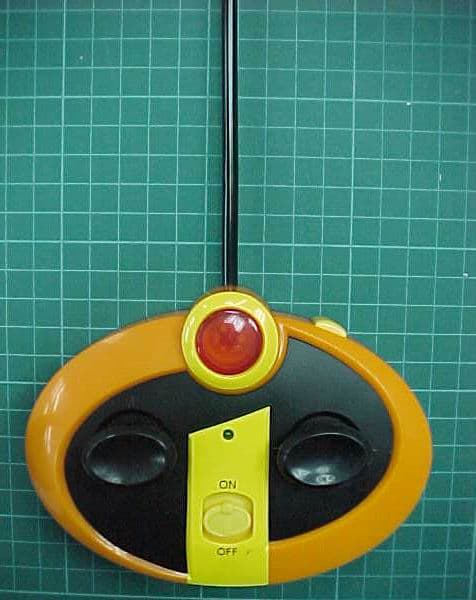
Click to zoom
Application Details
- Equipment Class
- DXX - Part 15 Low Power Communication Device Transmitter
- Date of Grant
- Aug 11, 2004
- Application Purpose
- Original Equipment
- Date of Application
- Aug 11, 2004
- Equipment Note
- 49 MHz WIRELESS REMOTE CONTROL CAR-TX
- Frequency Range
- 49.82000000 - 49.90000000
- Company
- TOYS "R" US
- Country
- United States
Documents & Files
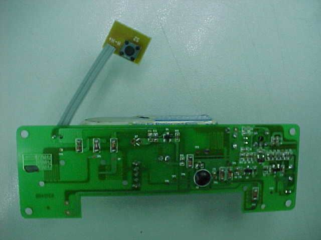
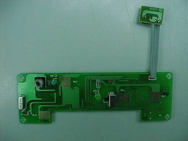
Document Text
Text extracted from the exhibit documents filed with the FCC. Open a document above to read the original.
Users Manual
(Diagram 7) (Diagram 1) (Diagram 2) (Diagram 3) (Diagram 6) (Diagram 5) Backward Forward Straight T urbo Left On Off Stop Right B F R R L L 1:16 Incredible Instruction Prints 1 Color Process BlackFolded size: 65mm x 121mmExtended size: 392mm x 121mm USING 6V BATTERY PACK:1. Slide ON/OFF switch on the bottom of the vehicle to OFF. 2. Insert battery pack into the battery compartment as shown. (See diagram 2) 3. Push battery pack forward in direction of arrow engraved on battery pack. 4. Use a coin to turn the battery compartment latch counterclockwise until it stops to lock the battery pack in position. When the vehicle slows down, recharge the battery pack. When the battery pack will no longer hold a charge, replace it.Note: To remove, use a coin to turn the battery compartment latch clockwise until it stops, slide the battery pack up and remove it from the battery compartment. © Disney / PixarF AST LANE is a mark of Geoffrey, Inc. © Geoffrey, Inc.Distributed by Toys“R”Us, Inc., W ayne, NJ 07470 Made in Chinawww.toysrus.com DRIVING THE CAR:Warning: Never play with your vehicle in the street. 1. Slide ON/OFF switch on the side of the vehicle to ON. (See diagram 5) 2. Use the transmitter’s control levers as follows: (See diagram 6) Left Control Lever:• Push forward to move forward ( F ). • Pull back to move backward ( B ). • Release to stop. Right Control Lever:• Push left to move left ( L ). • Push right to move right ( R ). • Release to go straight.TURBO:• Press "Turbo" button for maximum power. Caution: If the vehicle gets stuck under an object, immediately release the control levers on the transmitter, then retrieve the vehice.3. When you finish driving, slide the ON/OFF switch on the vehicle to OFF. HOW TO OPERATE:1. If the vehicle does not go in a straight line when you release the right control lever, adjust the wheel alignment control on the bottom of the vehicle. Turn the wheel alignment control toward L if the vehicle is pulling to the right, or toward R if the vehicle is pulling to the left. (See diagram 7) HELPFUL HINTS:The following hints can help you get the most enjoyment from your vehicle:• Running your vehicle continuously for long periods generates high heat levels. Heat causes wear and tear on the motor. When your vehicle’s battery dies, let the vehicle cool at least 10 minutes before installing a newly charged battery pack. This helps keep heat levels down. • If the vehicle’s motor runs but does not respond to the transmitter, move closer to the vehicle and try again. • If someone uses a CB nearby, it might interfere with control of the vehicle. If this happens, move the vehicle and transmitter away from the CB. • You cannot operate your vehicle near devices with transmitters that use the same frequency, (27 MHz or 49 MHz). Check the packaging to see which frequency your vehicle uses. • If the vehicle moves slowly, and you have installed a recharged battery pack, check the wheel mechanisms for lint, thread, hair or dust. CARE:The following suggestions will help you care for your vehicle so you can enjoy it for years:• Never drive the vehicle on a wet floor, on sand, or in mud, rain, or snow. These can damage it. • Do not expose the vehicle to extreme temperatures. • To protect the vehicle’s wheel mechanisms from lint and hair, do not drive it on carpet. • Occasionally wipe the vehicle with a damp cloth to keep it looking new. Do not use harsh chemicals to clean the vehicle. Modifying or tampering with the vehicle or the transmitter’s internal components can cause a malfunction and void your FCC authorization to operate them. THE FCC WANTS YOU TO KNOW:Your vehicle or transmitter might cause TV or radio interference even when it is operating properly. To determine whether your vehicle or transmitter is causing the interference, turn off your vehicle and release the transmitter’s control levers. If the interference goes away, your vehicle or transmitter is the cause.Try to eliminate the interference by:• Moving your vehicle and transmitter away from the TV or radio. If you cannot eliminate the interference, the FCC requires that you stop using your vehicle.This device complies with Part 15 of the FCC Rules. Operation is subject to the following two conditions: (1) this device may not cause harmful interference, and (2) this device must accept any interference received, including interference that may cause undesired operation. BATTERY INSTALLATION:TRANSMITTER:The transmitter requires one 9-volt battery (not included). For the best performance and longest life, we recommend an alkaline battery.Follow these steps to install the battery in the transmitter:1. Remove battery compartment cover by sliding it in the direction of the arrow shown on the compartment cover. 2. Place battery in the compartment according to the polarity symbols (+ and -) marked inside. (See diagram 1) 3. Replace the cover and snap it shut.When the transmitter’s range decreases, replace battery.CAR:Your vehicle requires a 6-volt rechargeable battery pack (not included) or 4 x AA batteries (not included). 6 USING 4 X AA BATTERIES:1. You can use 4 x AA batteries (Alkaline, Rechargeable NiMH, or Rechargeable NiCd) to power your vehicle by using the AA Battery Adaptor provided. 2. Insert 4 x AA batteries in the AA Battery Adaptor according to the polarity symbols (+ and -) marked inside. (See diagram 3) 3. Insert AA Battery Adaptor, as battery pack with AA batteries facing down into the battery compartment as shown. Follow steps 2, 3 and 4 of USING 6V BATTERY PACK. A TTENTION PARENTS: IT IS RECOMMENDED THAT THIS TOY AND ALL ACCESSORIES BE PERIODICALLY EXAMINED FOR POTENTIAL HAZARDS AND THAT ANY POTENTIALLY HAZARDOUS PARTS BE REPAIRED OR REPLACED. OPERATING INSTRUCTIONS BATTERY PACK CARE / CAUTIONS:• Use only a fresh battery and/or battery pack of the required size and type. • If you do not plan to use the vehicle for several days, remove the battery from the transmitter and the battery pack from the vehicle. …
Text truncated - open the document above for the full version.
Test Report
TIMCO ENGINEERING INC. 849 NW State Road 45 Newberry, Florida 32669 http://www.timcoengr.com 888.472.2424 F 352.472.2030 email: [email protected] APPLICANT: TOYS “R” US FCC ID: Test Report Product Name: 49 MHz WIRELESS REMOTE CONTROL CAR - TX FCC ID: RCB95849 Applicant: TOYS "R" US 255 SUMMIT AVENUE MONTAVALE NJ 07645-1523 Date Receipt: AUGUST 6, 2004 Date Tested: AUGUST 11, 2004 RCB95849 REPORT #: T\TOYS\1254HT4\1254HT4TestReport.doc COVER PAGE TIMCO ENGINEERING INC. 849 NW State Road 45 Newberry, Florida 32669 http://www.timcoengr.com 888.472.2424 F 352.472.2030 email: [email protected] APPLICANT: TOYS “R” US FCC ID: TABLE OF CONTENTS LIST APPLICANT: TOYS "R" US FCC ID: RCB95849 TEST REPORT CONTAINING: PAGE 1.............TEST EQUIPMENT LIST PAGE 2.............TEST PROCEDURE PAGE 3.............RADIATION INTERFERENCE TEST DATA PAGE 4.............OCCUPIED BANDWIDTH PAGE 5.............OCCUPIED BANDWIDTH PLOT EXHIBITS INCLUDING: BLOCK DIAGRAM SCHEMATIC INSTRUCTION MANUAL LABEL SAMPLE LABEL LOCATION EXTERNAL PHOTOGRAPHS INTERNAL PHOTOGRAPHS CIRCUIT DESCRIPTION TEST SET UP PHOTOGRAPH RCB95849 REPORT #: T\TOYS\1254HT4\1254HT4TestReport.doc TABLE OF CONTENTS TIMCO ENGINEERING INC. 849 NW State Road 45 Newberry, Florida 32669 http://www.timcoengr.com 888.472.2424 F 352.472.2030 email: [email protected] APPLICANT: TOYS “R” US FCC ID: Equipment List Device Manufacturer Model Serial Number Cal/Char Date Due Date 3/10-Meter OATS TEI N/A N/A Listed 3/27/04 3/26/07 3-Meter OATS TEI N/A N/A Listed 1/13/03 1/12/06 Biconnical Antenna Eaton 94455-1 1057 CAL 3/18/03 3/18/05 Biconnical Antenna Eaton 94455-1 1096 CAL 10/1/01 10/1/03 Biconnical Antenna Electro- Metrics BIA-25 1171 CAL 4/26/01 4/26/03 Blue Tower Quasi-Peak Adapter HP 85650A 2811A01279 CAL 4/15/03 4/15/05 Blue Tower RF Preselector HP 85685A 2620A00294 CAL 4/27/04 4/27/06 Blue Tower Spectrum Analyzer HP 8568B 2928A04729 2848A18049 CAL 4/15/03 4/15/05 LISN Electro- Metrics ANS-25/2 2604 CAL 10/9/01 10/9/03 LISN Electro- Metrics EM-7820 2682 CAL 3/12/03 3/12/05 Log- Periodic Antenna Eaton 96005 1243 CAL 5/8/03 5/8/05 RCB95849 REPORT #: T\TOYS\1254HT4\1254HT4TestReport.doc Page 1 of 5 TIMCO ENGINEERING INC. 849 NW State Road 45 Newberry, Florida 32669 http://www.timcoengr.com 888.472.2424 F 352.472.2030 email: [email protected] APPLICANT: TOYS “R” US FCC ID: TEST PROCEDURE GENERAL: This report shall NOT be reproduced except in full without the written approval of TIMCO ENGINEERING, INC. RADIATION INTERFERENCE: The test procedure used was ANSI STANDARD C63.4-1992 using a HEWLETT PACKARD spectrum analyzer with a pre-selector. The bandwidth of the spectrum analyzer was 100 kHz with an appropriate sweep speed. The analyzer was calibrated in dB above a microvolt at the output of the antenna. The resolution bandwidth was 100 kHz and the video bandwidth was 300 kHz. The ambient temperature of the UUT was 80ºC with a humidity of 76%. FORMULA OF CONVERSION FACTORS: The Field Strength at 3m was established by adding the meter reading of the spectrum analyzer (which is set to read in units of dBuV) to the antenna correction factor supplied by the antenna manufacturer. The antenna correction factors are stated in terms of dB. The gain of the Pre-selector was accounted for in the Spectrum Analyzer Meter Reading. Example: Freq (MHz) METER READING + ACF = FS 33 20 dBuV + 10.36 dB = 30.36 dBuV/m @ 3m ANSI STANDARD C63.4-1992 10.1.7 MEASUREMENT PROCEDURES: The unit under test was placed on a table 80 cm high and with dimensions of 1m by 1.5m. The table used for radiated measurements is capable of continuous rotation. When an emission was found, the table was rotated to produce the maximum signal strength. At this point, the antenna was raised and lowered from 1m to 4m. The antenna was placed in both the horizontal and vertical planes. RCB95849 REPORT #: T\TOYS\1254HT4\1254HT4TestReport.doc Page 2 of 5 TIMCO ENGINEERING INC. 849 NW State Road 45 Newberry, Florida 32669 http://www.timcoengr.com 888.472.2424 F 352.472.2030 email: [email protected] APPLICANT: TOYS “R” US FCC ID: APPLICANT: TOYS "R" US FCC ID: RCB95849 NAME OF TEST: RADIATION INTERFERENCE RULES PART NO.: 15.235 REQUIREMENTS: CARRIER FREQUENCY WILL NOT EXCEEDS 80 dBuV/m AT 3M. OUT-OF-BAND EMISSIONS SHALL NOT EXCEED: 30 - 88 MHz 40.0 dBuV/M MEASURED AT 3 METERS 88 - 216 MHz 43.5 dBuV/M 216 - 960 MHz 46.0 dBuV/M ABOVE 960 MHz 54.0 dBuV/M TEST DATA: Emission Frequency MHz Meter Reading dBuV Ant. Polarity Coax Loss dB Correction Factor dB Field Strength dBuV/m Margin dB 49.86 37.1 H 0.80 11.63 49.53 30.47 49.86 54.3 V 0.80 10.82 65.92 14.08 99.72 25.8 V 0.80 11.32 37.92 5.58 149.58 10.4 V 1.75 16.96 29.11 14.39 149.58 10.7 H 1.75 15.77 28.22 15.28 199.44 13.4 V 2.10 17.42 32.92 10.58 199.44 14.4 H 2.10 16.62 33.12 10.38 249.30 10.6 V 2.45 12.46 25.51 20.49 249.30 11.0 H 2.45 12.77 26.22 19.78 SAMPLE CALCULATION: FSdBuV/m = MR (dBuV) + ACFdB. TEST PROCEDURE: The procedure used was ANSI STANDARD C63.4-1992. The spectrum was scanned from 30 MHz to 1000 MHz. When an emission was found, the table was rotated to produce the maximum signal strength. The antenna was placed in both the horizontal and vertical planes and the worse case emissions were reported. The UUT was tested in 3 orthogonal planes. TEST RESULTS: THE UNIT DOES MEET THE FCC REQUIREMENTS. PERFORMED BY: NAM NGUYEN DATE: AUGUST 11, 2004 RCB95849 REPORT #: T\TOYS\1254HT4\1254HT4TestReport.doc Page 3 of 5 TIMCO ENGINEERING INC. 849 NW State Road 45 Newberry, Florida 32669 http://www.timcoengr.com 888.472.2424 F 352.472.2030 email: [email protected] APPLICANT: TOYS “R” US FCC ID: APPLICANT: TOYS "R" US FCC ID: RCB95849 NAME OF TEST: Occupied Bandwidth RULES PART NO.: 15.235 REQUIREMENTS: The field strength of any emissions appearing between the band edges and up to 10 kHz above and below the band edges shall be attenuated at least 26 dB below the level of the un-modulated carrier or to the general limits of 15.209, whichever permits the higher emission le…
Text truncated - open the document above for the full version.
Contact Information
Applicant
Chuck Miga(Engineering Manager)
Test Firm
Timco Engineering, Inc.S Sanders
Technical Specifications
| # | Rule Parts | Frequency Range | Power Output |
|---|---|---|---|
| 1 | 15C | 49.82 MHz - 49.9 MHz | - |
Other Applications from TOYS "R" US
RCB229449
Jul 07, 200549.82-49.90 MHz WIRELESS R/C TOY-RX
Equipment Class
CRR - Superregenerative Receiver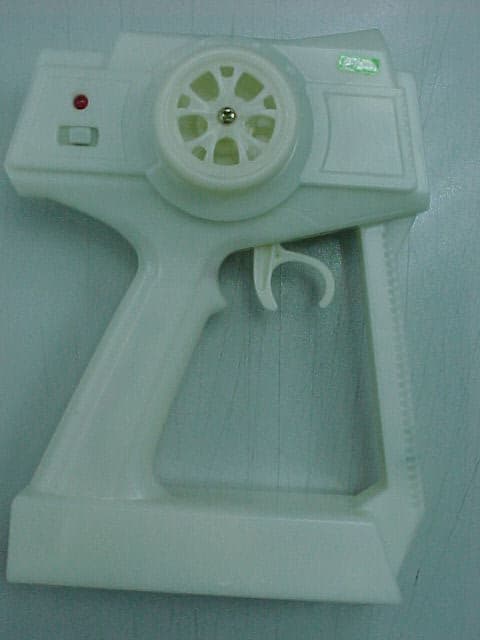
RCB26427
Jul 07, 200526.96-27.28 MHz WIRELESS R/C TOY-TX
Equipment Class
DXX - Part 15 Low Power Communication Device Transmitter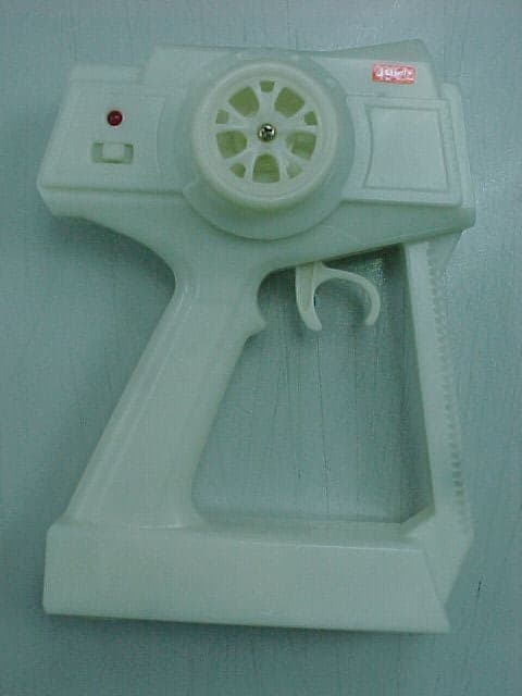
RCB26449
Jul 07, 200549.82-49.90 MHz WIRELESS R/C TOY-TX
Equipment Class
DXX - Part 15 Low Power Communication Device Transmitter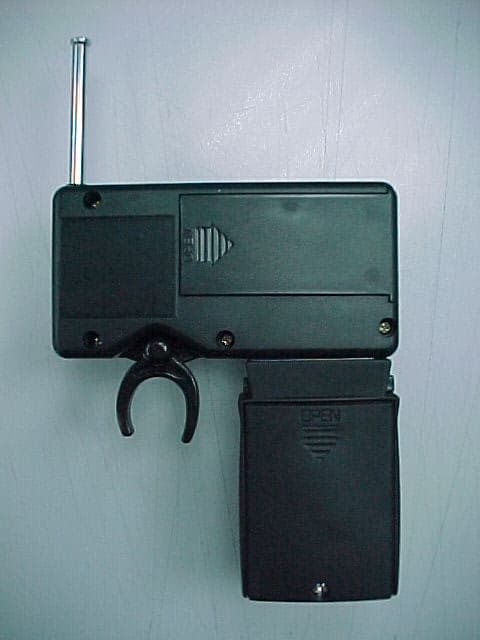
RCB24549
Apr 11, 2005REMOTE CONTROL TRANSMITTER
Equipment Class
DXX - Part 15 Low Power Communication Device Transmitter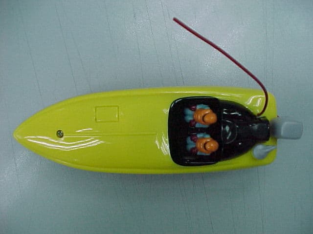
RCB9396A49
Apr 11, 200549MHz REMOTE CONTROL RECEIVER
Equipment Class
CRR - Superregenerative Receiver