RCUIBANEX-807Single Channel RF Amplifier
Inteligain Corporation, Inc.
Click to zoom
Application Details
- Equipment Class
- TNB - Licensed Non-Broadcast Station Transmitter
- Date of Grant
- Apr 28, 2004
- Application Purpose
- Original Equipment
- Date of Application
- Apr 28, 2004
- Equipment Note
- Single Channel RF Amplifier
- Frequency Range
- 851.00000000 - 870.00000000
- Company
- Inteligain Corporation, Inc.
- Country
- United States
Documents & Files
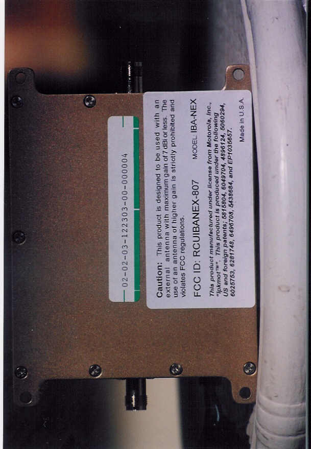
Document Text
Text extracted from the exhibit documents filed with the FCC. Open a document above to read the original.
Users Manual
How many times has this happened to you? You’re trying to call home, or you’re waiting for an important call, but your wireless phone keeps drop- ping calls or displaying No Service ... another frustrating wireless dead zone. You’re not alone. Lack of service, dropped calls and poor connections are the #1 com- plaints from wireless phone users. Your provider’s cover- age never seems to keep you connected in all the areas where you need wireless service. The Solution! Inteligain IBA-NEX amplifier with Inteligain ™ technology, combined with Motorola patented technology, provide optimized communication from your wireless phone provider’s network. Making constant adjustments, the amplifier provides just the right amount of power to both your transmitted and received signals to keep you connected at extended ranges or in challenging geo- graphic conditions. Now there’s a solution that significantly extends your wireless phone’s range, providing up to 20 mile coverage increase, giving you the maximum power allowed for a wireless phone – the Inteligain Amplifier. The Inteligain amplifier provides intelligent system control resulting in optimized power levels communicated from the tower to your wireless phone. Responding to the tower control, the amplifier adds just the right amount of power to your phone, making constant adjustments to keep you connected at all times. The full output delivers up to 20 miles of added signal distance in rural areas, often meaning the difference between making and keeping a connection. The Inteligain’s signal boost means you get greater service coverage, more successful connections, better call quality, and fewer dropped calls. THE IBA-NEX amplifier is the original amplifier that works with any iDEN* Motorola handset and is com- patible with every U.S. iDEN* provider’s system. You never have to change amplifiers when you change phones. Inteligain allows the tower to control your wireless phone’s power levels to optimize system per- formance. The added signal strength provided by the Inteligain amplifier means more reliable tower handoffs, minimizing dropped calls. The high power output broadcasts digital signals over greater distance so that you have more successful data transmissions too. *iDEN is a registered tradmark of Motorola, Inc. **Nextel is a registered trademark of Nextel Communications, Inc. Keeping you and your Data Connected The “Real” Name in Affordable Mobile and Home Based Cellular Amplificaton Solutions IBA-NEX 26500 W. Agoura Road, Suite 102-656 Calabasas, California 91302 tel: 818-874-9990 fax: 818-874-9229 www.inteligain.com FOR USE ON Nextel** SYSTEM Manufactured under license from Motorola, Inc. up to 20 Miles coverage increase Manufactured under license from Motorola, Inc. Specifications TX Uplink/Transmit RX Downlink/Receive Frequency Range 806 - 825 MHz 851 - 870 MHz Output Power 3 Watt @ 813 MHz typical TX Gain 6 dB to 29.3 dB, @ 813 MHz Rx Noise Figure 7 dB max 7 dB max VSWR (typical) 2:1 2:1 Maximum Input Power 60 milliwatts Input DC Power 10V – 24V, 2 Amps maximum Operating Temperature Range -20°C to 70°C Overall Dimensions 5.25” L x 4.5” W x 1.56” H (134mm L x 115mm W x 40 mm H) Net Weight 1.36 kg (3 lbs) RF Connectors TNC Female Included Items One 2M (78”) DC power cord Optional Items Carrying case, Cigarette Lighter Adaptor, Suction Cup Antenna, AC/DC Adaptor, Phone Interconnect Cable ■ Up to 3-watt output delivering maximum signal gain for your wireless phone. ■ Works with any iDEN* handset, on any frequency and on any U.S. providers’ iDEN* system. ■ Unique technology is combined with Motorola patented technology for up to 20 miles of added signal distance. ■ More connections in limited service areas. ■ Better call quality, extended range, and fewer dropped calls. ■ Enhances the transmitting of calls. ■ Significantly improves range and reliability for data transmissions. ■ Approved by FCC laboratory. Keeping you and your data connected Please call for your nearest distributor This product manufactured under license from Motorola, Inc., “lpkmot™”. This product is produced under the following US and foreign patents; 5815804, 6049704, 4896124, 5060294, 6025753, 6281748, 6496708, 5438684, and EP1035657. *iDEN is a registered tradmark of Motorola, Inc.
Users Manual
IBA-NEX RF Amplifier Installation Manual Page 1 of 2 Copyright 2002, Inteligain Corporation. All rights reserved. Rev C D00000413 Manufactured in the U.S.A. under license from Motorola Inc. Note: Before installing the IBA-NEX RF Amplifier, please read the entire contents of this manual. Parts List Item Qty Description 1 1 IANEX Inteligain TM Signal Amplifier 2 1 2 Meter (78”) DC Power Cable Tools and Other Materials Required Item Description 1 Electric drill (as required for signal amplifier mounting holes) 2 Screw driver 3 Qty 4 screws (length and type as required for signal amplifier mounting) 4 Wire cutters / strippers 5 Qty 2 wire connection insulators or insulating material (as required for DC power cable connection to 12V DC system) WARNINGS! ∇ Directly wired vehicle antennas must be mounted a minimum distance of 20 cm away from all persons and must not be co-located or operating in conjunction with any other antenna. ∇ Mounting a signal amplifier in the engine cavity or on the underside of the vehicle will void the manufacturer’s warranty. ∇ Subjecting the amplifier to voltages greater than 30 Volts DC will damage the amplifier and void the manufacturers warranty. ∇ Any vehicle with an electrical system of greater than 30 Volts DC should use a step-down voltage regulator to bring the voltage within the DC operating power range of the amplifier (10 to 30V dc). ∇ Under no circumstances should the amplifier be powered up without a properly connected 50 ohm 800 MHz cellular antenna or the amplifier may be damaged, resulting in the manufacturer’ warranty being void. ∇ For optimum performance and compatibility with the service provider requirements, it is recommended that an external antenna with a maximum gain of 3dB be installed, a minimum distance of 20 cm from all persons. ∇ Use of this amplifier with an antenna of gain higher than 7 dBi is in violation of FCC regulations for which the offender will be fully liable, and warranty claims will be voided. It is recommended that only certified automotive installation technicians install this product in a vehicle. Installation by any other person is at the risk of the vehicle owner and operator. Installation Selecting a Suitable Location To Mount The Signal Amplifier Locate a suitable place to mount and conceal the signal amplifier. Suggested mounting locations include: under the dashboard, under the seat, or in the trunk. For peak performance the signal amplifier should be mounted as close to the phone handset as possible. The amplifier’s location should be easily accessible and mounted away from moving parts, as well as excessive heat and moisture. IBA-NEX RF Amplifier Installation Manual Page 2 of 2 Copyright 2002, Inteligain Corporation. All rights reserved. Rev C D00000413 Manufactured in the U.S.A. under license from Motorola Inc. Installation Cautions ∇ Use caution to avoid drilling through or near fuel lines or fuel tanks; brake lines; or electrical wiring. ∇ Do not mount the signal amplifier or its associated wiring in a location that may interfere with the safe operation of the vehicle. ∇ If the fuse is changed from the 3 amps to a higher rating the warranty is void. Purchaser of the amplifier would be responsible for the repair of the unit. ∇ Caution: Connection to the negative side with the positive lead will cause damage to the amplifier. Installation Of The Signal Amplifier Signal Amplifier 1.5 M Cable Color/ Black Black (12 V DC) Antenna * 1 Antenna Cable * 1 * 1 Optional items must be purchased separately . Phone/Cradle or RF output device * 1 1 2 3 Signal Amplifier 1.5 M Cable Color/ Black Black (12 V DC) Antenna * 1 Antenna Cable * 1 * 1 Optional items must be purchased separately . Phone/Cradle or RF output device * 1 1 2 3 Typical Installation For Under The Seat Mounting 1. For safety, disconnect the vehicle’s negative “−“ battery terminal to remove power from the vehicle. 2. Drill holes and mount the signal amplifier (ITEM 1) in the selected location. 3. Connect the coloured striped black wire of the supplied 2 Meter (78”) power cable (ITEM 3) for the signal amplifier to a positive connection on the vehicle’s electrical system. Choose a 10 to 30 Volt DC circuit that is: fuse protected; and ignition switched. (Often referred to as the “Accessory output”) 4. Attach the solid black wire of the supplied 2 Meter (78”) power cable (ITEM 3) to a vehicle electrical ground point. 5. Attach one end of the antenna cable* 1 to the 3dB antenna. The other end is connected to the cellular phone handset via a cradle or an RF output cable *1 to the signal amplifier’s ANTENNA output connector 6. Connect the amplifier’s PHONE input connector to the cellular phone handset via a cradle or an RF output cable. 7. Reconnect the vehicle’s negative “−“ Battery terminal. Limited Warranty Inteligain Corporation warrants that this product is free from any defects in material or workmanship for a period of one year. If a defect in material or workmanship is found, Inteligain Corporation agrees to repair or replace the product at its own discretion, free of charge to the original purchaser. Please return the product along with proof of purchase to the original authorized dealer. This warranty is null and void if the product has been modified, abused, tampered with, subjected to abnormal conditions, if the fuse is changed to a higher rating than 3 amp, or transferred to someone other than the original purchaser. All brands and trademarks are the property of their respective owners. Use a 3dB antenna for Optimal Performance
Cover Letter(s)
LEON PAUL KASS, LLC CONSULTANT IN WIRELESS COMMUNICATION 9695 135 th Street Seminole, Florida 33776-1434 Phone 727-593-3100 Fax 727-593-7950 E Mail lpk @ fdn.com Confidentiality Request For The Inteligain IBA-NEX RF Amplifier The IBA-NEX is a full duplex RF amplifier for use on the Nextel system with iDEN branded phones from Motorola, Inc., that operates in the 806-825 MHz frequency range for phone transmission and the 851-870 MHZ frequency for the phone receive range. The unit incorporates technology under license from Motorola Inc., via the use of sections of patents # US5815804, US6049704, US4896124, US5060294, US6025753, US6281748, EP1035657, US6496708, and US543684, and other proprietary circuit designs. We request that the schematic drawing, and the block diagram of operation remain Confidential.
Cover Letter(s)
26500 W. Agoura Road, Suite 102-656 Calabasas, CA 91302 Telephone: 818-874-9990 Fax: 818-874-9229 6/5/03 AGENT AUTHORIZATION To whom it may concern, In regards to the F.C.C. application for equipment authorization, Inteligain Corporation has appointed Leon Paul Kass, of Leon Kass LLC., Consultant to act as our agent pursuant to the following sections of the F.C.C. document listed below. Mr. Kass has full authority to respond to all necessary answers to complete this transaction for our model SG 8-19 amplifier. SECTION5301 (ANTI-DRUG ABUSE) CERTIFICATION: The applicant hereby certifies that neither the applicant nor any party to the application is subject to a denial of Federal benefits, that include FCC benefits, pursuant to Section 5301 of the Anti-Drug Abuse Act of 1988, 21 U.S.C. §862 because of a conviction for possession or distribution of a controlled substance. See 47 CFR 1.2002(b) for the definition of a “party” for these purposes. APPLICANT/AGENT CERTIFICATION: I certify that I have authorized Leon Paul Kass to sign this application. All of the statements herein and the exhibits attached hereto are true and correct to the best of my knowledge and belief. In accepting a Grant of Equipment Authorization issued by the FCC as a result of the representations made in this application, the applicant is responsible for (1) labeling the equipment with the exact FCC ID specified in this application, (2) compliance statement labeling pursuant to the applicable rules, and (3) compliance of the equipment with the applicable technical rules. If the applicant is not the actual manufacturer of the equipment, appropriate arrangements have been made with the manufacturer to ensure that production units of this equipment will continue to comply with the FCC’s technical requirements. Authorizing an agent to sign this application is done solely at the applicant’s discretion; however, the applicant remains responsible for all statements in this application. Thank You Dana Mitchell President
Cover Letter(s)
American Telecommunications Certification Body Inc. 6731 Whittier Ave, McLean, VA 22101 February 5, 2004 RE: FCC ID: RCUIBANEX-807_ATCB001087 Attention: Leon Paul Kass I have a few comments on this Application. 1. Please note that the 731 states part 24 as one of the licensed rule parts under which this device is to operate. Please note that the frequency bands listed and tested do not fit into either the narrow band or the wide band PCS frequencies. Please remove part 24 from this application. Alternately, please explain how this amplifier fits into Part 24. 2. Please indicate the appropriate equipment code for the device on the 731 form (item 4a on the 731). Amplifiers would be AMP. 3. Please note that except in extenuating circumstances internal photos are not allowed to be held confidential. Please remove the internal photos from the confidentiality request. 4. Please note that the request for confidentiality is not the proper place for the technical specifications of a device. Please remove the technical specs shown on the request for confidentiality and restrict the request for confidentiality to listing those items that are to be confidential. 5. Please note that a report must provide evidence of compliance to ALL rule parts to which certification is requested. Your report only addresses part 90 and only 806 to 830MHz. Please provide evidence of compliance to all rule parts and all frequency ranges for which certification is requested. Please remember that a report must address all aspects of the rule parts that are applicable. Alternately, please remove rule parts, frequency ranges that have not been shown compliant from the application. 6. Please note that the report classifies this as an amplifier for F3E modulation. Please also note that TDMA/GSM modulation types were used. GSM is a digital wideband modulation which may exceed the modulation limitations in some of the rule parts for which certification is requested.. Please note that the device must show compliance all modulation types for all of the rule parts for which certification is requested. While it may be assumed that compliance with TDMA and GSM modulations would also show compliance with narrower emissions, the FCC has stated that all modulation types are to be tested. Please correct the report as necessary, testing the device using all appropriate modulation types. 7. Please note that amplifiers must faithfully reproduce the input signal. This can only be determined by comparison of input and out put signals. Please provide both input and output wave forms. Input wave forms should be set to the maximum input level for the amplifier. 8. Please provide the factory tune up procedure for this device. As this is an amplifier, and there are no frequency determining components, this may be a simple statement to the affect that there is no tuning procedure. However, if there are adjustments for ‘fine tuning’ band pass filters, this would need to be explained. 9. Please provide intermodulation test data. This may be done using two or three CW input signals. 10. Please note that actual ERP/EIRP measurements must be made. Please note that it is unclear from your report if you used the antenna substitution method specified in TIA 603. Your reference to 2.2.1.1 is for conducted carrier output power, not radiated spurious emissions as stated in the report. The limits listed in the report are also 54. However, you have not specified 54 what? It is assumed this is 54dBuV. This, however, would not be correct as the limit for ERP/EIRP measurements of spurious emissions of licensed devices is -13dBm (94dBuv). The report data indicates that only field strength emissions levels were measured. Please explain, and or retest using the proper antenna substitution method specified in 2.2.12 of the latest edition of TIA 603. 11. Please provide an MPE report showing compliance to the rf exposure rules. 12. Please note that the report on page 31 states that this device is used in the part 22E paging bands. Please note that while the frequency bands requested may lie in the 22F and 22G rule parts, this z Page 2 February 5, 2004 device frequency range is not in the allocated part 22E frequency bands. Please explain and/or please test to the correct frequency bands for device operation as stated in the application. 13. Please note that your report references 90.219g. Please note that there is no such section in 90.219. Please use current CFR rule parts when referencing CFR 47. Please provide a report specifically referencing all appropriate rules parts for which this application applies. 14. Please note that while the measured conducted power is the power that will be listed on the grant, 90.219 restrict amplifiers and signal boosters to a maximum ERP. Please note that while you have provided conducted antenna terminal measurements, you have not provided ERP measurement data showing compliance to the ERP limit. Please show evidence of compliance to the ERP limit for this device. Please note that this ERP measurement is to be done using the same gain antenna for which MPE compliance is reported (see item 11). 15. Please note that the theory of operation states that this device operates in the 824-849 MHz, 1850- 1920 MHz, 869-894 MHZ and 1930-1990 MHz range. Please note that the test report states the device operates only in the 806 - 830MHz range. Please also note that the 731 and advertising literature states the device operates in the 806 - 825 MHz and the 851 - 870 MHz range, while the theory of operation states the device operates in the 806-821 MHz and the 851-866 MHz range. Please provide documentation and test reports that are consistent and that report the actual frequency range for which certification is being requested. Please correct all documentation to state the same frequency ranges. Dennis Ward mailto:[email protected] The items indicated above must be submitted before processing can continue on the above referenced application.…
Text truncated - open the document above for the full version.
Cover Letter(s)
Hi Leon A couple issues with the report. Page 6 of the report states that Parts 22 and 24 were tested for this device. This is incorrect and will have to be changed to reflect the device and what was actually tested. The report states DXW yet also states TDMA and GSM. TDMA is DXW but, while GSM is a variant of TDMA, the designator for GSM is GXW – Was GXW also meant to be on the 731 - please explain. (see item 6 of the ATCB comments) The 731 says that F2E is a modulation type, yet the new report has no such modulation test data – each type modulation must have supporting test data. (see item 6 of the ATCB comments) The 731 states the power is 100mw for the 851 to 870MHz range, yet the conducted power on page 15 of the report only shows a max of 18.6mw – please explain and /or correct. The 731 states the power is 500mw for the 806 to 821MHz range, yet the conducted power on page 15 of the report only show a max of 214mw - please explain and /or correct. The report does not address item 14 (90.219 ERP limitations on the fundamental). Please measure the erp of the device in accordance with 90.219b using the maximum antenna gain. Please show how this device meets 90.219a. (see item 5 of the ATCB comments – a filing must address all aspects of the rule parts that are applicable) Thanks Dennis
Parts List/Tune Up Info
LEON PAUL KASS, LLC CONSULTANT IN WIRELESS COMMUNICATION 9695 135 th Street Seminole, Florida 33776-1434 Phone 727-593-3100 Fax 727-593-7950 E Mail lpk @ fdn.com Tune Up Procedure For The Inteligain IBA-NEX RF Amplifier The IBA-NEX is a full duplex RF amplifier for use on the Nextel system with iDEN branded phones from Motorola, Inc., that operates in the 806-825 MHz frequency range for phone transmission and the 851-870 MHZ frequency for the phone receive range. The unit incorporates technology under license from Motorola Inc., via the use of sections of patents # US5815804, US6049704, US4896124, US5060294, US6025753, US6281748, EP1035657, US6496708, and US543684, and other proprietary circuit designs. There is no frequency determining components, so there is no tune up procedure.
RF Exposure Info
F F C C C C I I D D : : R R C C U U I I B B A A N N E E X X 8 8 0 0 7 7 R R E E P P O O R R T T # # : : R R V V 4 4 8 8 0 0 6 6 9 9 - - 0 0 0 0 3 3 8 8 A A p p r r i i l l 2 2 0 0 0 0 4 4 71 3.8.1 RF Exposure – MPE Calculations Input Transmitter Power: 250 mW Antenna Gain: 3 dB Cable loss: 2 dB @ 806– 825 MHz 2 dB @ 851 – 870 MHz Frequency range: 806-825 MHz and MHz Assumptions 1. A single ¼ wavelength radiating antenna is assumed. 2. Closest exposure distance is assumed to be 20 cm F F C C C C I I D D : : R R C C U U I I B B A A N N E E X X 8 8 0 0 7 7 R R E E P P O O R R T T # # : : R R V V 4 4 8 8 0 0 6 6 9 9 - - 0 0 0 0 3 3 8 8 A A p p r r i i l l 2 2 0 0 0 0 4 4 72 RF Exposure – MPE Calculations Calculations The following results shall be assumed to be accurate for the far-field only. These predictions will over-estimate power density in the near–field. Based on the use of a ¼ wavelength radiator, a distance of 20 cm is considered to be in the far-field for all cases. S = PG/4*PI*R 2 @ 806-825 MHz P is 250mW G is 2 dB (Antenna gain – loss) or 10 (2/20) or 1.25 R is 20 cm S = 0.056 mW/cm 2 For Occupational/Controlled Exposure From 300 to 1500 MHz, power density limit is f/300 mW/cm 2 @ 806MHz, power density limit is 2.69 mW/cm 2 For General Population/Uncontrolled Exposure From 300 to 1500 MHz, power density limit is f/1500 mW/cm 2 @ 806MHz, Power density limit is 0.54 mW/cm 2 Conclusion: Meets MPE limits
Test Report
APPLICATION FOR CERTIFICATION FOR A Nextel Amplifier M/N: IBA-NEX PER FCC 47: Part 2, 90 Inteligain Corporation Inc 26500 Agoura Road Calabasas, CA 91302 FCC ID: RCUIBANEX807 REPORT #: RV48069-003 Prepared By DNB Engineering, Inc. 5969 Robinson Ave Riverside CA, 92503 On 8 April 2004 F F C C C C I I D D : : R R C C U U I I B B A A N N E E X X 8 8 0 0 7 7 R R E E P P O O R R T T # # : : R R V V 4 4 8 8 0 0 6 6 9 9 - - 0 0 0 0 3 3 8 8 A A p p r r i i l l 2 2 0 0 0 0 4 4 2 TEST LAB PERSONNEL Test Performed by: Date Signature Thomas Elders 8 April 2004 APPROVALS Management Approval Date Title Signature Les Payne 8 April 2004 Sr. Engineering Manager F F C C C C I I D D : : R R C C U U I I B B A A N N E E X X 8 8 0 0 7 7 R R E E P P O O R R T T # # : : R R V V 4 4 8 8 0 0 6 6 9 9 - - 0 0 0 0 3 3 8 8 A A p p r r i i l l 2 2 0 0 0 0 4 4 3 TABLE OF CONTENTS Section # Page # TABLE OF CONTENTS...............................................................................................................................3 TABLE OF FIGURES....................................................................................................................................5 1 ADMINISTRTIVE DATA.....................................................................................................................6 1.1 CERTIFICATIONS AND QUALIFICATIONS.............................................................................................6 1.2 MEASUREMENT REPUTABILITY INFORMATION..................................................................................6 1.3 TEST METHODOLOGY........................................................................................................................7 3.4.............................................................................................................................................................7 1.4 TEST EQUIPMENT USED.....................................................................................................................7 1.5 DEVIATIONS.......................................................................................................................................8 1.6 TEST DESCRIPTION 2.1033 (B) (6).....................................................................................................8 1.6.1 RF Power Output......................................................................................................................8 1.6.2 Modulation Characteristics......................................................................................................8 1.6.3 Occupied Bandwidth.................................................................................................................8 1.6.4 Spurious Emissions at Antenna Terminals...............................................................................8 1.6.5 Field Strength of Spurious radiation........................................................................................9 1.6.6 Frequency Stability...................................................................................................................9 2 APPLICATION FOP CERTIFICATION..........................................................................................10 2.1033 (b) 1 Name of Applicant: Inteligain Corporation Inc.........................................................10 2.1033 (b) 2 FCC ID No: RCUIBANEX807................................................................................10 2.1033 (b) 4 FCC Emissions Designator: GXW, DXW..................................................................10 2.1033 (b) 5 Frequency Range: Uplink 806-825; Downlink 851-870............................................10 2.1033 (b) 6 Rated Output Power: Uplink: +24dBm, Downlink –2dBm.......................................10 2.1033 (b) 7 Maximum Power Rating: +24dBm.............................................................................10 2.1033 (b) 8 Input Power: 0 dBm.................................................................................................10 2.1033 (b) 9 Tune-Up Procedure........................................................................................................11 2.1033 (b) 10 Schematic Diagram......................................................................................................11 2.1033 (b) 11 Equipment Identification Plate or Equivalent..............................................................11 2.1033 (b) 12 Photographs of Unit Internal & External.....................................................................11 2.1033 (b) 13 Description of Modulation System..............................................................................11 3 2.1033 (B) 14: TEST DATA.................................................................................................................12 3.1 TEST RESULT SUMMERY..................................................................................................................12 3.1.2 Frequency Spectrum Investigated..................................................................................................12 3.2 TEST SETUP PHOTO..........................................................................................................................13 3.3 TEST BLOCK DIAGRAM....................................................................................................................14 3.4 RF POWER OUTPUT.........................................................................................................................15 3.5 MODULATION CHARACTERISTICS....................................................................................................22 3.6 OCCUPIED BANDWIDTH...................................................................................................................23 3.7 SPURIOUS EMISSIONS AT ANTENNA TERMINALS.............................................................................60 3.8 FIELD STRENGTH OF SPURIOUS RADIATION....…
Text truncated - open the document above for the full version.
Contact Information
Applicant
Leon Paul Kass(Engineering Manager)
Technical Contact
Leon Paul Kass, LLCLeon P Kass
[email protected]727-593-3100
9695 135th Street · Seminole, Florida · United States
Technical Specifications
| # | Rule Parts | Frequency Range | Power Output | Emission | Tolerance |
|---|---|---|---|---|---|
| 4 | 9 | 851 MHz - 870 MHz | 19.00 mW | DXW | Amp |