RDKRP800RTTransmitter, RP-800-RT
e-Business International Inc.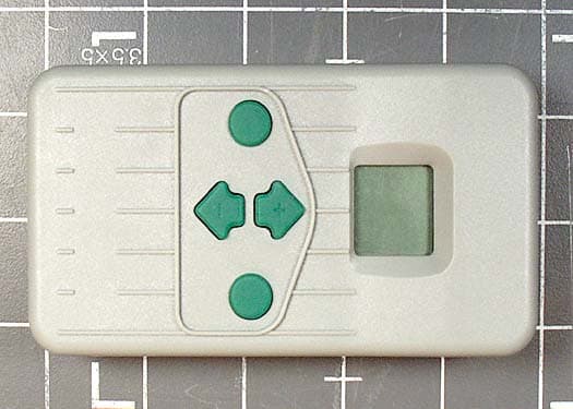
Click to zoom
Application Details
- Equipment Class
- DSC - Part 15 Security/Remote Control Transmitter
- Date of Grant
- Aug 24, 2003
- Application Purpose
- Original Equipment
- Date of Application
- Aug 24, 2003
- Equipment Note
- Transmitter, RP-800-RT
- Frequency Range
- 315.00000000 - 315.00000000
- Country
- United States
Documents & Files
Document Text
Text extracted from the exhibit documents filed with the FCC. Open a document above to read the original.
Users Manual
Specifications.......................................... Operating Specifications . Address range: 0-127 . Maximum stations supported: 48 . Run Time: 8 settings from 1 to 30 minutes . Range: up to 450 feet Electrical Specifications . Power Source Transmitter: 9V Alkaline Battery . Power source Receiver: 24VAC, 0.010Amps (from SRC) . Transmitter type: SAW Stabillized . Receiver type: Superheterodyne . System Operating frequency: 315MHZ Default Settings . Address=0 (may be varied from 0-127) . Number of stations= 9 (may be varied from 1-48) . Run Time: 10 minutes Dimensions Transmitter: Receiver: . Height: 4 3/4” . Height: 4 3/4” . Wideth: 2 1/2” . Wideth: 2 1/2” . Depth: 1 1/4” . Depth: 1” CHANGING THE RUN TIME..................................................... 1. If the unit is OFF(no display), power the transmitter up by pressing any of the buttons for at least 3 second then releasing the button. The transmitter will first illuminate the entire display for 3 second then display the active station. 2. Simultaneously press the ↑ and ↓ buttons, until the word “ RUN TIME” along with the current Run Time is displayed(default is 10 minutes). The display will be blinking at this point. If more than 5 seconds go by without a button being pressed, the Transmitter will revert back to displaying the active station. 3. Use the ↑ and ↓ buttons to change the Run Time to any of 8 settings ranging from 1 to 30 minutes. Then do not touch any of the buttons for 5 seconds and the display will stop blinking, and return back to the active station. CHANGING THE TRANSMITTER ADDRESS................................................... 1. If the unit is OFF (no display), power the Transmitter up by pressing any of the buttons for at least 3 seconds then releasing the button. The Transmitter will illuminate the entire displaly for 1 second then display the active station. 2. Simultaneously press the ↑ and ↓ buttons, until the word “ RUN TIME” along with the current Run Time is displayed. The display will be blinking at this point. 3. While the display is blinking and showing the current Run Time, Press the “ON” button. The word “ADDRESS” will now illuminate and the current address will be blinking. Note that if more than 5 seconds go by without a button being pressed, the Transmitter will revert back to displaying the active station. 4. Use the ↑and ↓ buttons to change the address to any value between 0 and 127. Then do not touch any of the buttons for 5 seconds and the display will stop blinking, and return back to the active station. CHANGING THE MAXIMUM STATION NUMBER.................................... ...... 1. If the unit is OFF (no display), power the Transmitter up by pressing any of the buttons for at least 3 seconds then releasing the button. The Transmitter will first illuminate the entire display for 1 second then display the active station. 2. Simultaneously press the ↑ and ↓ buttons, until the word “ RUN TIME” along with the current Run Time is displayed. The display will be blinking at this point. 3. While the display is blinking and showing the current address, press the “ON” button. The display will continue to blink, but the word “ ADDRESS” will be illuminated. 4. Press the “ON” button again. The display will continue to blink, but the word “ADDRESS” will no longer be illuminated. 5. Use the ↑and ↓ keys to change the maximunm station number to the value you desire. Then, do not press any button for 5 seconds and the display will stop blinking and return to the active station number. 6. You may now change the active setting up to the new maximum station value. CHANGING THE RECEIVER ADDRESS.................................................... 1. Hold down the single button on the face of your Receiver while you are plugging it into an active wiring harness(one connected to a powered controller). When this is done, the Receiver will keep 4 items. 2. After the Receiver starts to beep, release the button. 3. Press either the “ON” or “OFF” button of your Transmitter. 4. The Receiver well beep 4 additional times indicating that it has learned the new Transmitter address and will respond only to it from this point on. ACTIVATING A STATION WITH THE RAIN PRO REMOTE CONTROL SYSTEM............. The Rain Pro system will allow you to remotely turn on and off any station on your RPC(or future Rain Pro controller) with the press of a button. Once on, the station will run for the run time ou have designaed in the remote. To remotely activate a station or program follow the steps below: 1. Plug the Receiver into an active wiring harness(one attached to a powered controller)and wait for 2 beeps indicating theat the Receiver is ready. 2. If your Transmitter is not on( no display), press any utton for at leas 3 seconds and release. The transmitter will first illuminate the entire display for 3 second then display the active station. 3. Use the ↑ and ↓ buttons to display the station or program you would like to start. 4. Momentarily press the “ON” button to start the station or program. The Transmiter will display the word “ TRANSMIT” and will flash for about 4 seconds indicating that it is sending the command to the Receiver. If you are near the Reciever, you will hear it beep 2 times, indicating that it has received the command. 5. Press the “OFF” button to turn off any station that is on. The display will again read “TRANSMIT” and flash, and the Receiver will again beep twice. The RPCM system is designed to turn one station on at a time. Therefore, truning a sation on while another station is already on will cause the first station to turn off. MAXIMIZING OPERATING RANGE............................................................... There are many factors which influence operating range (see “A Word About Range”). Listed below are a few things you can do to assure you are getting the maximum range possible. 1. Do not install the outlet of the wiring harness (that the Receiver connects to ) near large sources of me…
Text truncated - open the document above for the full version.
Users Manual
TABLE OF CONTENTS INTRODUCTION AND INSTALLATION 1. Introduction 2. RP-800-RC Components 3. Components, continued 4. Wiring Harness Connection Kit 5. Maximizing Operating Range PREPARING TRANSMITTER A ND RECEIVER FOR USE 6. Preparing the Transmitter For Use 7. Installing the Transmitter Battery 8. Changing the Remote Activated Station Run Time 9. Notes 10. Changing the Maximum Station Number 11. Preparing the Receiver For Use 12. Changing the Receiver Address TRANSMITTER AND RE CEIVER OPERATION 13. Activating a Station with The RP-800-RC Remote Control System 14. Changing the Transmitter Address TROUBLESHOOTING AND SPECIFICATIONS 15. Troubleshooting Guide 16. Specifications 17. FCC Compliance Notice 18. Information Data FCC COMPLIANCE This device complies with Part 15 of the FCC Rules. Operation is subject to the following two conditions: (1) this device may not cause harmful interference, and (2) this device must accept any interference received, including interference that may cause undesired operation. This equipment has been tested and found to comply with the limits for a Class B digital device, pursuant to Part 15 of the FCC Rules. These limits are designed to provide reasonable protection against harmful interference in a residential installation. This equipment ge nerates, uses, and can radiate radio frequency energy and, if not installed and used in accordance with the instructions, may cause harmful interference to radio communications. However, there is no guarantee that interference will not occur in a particular installation. If this equipment does cause harmful interference to radio or television reception, which can be determined by turning the equipment off and on, the user is encouraged to try to correct the interference by one or more of the following measures: -- Reorient or relocate the receiving antenna. -- Increase the separation between the equipment and receiver. -- Connect the equipment into an outlet on a circuit different from that to which the receiver is connected. -- Consult the dealer or an expe rienced radio/TV technician for help. Notice: changes or modification s not expressly approved by the party responsible for compliance c ould void the user's authority to operate the equipment. 17 RP-800-RC COMPONENTS Transmitter Receiver Wiring Harness 2 TROUBLESHOOTING GUIDE 15 WIRING HARNESS CONNECTION KIT WIRE CONNECTIONS: The wiring harness is included with t he purchase of the Remote control 4 ACTIVATING A STATION WITH THE REMOTE CONTROL SYSTEM The RP-800-RC System will allow you to remotely turn on and off any station on your SRC, ICC, or future Rain Pro controller with the press of a button. Once on, the station will run for the run time you have designated in the remote. To remotely activate a station or program follow the steps below: 1. Plug the Receiver into a wiring harness that is connected to a powered controller and wait for two beeps indicating that the Receiver is ready. 2. If your Transmitter is not on (no display), press any button for at least one second and release. The Transmitter will first illuminate the entire display, then display the active station. 3. Use the ↑ and ↓ buttons to display the station or program you would like to start. 4. Press the “ON” button to start the station or program. The Transmitter will display the word “TRANSMIT” and the letters “ON”. Both will flash for about 4 seconds indicating that it is sending the command to the receiver. If you are near the Receiver, you will hear it beep 2 times. This indicates that the Receiver has received the command. 5. Press the “OFF” button to turn off any station that is on. The display will read “TRANSMIT” and the letters “OFF”. Both will flash for about 4 seconds, and the Receiver will beep again twice. The RP-800-RC System is designed to turn on one station at a time (unless you activate a program). Therefore, turning a station on while another station is operating will cause the operating station to turn off. NOTE: The RP-800-RC remote can activate any station on the controller whether the controller dial is in the “SYSTEM OFF”, “RUN” or “RUN/BYPASS SENSOR” modes. If a sensor device has been wired to the controller, the RP-800-RC remote will NOT override the sensor for manual operation. 13 PREPARING THE TRANSMITTER FOR USE Your RP-800-RC System is designed to work right out of the box. This means that other than installing the battery, you may choose to skip this entire section. However, we recommend you read it because with a few simple steps you can customize your RP-800-RC toad functionality and security to your system. Beware that if you change your transmitter a ddress or maximum station number as described on the following pages, you should make a note of the settings, since when the battery is removed and a new one is installed, the transmitter will revert back to the original settings. 6 PREPARING THE RECEIVER FOR USE As stated earlier, your RP-800-RC System is designed to work right out of the box. If you have decided to change your Transmitter address as described in the previous section, you must allow the Receiver to “lea rn” this new address. Once learned, the only way to remove the address from the Receiver memory is to learn a different address. This can be done by following the simple steps outlined below. NOTE: The RP-800-RC remote receiver should not be permanently installed in an outdoor or unsheltered location. 11 CHANGING THE REMOTE ACTIVATED STATION RUN TIME You have the ability to adjust the amount of time that a station will run once it has been turned on by your RP-800-RC System. This does not affect the run time programmed into your controller. This adju stment is made using the transmitter as described below. To change the Remote Activated Station Run Time follow the steps below: 1. If the unit is off (no display), power the transmitter up by pressing on any of the buttons for at least 1 second and then releasing the button. The transmitter will first …
Text truncated - open the document above for the full version.
Block Diagram
RP-800-RR 600kHz 4kHz 4.914MHz RP-800-RT 4kHz DATA MCU 16C54 OSCO 4.0MHz OSC1 MCU 16C57 315MHz OSCO OSC1 4.0MHz 315MHz
Cover Letter(s)
Confidentality Request for RP-800 RT and RP-800 RR e-BI wishes to maintain the confidentiality of the schematic design and the functional description for the transmitter RP-800 RT and the receiver RP-800 RR. Our FRN is 0008873515 FCC Grantee code is RDK Sincerely yours, Jason Mershon VP Engineering
External Photos
Top Bottom Left Right
ID Label/Location Info
Location of Label on RP-800 RT RP-800 RT Label Goes here in this area.
ID Label/Location Info
1 RAIN PRO Model : RP-800 RT FCC ID: RDKRP800RT CANADA: ISC: This device complies with FCC Rules Part 15. Operation is subject to the following two conditions: (1) This device may not cause harmful interfer- ence and (2) this device must accept any interference that may be received including interference that may cause undesired operation. Made in China
Internal Photos
Interior with Cover Removed PCB Top PCB Bottom
Test Report
Page 1 of 43 Report No.: FC03-025A ADDENDUM TO FC03-025 TEST REPORT FOR THE TRANSMITTER (RP-800-RT) & RECEIVER (RP-800-RR) FCC PART 15 SUBPART B SECTIONS 15.107 & 15.109 CLASS B AND FCC PART 15 SUBPART C SECTION 15.231 COMPLIANCE DATE OF ISSUE: AUGUST 8, 2003 PREPARED FOR: e-BI 10700 SW Beaverton Hillsdale Hwy, Ste. 655 Beaverton, OR 97005 PREPARED BY: Joyce Walker CKC Laboratories, Inc. 5473A Clouds Rest Mariposa, CA 95338 P.O. No.: 7005 W.O. No.: 79450 Date of test: March 21 - April 9, 2003 Report No.: FC03-025A This report contains a total of 43 pages and may be reproduced in full only. Partial reproduction may only be done with the written consent of CKC Laboratories, Inc. The results in this report apply only to the items tested, as identified herein. Page 2 of 43 Report No.: FC03-025A TABLE OF CONTENTS Administrative Information .............................................................................................4 Summary of Results .........................................................................................................5 Conditions for Compliance ..............................................................................................5 Approvals .........................................................................................................................5 FCC 15.31(e) Voltage Variation......................................................................................6 FCC 15.31(m) Number of Channels ................................................................................6 FCC 15.33(a) Frequency Ranges Tested .........................................................................6 FCC 15.35 Analyzer Bandwidth Settings ........................................................................6 FCC 15.203 Antenna Requirements ................................................................................6 FCC 15.205 Restricted Bands..........................................................................................6 EUT Operating Frequency ...............................................................................................6 Temperature And Humidity During Testing....................................................................6 Equipment Under Test (EUT) Description ......................................................................7 Equipment Under Test .....................................................................................................7 Peripheral Devices ...........................................................................................................7 Report of Measurements ..................................................................................................8 Table 1: FCC 15.107 Six Highest Conducted Emission Levels ..........................8 Table 2: FCC 15.109 Six Highest Radiated Emission Levels .............................9 FCC 15.231(a) - 4 Sec Plot ..................................................................................10 FCC 15.231(b)(2) – 20ms Plot.............................................................................11 FCC 15.231(b)(2) – 100ms Plot...........................................................................12 FCC 15.231(b)(2) – 500ms Plot...........................................................................13 Table 3: FCC 15.231(b) Peak Output Levels.......................................................14 Table 4: FCC 15.231(b) Six Highest Radiated Emission Levels: 9kHz-1GHz ...15 Table 5: FCC 15.231(b) Six Highest Radiated Emission Levels: 1-3.5GHz.......16 FCC 15.231(c) – 20dB Bandwidth ......................................................................17 Measurement Uncertainty ................................................................................................18 EUT Setup........................................................................................................................18 Correction Factors............................................................................................................18 Table A: Sample Calculations .............................................................................18 Test Instrumentation and Analyzer Settings ....................................................................19 Spectrum Analyzer Detector Functions ...............................................................19 Peak..........................................................................................................19 Quasi-Peak ...............................................................................................19 Average ....................................................................................................19 EUT Testing.....................................................................................................................20 Mains Conducted Emissions................................................................................20 Radiated Emissions ..............................................................................................20 Appendix A: Information about the Equipment Under Test ...........................................21 I/O Ports ...............................................................................................................22 Crystal Oscillators................................................................................................22 Page 3 of 43 Report No.: FC03-025A Printed Circuit Boards..........................................................................................22 Test Setup Photograph Showing Mains Conducted Emissions ...........................23 Test Setup Photograph Showing Mains Conducted Emissions ...........................24 Test Setup Photograph Showing Radiated Emissions .........................................25 Test Setup Photograph Showing Radiated Emissions .........................................26 Test Setup Photograph Showing Radiated Emissions .......…
Text truncated - open the document above for the full version.
Test Setup Photos
TEST SETUP PHOTOGRAPH SHOWING MAINS CONDUCTED EMISSIONS Test Setup Mains Conducted Emissions - Front View TEST SETUP PHOTOGRAPH SHOWING MAINS CONDUCTED EMISSIONS Test Setup Mains Conducted Emissions - Side View TEST SETUP PHOTOGRAPH SHOWING RADIATED EMISSIONS Test Setup Radiated Emissions - Front View TEST SETUP PHOTOGRAPH SHOWING RADIATED EMISSIONS Test Setup Radiated Emissions - Back View TEST SETUP PHOTOGRAPH SHOWING RADIATED EMISSIONS Test Setup Radiated Emissions - X Axis TEST SETUP PHOTOGRAPH SHOWING RADIATED EMISSIONS Test Setup Radiated Emissions - Y Axis TEST SETUP PHOTOGRAPH SHOWING RADIATED EMISSIONS Test Setup Radiated Emissions - Z Axis
Contact Information
Applicant
jason mershon(vp engineering)
Technical Contact
CKC Laboratories, Inc.Mary Ellen Clayton
[email protected]209-966-5240
5473-A Clouds Rest · Mariposa, California · United States
Non-Technical Contact
CKC Laboratories, Inc.Mary Ellen Clayton
[email protected]209-966-5240
Test Firm
CKC Laboratories, Inc.Steve Behm
Technical Specifications
| # | Rule Parts | Frequency Range | Power Output |
|---|---|---|---|
| 1 | 15.231 | 315 MHz - 315 MHz | - |