REDHP2291-001T2.4GHz Wireless Digital Transmitter
Classic Tech Development Ltd
Click to zoom
Application Details
- Equipment Class
- DTS - Digital Transmission System
- Date of Grant
- Mar 09, 2005
- Application Purpose
- Original Equipment
- Date of Application
- Mar 09, 2005
- Equipment Note
- 2.4GHz Wireless Digital Transmitter
- Frequency Range
- 2410.00000000 - 2473.00000000
- Company
- Classic Tech Development Ltd
- Country
- Hong Kong
Documents & Files
Document Text
Text extracted from the exhibit documents filed with the FCC. Open a document above to read the original.
Users Manual
SP1390 2.4GHz Digital Wireless Speakers User’s Manual Please read before using the equipment. Please visit www.promowide.com for details. P. 1 INTRODUCTION This 2.4G digital wireless speakers system uses latest wireless technology that enables you to enjoy music and TV sound anywhere inside or outside your home. You can simply connect the system to any audio source such as Radio, TV, VCR, Hi-Fi and i-Pod/CD/MP3/VCD/DVD player. Without complicated wiring and installation with your Audio/Video equipments and rear channel amplifier, the system enables you to enjoy thrilling, lifelike sound in minutes. FEATURES 1. 2.4G Digital technology. 2. Digital technology lets you roam freely throughout anywhere at your house. 3. Purely digital sound travels freely through walls, floors, ceiling, etc. 4. Operating distance up to 100 feet in open area. 5. No line of sight limitation. 6. Virtually interference free audio quality. 7. Auto tuning control for the best reception. 8. 8-channels Auto Frequency Searching System. 9. Smart interfaces connected with i-Pod, MD, CD, MP3, Hi-Fi, TV, etc. COMPONENT IDENTIFICATION TRANSMITTER CHANNEL BUTTON POWER ON/OFF BUTTON (BLUE LED) P. 2 SPEAKER RECEIVERS INSTALLATION TRANSMITTER 1. Connect the supplied AC/DC power adaptor to an electrical wall outlet. 2. Plug the AC/DC power adaptor in the DC jack located on the rear of the transmitter. 3. Plug in the AC adapter and press on the “Power” button, the blue POWER LED illuminates. If the blue POWER LED does not illuminate, make sure the adapter is plugged in. 4. You can connect different kinds of audio devices, such as i-Pod, MP3 or MD to the transmitter by the audio cord provided. P. 3 SPEAKER RECEIVERS 1. Insert 6 pieces ‘AA’ size ALKALINE batteries into the battery compartment with correct polarity at the back of each speaker (batteries not included in the package) or connect the 12V power adaptor to the DC input jack on the back of each speaker, then plug them to the wall AC outlet. 2. Tune the On/Off button of the speakers to ON position and adjust the volume level. The POWER LED at the front will light up in green. Switch off the speakers by tuning the ON/OFF button to OFF position, the LED will become off. OPERATION 1. Turn on the audio source (TV or audio component) to which the transmitter is connected with. 2. The best channel out of 8 channels on the transmitter will be automatically selected for the best performance. 3. Turn on the ON/OFF button on the speakers. Press the “CHANNEL” button to get the best channel in the speakers if you find any bad reception. 4. You can adjust the volume to your desired listening level by tuning the volume button. P. 4 5. You should now be able to place your speakers freely from room to room without disruption. Should there is any disruption (signal cuts off or carries distortion), press the speaker’s “CHANNEL” button to maximize the best reception. If you could still hear the interference, press the “CHANNEL” button on the transmitter as well. When transmitting / receiving over long distances, the signal from the system will become weaker. This device must be used with the AC/DC adapters supplied in the package. TROUBLE SHOOTING NO SOUND - Ensure the AC/DC adaptor is fully inserted into the AC outlet and the power connection input on the transmitter. - Ensure the speakers are ON. - Speaker’s battery capacity is too low, replace with new batteries or connect the AC/DC adaptor to the speaker. - Ensure the TV or audio component is ON. - The connected audio / video equipment is not playing. Start playing the equipment. - The volume of speakers are too low, adjust the volume to an appropriate level. DISTORTED - Press the “CHANNEL” button on the speakers. - If there is still interference, press the “CHANNEL” button on the transmitter until matching the frequency of the speaker. - Battery capacity is too low. Replace with the new battery. - Ensure the volume levels of speakers are adjusted properly. - The speakers are too far away from the transmitter, move it closer. - The input level of the audio signal is too high. Turn down the volume of the audio source equipment. P. 5 TECHNICAL SPECIFICATIONS Transmission Mode : UHF Carrier Frequency : 2.4G Digital Operation Voltage : Transmitter, DC 9V 150mA 6 X ‘AA’ size Alkaline batteries for each speaker (not included) or DC 12V 600mA adaptors (included) Frequency Response : 20Hz – 20KHz Distortion : 0.5% S/N Ratio : 80dB (typical) Channel Separation : 65dB (Typical) Operation Distance : Up to 100 feet in open area Output Power : 2.5 Watts per channel NOTE: 1. Federal Communication Commission Interference Statement This equipment has been tested and found to comply with the limits for a Class B digital device, pursuant to Part 15 of the FCC Rules. These limits are designed to provide reasonable protection against harmful interference in a residential installation. This equipment generates, uses and can radiate radio frequency energy and, if not Installed and used in accordance with the instructions, may cause harmful interference to radio communications. However, there is no guarantee that interference will not occur in a particular installation. If this equipment does cause harmful interference to radio or television reception, which can be determined by turning the equipment off and on, the user is encouraged to try to correct the interference by one of the following measures: - Reorient or relocate the receiving antenna. - Increase the separation between the equipment and receiver. - Connect the equipment into an outlet on a circuit different from that to which the receiver is connected. - Consult the dealer or an experienced radio/TV technician for help. P. 6 FCC Caution: To assure continued compliance, any changes or modifications not expressly approved by the party responsible for compliance could void the user's authority to operate this equipment. (Example - use only shielded interface cables when connecting to computer or periph…
Text truncated - open the document above for the full version.
External Photos
ELECTRONIC TECHNOLOGY SYSTEMS DR.GENZ GMBH Registration number: W6M20501-5650-C-1 FCC ID: REDHP2291-001T ETS Dr. Genz GmbH, Germany External Photo ELECTRONIC TECHNOLOGY SYSTEMS DR.GENZ GMBH Registration number: W6M20501-5650-C-1 FCC ID: REDHP2291-001T ETS Dr. Genz GmbH, Germany ELECTRONIC TECHNOLOGY SYSTEMS DR.GENZ GMBH Registration number: W6M20501-5650-C-1 FCC ID: REDHP2291-001T ETS Dr. Genz GmbH, Germany ELECTRONIC TECHNOLOGY SYSTEMS DR.GENZ GMBH Registration number: W6M20501-5650-C-1 FCC ID: REDHP2291-001T ETS Dr. Genz GmbH, Germany ELECTRONIC TECHNOLOGY SYSTEMS DR.GENZ GMBH Registration number: W6M20501-5650-C-1 FCC ID: REDHP2291-001T ETS Dr. Genz GmbH, Germany ELECTRONIC TECHNOLOGY SYSTEMS DR.GENZ GMBH Registration number: W6M20501-5650-C-1 FCC ID: REDHP2291-001T ETS Dr. Genz GmbH, Germany ELECTRONIC TECHNOLOGY SYSTEMS DR.GENZ GMBH Registration number: W6M20501-5650-C-1 FCC ID: REDHP2291-001T ETS Dr. Genz GmbH, Germany ELECTRONIC TECHNOLOGY SYSTEMS DR.GENZ GMBH Registration number: W6M20501-5650-C-1 FCC ID: REDHP2291-001T ETS Dr. Genz GmbH, Germany
ID Label/Location Info
96mm 61mm CLASSIC TECH DEVELOPMENT LTD. 2.4GHz Wireless Digital Transmitter Model No. : HP2291 FCC ID : REDHP2291-001T This device complies with Part 15 of the FCC Rules. Operation is subject to the following two conditions: (1) This device may not cause harmful interference, and (2) This device must accept any interference received, including interference that may cause undesired operation.
RF Exposure Info
MPE Prediction FCC Rule: 15.247(b)(5) Systems operating under the provisions of this section shall be operated in a manner that ensures that the public is not exposed to radio frequency energy levels in excess of the Commission’s guidelines. See §1.1307(b)(1) of this Chapter. LIMITS FOR MAXIMUM PERMISSIBLE EXPOSURE (MPE) Frequency Range (MHz) Electric Field Strength (V/m) Magnetic Field Strength (A/m) Power Density (mW/cm2) Average time (minutes) (A)Limits For Occupational / Control Exposures 30-300 61.4 0.613 1.0 6 300-1500 ... ... F/300 6 1500-100,000 ... ... 5 6 (B)Limits For General Population / Uncontrolled Exposure 30-300 27.5 0.073 0.2 30 300-1500 ... ... F/1500 30 1500-100,000 ... ... 1.0 30 F = Frequency in MHz Prediction of MPE limit at a given distance Equation from page 18 of OET Bulletin 65, Edition 97-01 PG S = -------------- 4πR² where: S = power density P = power input to the antenna G = power gain of the antenna in the direction of interest relative to an isotropic radiator R = distance to the center of radiation of the antenna Maximum peak output power at antenna input terminal: 8.48 (dBm) Maximum peak output power at antenna input terminal: 7.04693 (mW) Antenna gain(maximal): -3 (dBi) Prediction distance: 20 (cm) Prediction frequency: 2410 (MHz) MPE limit for uncontrolled exposure at prediction frequency: 1.0 (mW/cm²) Power density at prediction frequency: 0.0018225 (mW/cm²) The manual instruct the user to install and operate the device in a minimum distance of 20 cm between antenna and the users body.
Test Report
ELECTRONIC TECHNOLOGY SYSTEMS DR. GENZ GMBH FCC TEST - REPORT FCC Part 15 C § 15.247 FCC ID : REDHP2291-001T Test report no.: W6M20501-5650-C-1 ELECTRONIC TECHNOLOGY SYSTEMS STORKOWER STRASSE 38C, D-15526 REICHENWALDE B. BERLIN DR. GENZ GMBH PHONE +49-33631-888 00 FAX +49-33631-888 66 ELECTRONIC TECHNOLOGY SYSTEMS DR.GENZ GMBH Registration number: W6M20501-5650-C-1 FCC ID: REDHP2291-001T ETS Dr. Genz GmbH, Germany 1 of 34 TABLE OF CONTENTS 1 GENERAL INFORMATION ................................................................................................... 2 1.1 N OTES ................................................................................................................................... 2 1.2 T ESTING LABORATORY ......................................................................................................... 3 1.2.1 Location .......................................................................................................................3 1.2.2 Details of accreditation status ..................................................................................... 3 1.3 D ETAILS OF APPROVAL HOLDER ............................................................................................ 3 1.4 A PPLICATION DETAILS .......................................................................................................... 4 1.5 G ENERAL INFORMATION OF T EST ITEM ................................................................................. 4 1.6 T EST STANDARDS .................................................................................................................. 6 2 TECHNICAL TEST ..................................................................................................................7 2.1 S UMMARY OF TEST RESULTS ................................................................................................. 7 2.2 T EST ENVIRONMENT.............................................................................................................. 7 2.3 T EST E QUIPMENT L IST .......................................................................................................... 8 2.4 G ENERAL T EST P ROCEDURE ............................................................................................... 15 3 TEST RESULTS (ENCLOSURE).......................................................................................... 17 3.1 P EAK O UTPUT P OWER ( TRANSMITTER ) ............................................................................... 18 3.2 E QUIVALENT ISOTROPIC RADIATED POWER ......................................................................... 19 3.2.1 Transmitter................................................................................................................. 19 3.3 RF E XPOSURE COMPLIANCE REQUIREMENTS..................................................................... 19 3.4 T RANSMITTER R ADIATED E MISSIONS IN R ESTRICTED B ANDS ............................................. 20 3.5 S PURIOUS E MISSIONS ( TX ) .................................................................................................. 21 3.6 M INIMUM 6 D B B ANDWIDTH .............................................................................................. 24 3.7 P EAK P OWER S PECTRAL D ENSITY ....................................................................................... 25 3.8 P OWER LINE CONDUCTED EMISSION.................................................................................. 26 APPENDIX.................................................................................................................................... 27 A PPENDIX A.................................................................................................................................... 28 A PPENDIX B .................................................................................................................................... 29 A PPENDIX C .................................................................................................................................... 30 A PPENDIX D.................................................................................................................................... 31 A PPENDIX E .................................................................................................................................... 32 A PPENDIX F .................................................................................................................................... 33 A PPENDIX G.................................................................................................................................... 34 ELECTRONIC TECHNOLOGY SYSTEMS DR.GENZ GMBH Registration number: W6M20501-5650-C-1 FCC ID: REDHP2291-001T ETS Dr. Genz GmbH, Germany 2 of 34 1 General Information 1.1 Notes The purpose of conformity testing is to increase the probability of adherence to the essential requirements or conformity specifications, as appropriate. The complexity of the technical specifications, however, means that full and thorough testing is impractical for both technical and economic reasons. Furthermore, there is no guarantee that a test sample which has Passed all the relevant tests conforms to a specification. Neither is there any guarantee that such a test sample will interwork with other genuinely open systems. The existence of the tests nevertheless provides the confidence that the test sample possesses the qualities as maintained and that is performance generally conforms to representative cases of communications equipment. The test results of this test report relate exclusively to the item tested as specified in 1.5. The test report may only be reproduced or published in full. Reproduction or publication of extracts from the report requires the prior written approval of the ELECTRONIC TECHNOLOGY SYSTEMS DR. GENZ GMBH. Specific Conditions: Usage of the hereunder tested device in combination with other…
Text truncated - open the document above for the full version.
Test Setup Photos
ELECTRONIC TECHNOLOGY SYSTEMS DR.GENZ GMBH Registration number: W6M20501-5650-C-1 FCC ID: REDHP2291-001T ETS Dr. Genz GmbH, Germany Set Up Photo ELECTRONIC TECHNOLOGY SYSTEMS DR.GENZ GMBH Registration number: W6M20501-5650-C-1 FCC ID: REDHP2291-001T ETS Dr. Genz GmbH, Germany ELECTRONIC TECHNOLOGY SYSTEMS DR.GENZ GMBH Registration number: W6M20501-5650-C-1 FCC ID: REDHP2291-001T ETS Dr. Genz GmbH, Germany ELECTRONIC TECHNOLOGY SYSTEMS DR.GENZ GMBH Registration number: W6M20501-5650-C-1 FCC ID: REDHP2291-001T ETS Dr. Genz GmbH, Germany ELECTRONIC TECHNOLOGY SYSTEMS DR.GENZ GMBH Registration number: W6M20501-5650-C-1 FCC ID: REDHP2291-001T ETS Dr. Genz GmbH, Germany ELECTRONIC TECHNOLOGY SYSTEMS DR.GENZ GMBH Registration number: W6M20501-5650-C-1 FCC ID: REDHP2291-001T ETS Dr. Genz GmbH, Germany ELECTRONIC TECHNOLOGY SYSTEMS DR.GENZ GMBH Registration number: W6M20501-5650-C-1 FCC ID: REDHP2291-001T ETS Dr. Genz GmbH, Germany ELECTRONIC TECHNOLOGY SYSTEMS DR.GENZ GMBH Registration number: W6M20501-5650-C-1 FCC ID: REDHP2291-001T ETS Dr. Genz GmbH, Germany ELECTRONIC TECHNOLOGY SYSTEMS DR.GENZ GMBH Registration number: W6M20501-5650-C-1 FCC ID: REDHP2291-001T ETS Dr. Genz GmbH, Germany ELECTRONIC TECHNOLOGY SYSTEMS DR.GENZ GMBH Registration number: W6M20501-5650-C-1 FCC ID: REDHP2291-001T ETS Dr. Genz GmbH, Germany ELECTRONIC TECHNOLOGY SYSTEMS DR.GENZ GMBH Registration number: W6M20501-5650-C-1 FCC ID: REDHP2291-001T ETS Dr. Genz GmbH, Germany ELECTRONIC TECHNOLOGY SYSTEMS DR.GENZ GMBH Registration number: W6M20501-5650-C-1 FCC ID: REDHP2291-001T ETS Dr. Genz GmbH, Germany ELECTRONIC TECHNOLOGY SYSTEMS DR.GENZ GMBH Registration number: W6M20501-5650-C-1 FCC ID: REDHP2291-001T ETS Dr. Genz GmbH, Germany
Contact Information
Applicant
Eric Chan(Project Manager)
Technical Contact
ETS Dr. Genz TAIWAN PS CO., LTD.Steven Chuang
[email protected]+886-2-6606-8877
6F., No. 58, Lane 188, Ruey Kuang Road, Neihu · Taipei · Taiwan
Non-Technical Contact
ETS Dr. Genz TAIWAN PS CO., LTD.Chiney Chen
[email protected]+886-2-6606-8877
Test Firm
Eurofins Product Service GmbHRobert Kschiwan-Kaspar
Technical Specifications
| # | Rule Parts | Frequency Range | Power Output |
|---|---|---|---|
| 1 | 15C | 2.41 GHz - 2.47 GHz | 7.05 mW |
Other Applications from Classic Tech Development Ltd
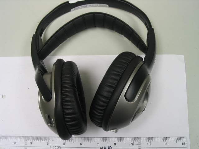
REDHP3390-001R
Aug 21, 2006900 MHz Receiver Headphone
Equipment Class
CYY - Communications Receiver used w/Pt 15 Transmitter
REDHP3390-001T
Aug 21, 2006900 MHz Wireless Headphone System - Transmitter
Equipment Class
DXX - Part 15 Low Power Communication Device Transmitter
REDMF400-001T
May 03, 2006Magnetic Field Wireless Backphone
Equipment Class
DXX - Part 15 Low Power Communication Device Transmitter
REDMF200-001T
May 03, 2006Magnetic Field Wireless Backphone
Equipment Class
DXX - Part 15 Low Power Communication Device Transmitter
REDHP2492-001R
Jan 29, 2006Wireless Headphone Receiver
Equipment Class
CYY - Communications Receiver used w/Pt 15 Transmitter