REDHP2791-001TWireless Headphone Transmitter
Classic Tech Development Ltd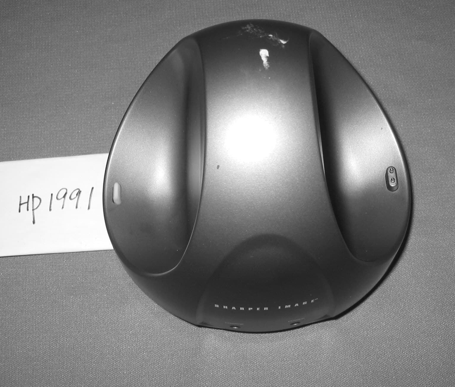
Click to zoom
Application Details
- Equipment Class
- DXX - Part 15 Low Power Communication Device Transmitter
- Date of Grant
- Jun 12, 2005
- Application Purpose
- Original Equipment
- Date of Application
- Jun 12, 2005
- Equipment Note
- Wireless Headphone Transmitter
- Frequency Range
- 912.00000000 - 913.00000000
- Company
- Classic Tech Development Ltd
- Country
- Hong Kong
Documents & Files
Document Text
Text extracted from the exhibit documents filed with the FCC. Open a document above to read the original.
Users Manual
HP2790 Cordless Stereo 900Mhz Headphone System User's Manual P. 2 INTRODUCTION This 900Mhz compact stereo headphone takes advantage of the very latest advances in wireless transmission technology and unique SRS surround effect so that you can listen to music or the sound from your TV set both in the house and outdoors. All you have to do is connect the transmitter to any audio source: DVD player, CD player, TV set, VCR, Hi-Fi system or radio (range 100 meters). FEATURES 1. SRS Surround Effect 2. Automatic Phases Lock Loop (PLL) scanning system on headphone 3. Phase Lock Loop (PLL) transmission system on transmitter 4. Automatic battery recharging (batteries supplied). 5. 900 MHz RF technology. 6. RF technology leaves you completely free to move around. 7. Transmission is not restricted solely to line of sight. 8. Rechargeable receiver headphones. 9. Charger built into the transmitter. 10. High quality stereo sound that is virtually interference-free. 11. Automatic Level Control (ALC) and Auto On/Off function. P. 3 COMPONENT IDENTIFICATION FRONT VIEW REAR VIEW P. 4 COMPONENT IDENTIFICATION 1 RF transmitter 2 RF receiver headphones 3 Power On/Off switch 4 Power On indicator light 5 Rechargeable 1.2 V 300 mAh batteries (Ni-Cd, LR03/AAA size) 6 Charge contacts 7 12V 150 mA mains adapter 8 Jack plug adapter (3.5 mm/6.3 mm diameter) 9 RCA socket audio adapter 10 Operating indicator light 11 Charge indicator light 12 Audio connection cable with 3.5 mm jack plug 13 Volume control knob (VOL) 14 AUTO SCAN indicator 15 AUTO SCAN button 16 DC IN connector 17 Audio input cable 18 Channel selector (CHANNEL 3 2 1) INSTALLATION TRANSMITTER 1. Connect the mains adapter provided to an electrical outlet. 2. Connect the mains adapter cable to the DC IN input connector located on the transmitter rear panel. P. 5 3. A cable is provided from the transmitter rear panel that can be connected to the audio outputs (Left and Right) present on a TV set, Hi-Fi system, VCR or radio-cassette player, or to a headphones/earphones output using the connector supplied. The red Auto On indicator light will light up as soon as you have connected the power adapter to the mains outlet and the audio cable to a signal source. If the Auto On indicator light remains off, switch on the audio source and increase its output level until the red indicator light comes on. HEADPHONE 1. Open the cover of the battery compartment located on the right hand receiver headphone. 2. Insert two rechargeable LR03/AAA size batteries taking care to ensure correct polarity. 3. Close the battery compartment cover. OPERATION 1. Switch on the sound source (TV set or audio component) that the transmitter is connected to. 2. Place the headphones On/Off switch in the On position. 3. Place the headphones on your head and adjust the volume to obtain the desired sound level. 4. If you cannot find the best reception frequency, press the "Auto Scan" button on the headphones. The corresponding indicator light will come on. 5. Press “SRS” button to activate Surround Effect for unique audio enjoyment. P. 6 NOTE: You should then be able to move around freely from one room to another without any interference. If interference does occur (interruptions in the signal), press the "Auto Scan" button once to find a better reception channel. A For better stereo reception, stay approximately seven meters away from the transmitter when you press the "Auto Scan" button. B If it is impossible to find a satisfactory frequency, change the setting on your transmitter, then press the "Auto Scan" button on the headphones to find the corresponding channel. To both protect the transmitter and save power, the transmitter automatically switches off after approximately one minute if the signal that it receives from the audio source is too weak for proper reception. If however the signal returns to an acceptable level, then the transmitter automatically switches back on. CHARGING THE BATTERIES 1. Place the On/Off switch on the receiver headphones in the Off position. 2. To recharge the headphone batteries, place the headphones on the transmitter, taking care to ensure that the charge contacts touch the transmitter's charge prongs. 3. The charge process starts automatically and the green indicator light comes on. Be sure to charge new batteries for 24 hours before using them for the first time in the headphones. P. 7 WARNING: Never attempt to recharge conventional dry cells. Never use another type of battery or non-rechargeable batteries to replace the rechargeable (LR03/AAA) batteries supplied. When the headphones are not in use, move the switch to the OFF position to avoid damaging the batteries. The batteries must always be fully charged before use. An initial 24 hour charge is required to guarantee an acceptable service life for the rechargeable batteries. Always ensure that the headphones are switched to the Off position while the batteries are charging. IMPORTANT: This unit can use both dry cells and rechargeable batteries. When replacing the batteries or when disposing of the unit, always comply with applicable laws relating to the disposal of batteries. Please place them in a proper disposal container to ensure that they are eliminated safely and in an environmentally-friendly way. Thank you. P. 8 REPLACING BATTERIES Rechargeable batteries have a long service life. If it is however necessary to replace them, proceed as described below: Only use rechargeable batteries of the type specified under the “Technical specifications” heading. The rechargeable batteries supplied with the headphones must absolutely not be taken apart, disposed of in an open fire or short circuited. Carefully remove the cloth padding around the left and right headphones. Install the new batter ies in their housings as illustrated. Check for correct +/- polarity. Bring the cloth padding up over the sloped guide slot. Hold it in place with your thumb just after the slope to ensure that it does not leave the guid…
Text truncated - open the document above for the full version.
External Photos
HP2791 external photo HP2791 external photo HP1991external photo HP1991 external photo HP2391 external photo
External Photos
HP2491 external photo HP2491 external photo HP2891 external photo HP2891 external photo
ID Label/Location Info
The FCC Label for HP2791 This Device complies with Part 15 of the FCC Rules. Operation of this device is subject to the following two conditions: (1) This device may not cause harmful interference, and (2) this device must accept any interference received, including interference that may cause undesired operation. WARNING: Modification of this device to receive cellular radio-telephone service signals is prohibited under FCC rules and Federal Law. FCC ID.: REDHP2791 – 001T The FCC Label for HP2792 This Device complies with Part 15 of the FCC Rules. Operation of this device is subject to the following two conditions: (1) This device may not cause harmful interference, and (2) this device must accept any interference received, including interference that may cause undesired operation. WARNING: Modification of this device to receive cellular radio-telephone service signals is prohibited under FCC rules and Federal Law. FCC ID.: REDHP2792 – 001R
ID Label/Location Info
The FCC Label for HP2791 This Device complies with Part 15 of the FCC Rules. Operation of this device is subject to the following two conditions: (1) This device may not cause harmful interference, and (2) this device must accept any interference received, including interference that may cause undesired operation. WARNING: Modification of this device to receive cellular radio-telephone service signals is prohibited under FCC rules and Federal Law. FCC ID.: REDHP2791 – 001T The FCC Label for HP2792 This Device complies with Part 15 of the FCC Rules. Operation of this device is subject to the following two conditions: (1) This device may not cause harmful interference, and (2) this device must accept any interference received, including interference that may cause undesired operation. WARNING: Modification of this device to receive cellular radio-telephone service signals is prohibited under FCC rules and Federal Law. FCC ID.: REDHP2792 – 001R
Internal Photos
HP2791, HP2391, HP2491, HP2691, HP2891 and HP1991 internal photo UHF module (Tx)
Test Report
Produktsicherheit und –qualität Product Safety and Quality Prüfbericht - Nr.: Test Report No.: 16004386 001 Seite 2 von 15 Page 2 of 15 TEST SUMMARY 5.1 CONDUCTED EMISSION FOR FCC PART 15 PER SECTION 15.207(A) RESULT: ok 5.2 RADIATED EMISSION FOR FCC PART 15 PER SECTION 15.209(A) RESULT: ok 5.3 FUNDAMENTAL AND HARMONICS RADIATED EMISSION FOR FCC PART 15 PER SECTION 15.249(A) RESULT: ok Produktsicherheit und –qualität Product Safety and Quality Prüfbericht - Nr.: Test Report No.: 16004386 001 Seite 3 von 15 Page 3 of 15 Contents 1 GENERAL REMARKS........................................................................................................... 4 1.1 COMPLEMENTARY MATERIALS......................................................................................... 4 2 TEST SITES.......................................................................................................................... 4 2.1 TEST FACILITIES................................................................................................................ 4 2.2 L IST OF TEST AND MEASUREMENT INSTRUMENTS........................................................... 5 2.3 TRACE ABILITY................................................................................................................... 5 2.4 CALIBRATION..................................................................................................................... 5 2.5 M EASUREMENT UNCERTAINTY......................................................................................... 6 2.6 L OCATION OF ORIGINAL DATA........................................................................................... 6 2.7 S TATUS OF FACILITY USED FOR TESTING........................................................................... 6 3 GENERAL PRODUCT INFORMATION................................................................................... 6 3.1 P RODUCT FUNCTION AND INTENDED USE......................................................................... 7 3.2 RATINGS AND SYSTEM DETAILS........................................................................................ 7 3.3 I NDEPENDENT OPERATION MODES................................................................................... 7 3.4 SUBMITTED DOCUMENTS................................................................................................... 8 4 TEST SET-UP AND OPERATION MODE............................................................................... 8 4.1 P RINCIPLE OF CONFIGURATION SELECTION..................................................................... 8 4.2 TEST OPERATION AND TEST SOFTWARE........................................................................... 8 4.3 S PECIAL ACCESSORIES AND AUXILIARY EQUIPMENT...................................................... 8 4.4 COUNTERMEASURES TO ACHIEVE EMC COMPLIANCE.................................................... 8 4.5 TEST SET-UP........................................................................................................................ 9 5 TEST RESULTS E MI S S I ON..................................................................................... 10 5.1 CONDUCTED EMISSION FOR FCC PART 15 PER SECTION 15.207(A) ............................. 10 5.2 RADIATED EMISSION FOR FCC PART 15 PER SECTION 15.209(A)................................. 11 5.3 FUNDAMENTAL AND HARMONICS RADIATED EMISSION FOR FCC PART 15 PER SECTION 15.249(A)....................................................................................................................................... 12 6 P HOTOGRAPHS OF THE TEST SET-UP.............................................................................. 13 7 L IST OF TABLES................................................................................................................ 15 8 LIST OF PHOTOGRAPHS.................................................................................................... 15 Produktsicherheit und –qualität Product Safety and Quality Prüfbericht - Nr.: Test Report No.: 16004386 001 Seite 4 von 15 Page 4 of 15 1 General Remarks 1.1 Complementary Materials All attachments are integral parts of this test report. This applies especially to the following appendix: Appendix 1: Test result 2 Test Sites 2.1 Test Facilities Shenzhen SMQ Shenzhen Bureau of Quality Technical Supervision Shenzhen Academy of Metrology and Quality Inspection Bldg, of Shenzhen Academy of Metrology and Quality Inspection Longzhu Road, Nanshan, Shenzhen, P.R. China Produktsicherheit und –qualität Product Safety and Quality Prüfbericht - Nr.: Test Report No.: 16004386 001 Seite 5 von 15 Page 5 of 15 2.2 List of Test and Measurement Instruments Table 1: List of Test and Measurement Equipment Kind of Equipment Manufacturer Type S/N Calibrated until Antenna Chase CBL6112B 2591 29.01.2006 Horn Antenna Rohde & Schwarz HF906 100014 29.01.2006 3m Semi-anechoic chamber Albatross Projects 9X6X6 ---- 29.01.2006 EMI Test Receiver Rohde & Schwarz ESI26 838786/013 29.01.2006 Communications Test Set Rohde & Schwarz CMU200 1100.0008.02 29.01.2006 Communications Test Set HP HP8920A 3438A05187 29.01.2006 EMI Test Receiver Rohde & Schwarz ESCS30 100003 29.01.2006 AMN Rohde & Schwarz ESH3-Z5 100002 29.01.2006 2.3 Trace ability All measurement equipment calibrations are traceable to NIST or where calibration is performed outside the United States, to equivalent nationally recognized standards organizations 2.4 Calibration Equipment requiring calibration is calibrated periodically by the manufacturer or according to manufacturer’s specifications. Additionally all equipment is verified for proper performance on a regular basis using in house standards or comparisons. Produktsicherheit und –qualität Product Safety and Quality Prüfbericht - Nr.: Test Report No.: 16004386 001 Seite 6 von 15 Page 6 of 15 2.5 Measurement Uncertainty The estimated combined standard uncertainty for conducted emissions measurements is ± 3 dB. The…
Text truncated - open the document above for the full version.
Test Setup Photos
Produktsicherheit und –qualität Product Safety and Quality Prüfbericht - Nr.: Test Report No.: 16004386 001 Seite 13 von 15 Page 13 of 15 6 Photographs of the Test Set-Up Photograph 1: Set-up for Conducted Emission on AC Mains Produktsicherheit und –qualität Product Safety and Quality Prüfbericht - Nr.: Test Report No.: 16004386 001 Seite 14 von 15 Page 14 of 15 Photograph 2: Set-up for Radiation Measurement Below 1GHz Photograph 3: Set-up for Radiation Measurement Above 1GHz
Contact Information
Applicant
Eric Chan(Project Manager)
Test Firm
Shenzhen Academy of Metrology & Quality InspectionPeter Lin
Technical Specifications
| # | Rule Parts | Frequency Range | Power Output |
|---|---|---|---|
| 1 | 15C | 912 MHz - 913 MHz | - |
Other Applications from Classic Tech Development Ltd
REDHP3390-001R
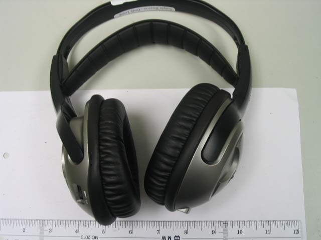
Aug 21, 2006900 MHz Receiver Headphone
Equipment Class
CYY - Communications Receiver used w/Pt 15 Transmitter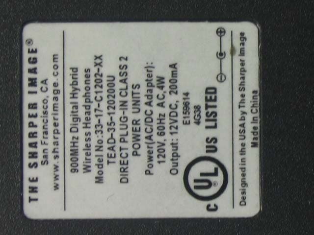
REDHP3390-001T
Aug 21, 2006900 MHz Wireless Headphone System - Transmitter
Equipment Class
DXX - Part 15 Low Power Communication Device Transmitter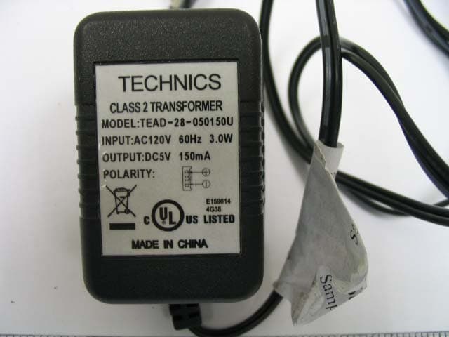
REDMF400-001T
May 03, 2006Magnetic Field Wireless Backphone
Equipment Class
DXX - Part 15 Low Power Communication Device Transmitter
REDMF200-001T
May 03, 2006Magnetic Field Wireless Backphone
Equipment Class
DXX - Part 15 Low Power Communication Device Transmitter
REDHP2492-001R
Jan 29, 2006Wireless Headphone Receiver
Equipment Class
CYY - Communications Receiver used w/Pt 15 Transmitter