REDSP1092-001RWireless Speaker Receiver
Classic Tech Development Ltd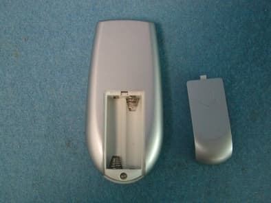
Click to zoom
Application Details
- Equipment Class
- CYY - Communications Receiver used w/Pt 15 Transmitter
- Date of Grant
- May 16, 2004
- Application Purpose
- Original Equipment
- Date of Application
- May 16, 2004
- Equipment Note
- Wireless Speaker Receiver
- Frequency Range
- 912.03000000 - 913.03000000
- Company
- Classic Tech Development Ltd
- Country
- Hong Kong
Documents & Files
Document Text
Text extracted from the exhibit documents filed with the FCC. Open a document above to read the original.
Users Manual
SP1090 Cordless 900MHZ Speaker System User’s Manual Please read before using the equipment P. 1 INTRODUCTION This 900 MHz wireless speaker system uses latest wireless technology that enables you to enjoy music and TV sound anywhere inside or outside your home. You can simply connect the system to any audio source such as Radio, TV, VCR, Hi-Fi and CD/MP3/VCD/DVD player. Without complicated wiring and installation with your Audio/Video equipments and rear channel amplifier, the system enables you to enjoy thrilling, lifelike sound in minutes. FEATURES 1. Automatic Phases Lock Loop (PLL) scanning system on speaker receivers 2. Phase Lock Loop (PLL) transmission system on transmitter 3. 900 MHz RF technology panel-like speaker system. 4. RF technology lets you roam freely throughout your house. 5. Operating distance up to 150 feet. 6. No line of sight limitation. 7. Virtually interference free audio quality. 8. Auto ON/OFF control. 9. Auto tuning function. 10. Remote control unit P. 2 COMPONENT IDENTIFICATION TRANSMITTER SPEAKER RECEIVERS Antenna Power on indicator (Blue) P. 3 REMOTE CONTROL INSTALLATION TRANSMITTER 1. Insert the antenna tube into the antenna wire. 2. Connect the supplied AC/DC power adaptor to an electrical wall outlet. 3. Plug the AC/DC power adaptor in the DC jack located on the rear of the transmitter. 4. The rear of the transmitter has one audio cord that can be connected to audio output jack of TV, Monitor, VCR, Radio recorder, CD/MP3/VCD/DVD players or to headphone/earphone jack with the connector provided. Plug the adaptor in the AC source and connect the audio plug to the audio source. As soon as the transmitter is receiving the audio signal, it will automatically switch on and the blue LED will light up. P. 4 SPEAKER RECEIVERS 1. Insert 6 pieces ‘C’ size ALKALINE battery into the battery compartment with correct polarity at the bottom of the speakers (batteries not included in the package) or connect the 12V power adaptor to the DC input jack on the bottom of each speaker, then plug it to the wall AC outlet. 2. Press On/Off button and turn the speakers ON. The POWER LED will light up in Blue. Switch off the speakers by pressing the ON/OFF button on the speaker or on the remote control unit, and the LED will be off. P. 5 REMOTE CONTROL UNIT 1. Remove the battery cover at the rear of the remote control unit and insert 2 pieces “AAA” size battery provided into the battery compartment with the correct polarity. 2. Place back the cover and close the battery compartment. OPERATION 1. Turn on the audio source (TV or audio component) to which the transmitter is connected with. The Blue LED on the transmitter will light up. 2. Select the channel 1 or 2 of the transmitter for best performance in your location. 3. Turn on the ON/OFF button on the speaker (the ON/OFF button on the remote control unit cannot be used as a primary device to switch on the speakers). Press the “AUTO TUNE” button to get the best tuning reception in the speakers. When the button is pressed, frequency tuning starts automatically and it stops when a signal is detected. Tuning process can also be activated by pressing the “AUTO TUNE” button on the remote control unit. 4. Volume can be adjusted up by pressing “+” button or down by pressing the button “-“ to the desired listening level, or you can press the “+” button or “-“ button” on the remote control unit to adjust the volume level. NOTE : a). Keep a distance of the speaker up to 7 meters apart from the transmitter, and then press “AUTO TUNE” button for the best reception. P. 6 b) Whenever you find frequency jam, move your channel switch from one channel to the other channel (there are two channels for selection) on the transmitter, and then press the “AUTO-TUNE” button again. 5. You should now be able to place the speakers freely from room to room without disruption. Should there is any disruption (signal cuts off or carries distortion), press the speaker’s “AUTO TUNE” button to maximize the best reception. If you hear interference from other components, switch on the channel control of transmitter, and then move the speakers to other free location. You can re-adjust the tuning control by moving it either channel 1 or 2 of the transmitter, then pressing “AUTO TUNE” button for best reception. When transmitting / receiving over long distances, the signal from the system will become weaker. 6. Switching Off a) For protection of the transmitter and power saving, the transmitter will cut off automatically if there is P. 7 no/weak operation input signal from audio source for 4 minutes. In other words, if the signal comes back, the transmitter will work again automatically. b) Press the ON/OFF button to turn off the speaker and the LED light goes off, or simply press the ON/OFF button on the remote control unit. If you use the remote control unit to turn off the speaker, the speaker will be at stand-by mode for 5 minutes and the LED will be changed from blue to green. You can switch on the speaker again by using the remote control unit during the stand-by time. If there is no signal from the remote control unit in 5 minutes, the speaker will automatically power off. TROUBLE SHOOTING NO SOUND - Ensure the AC/DC adaptor is fully inserted into the AC outlet and the power connection input on the transmitter. - Ensure the speaker is switch ON. - Speaker’s battery capacity is too low, replace with new batteries or connect the AC/DC adaptors to the speakers. - Ensure the TV or audio component is ON. - The connected audio / video equipment is not playing. Start playing the equipment. - The volume of speaker is too low, adjust the volume to an appropriate level. DISTORTED - Press the “AUTO-TUNE” button on the speakers until matching the frequency of the transmitter. - Change the position of the channel selector on the transmitter. You must then press the “AUTO TUNE” button on the speakers. - Battery capacity is too low. Replace with the new battery. - Ensure the vol…
Text truncated - open the document above for the full version.
External Photos
External photos for SP1092 External photos for SP1092 External photos for SP1092 External photos for SP1092
ID Label/Location Info
The FCC Label for SP1092 This Device complies with Part 15 of the FCC Rules. Operation of this device is subject to the following two conditions: (1) This device may not cause harmful interference, and (2) this device must accept any interference received, including interference that may cause undesired operation. WA R N I N G : Modification of this device to receive cellular radio-telephone service signals is prohibited under FCC rules and Federal Law. FCC ID: REDSP1092 – 001R
Internal Photos
Internal photos for SP1092 Internal photos for SP1092 Internal photos for SP1092 Internal photos for SP1092
Test Setup Photos
Produktsicherheit und –qualität Product Safety and Quality Prüfbericht - Nr.: Test Report No.: 16002858 001 Seite 15 von 17 Page 15 of 17 6 Photographs of the Test Set-Up Photograph 1: Set-up for Conducted Emission on AC Mains Photograph 2: Set-up for Radiation Measurement Below 1GHz Produktsicherheit und –qualität Product Safety and Quality Prüfbericht - Nr.: Test Report No.: 16002858 001 Seite 16 von 17 Page 16 of 17 Photograph 3: Set-up for Radiation Measurement Above 1GHz
Contact Information
Applicant
Eric Chan(Project Manager)
Test Firm
Shenzhen Academy of Metrology & Quality InspectionPeter Lin
Technical Specifications
| # | Rule Parts | Frequency Range | Power Output |
|---|---|---|---|
| 1 | 15B | 912.03 MHz - 913.03 MHz | - |
Other Applications from Classic Tech Development Ltd
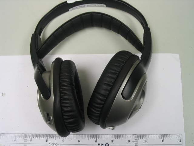
REDHP3390-001R
Aug 21, 2006900 MHz Receiver Headphone
Equipment Class
CYY - Communications Receiver used w/Pt 15 Transmitter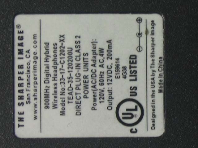
REDHP3390-001T
Aug 21, 2006900 MHz Wireless Headphone System - Transmitter
Equipment Class
DXX - Part 15 Low Power Communication Device Transmitter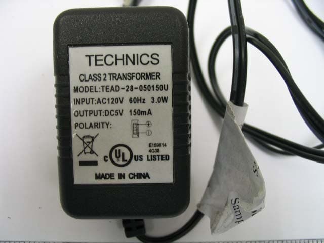
REDMF400-001T
May 03, 2006Magnetic Field Wireless Backphone
Equipment Class
DXX - Part 15 Low Power Communication Device Transmitter
REDMF200-001T
May 03, 2006Magnetic Field Wireless Backphone
Equipment Class
DXX - Part 15 Low Power Communication Device Transmitter
REDHP2492-001R
Jan 29, 2006Wireless Headphone Receiver
Equipment Class
CYY - Communications Receiver used w/Pt 15 Transmitter