REDSP1291-001TAudio Transmitter
Classic Tech Development Ltd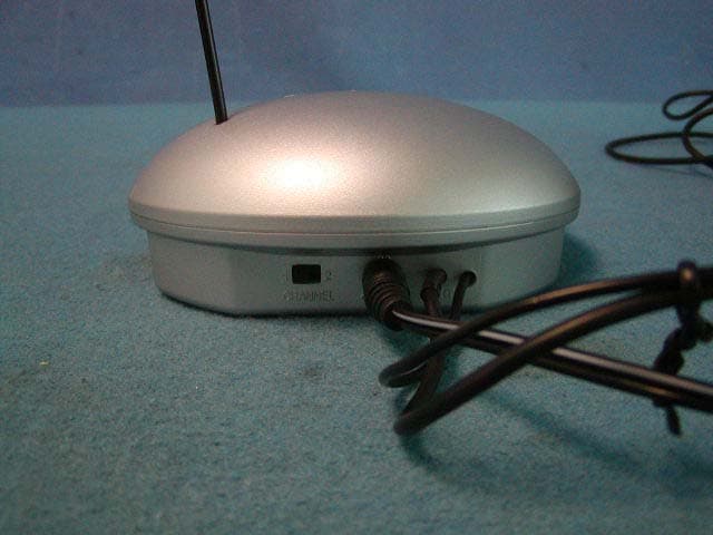
Click to zoom
Application Details
- Equipment Class
- DXX - Part 15 Low Power Communication Device Transmitter
- Date of Grant
- Jun 17, 2004
- Application Purpose
- Original Equipment
- Date of Application
- Jun 17, 2004
- Equipment Note
- Audio Transmitter
- Frequency Range
- 912.00000000 - 913.00000000
- Company
- Classic Tech Development Ltd
- Country
- Hong Kong
Documents & Files
Document Text
Text extracted from the exhibit documents filed with the FCC. Open a document above to read the original.
Users Manual
SP1290 (SP1291 + SP1292 + HP1294) 900MHz Wireless Combo Speaker with Headphone P. 1 User’s Manual Please read before using the equipment P. 2 INTRODUCTION This 900 MHz wireless combo speaker system with headphone uses the latest wireless technology that enables you to enjoy music and TV sound anywhere inside your home. You can simply connect the system to any audio source such as Radio, TV, VCR, Hi-Fi and CD/MP3/VCD/DVD player. Without complicated wiring and installation with your Audio/Video equipments and rear channel amplifier, the system enables you to enjoy thrilling, lifelike sound in minutes. FEATURES 1. Automatic Phases Lock Loop (PLL) scanning system on speakers. 2. Automatic Phases Lock Loop (PLL) scanning system on headphone. 3. Phase Lock Loop (PLL) transmission system on transmitter. 4. 900 MHz RF technology. 5. Operating distance up to 150 feet for both speakers and headphone. 6. No line of sight limitation. 7. Virtually interference free audio quality. 8. Auto ON/OFF control on the transmitter. 9. Auto-scan function on speakers. 10. Auto-scan function on headphone IMPORTANT SAFETY INFORMATION 1. Read and understand all the instructions before using the product. 2. Follow all the warning and instructions. 3. Before placing headphones on head, ensure that the volume is at a comfortable level. 4. Reduce the volume or discontinue use if you experience a ringing in your ears. 5. Do not use liquid or aerosol cleaners. Use a damp cloth for cleaning. If necessary, use a mild soap. 6. Do not use this product near water, for example, near a bathtub or laundry tub, in a wet basement, or near a swimming pool. 7. Avoid exposing this product to high heat from any source. P. 3 8. Do not place this product on an unstable cart, stand or table. The product may fall, causing serious damage. 9. Do not allow anything to rest on the AC/DC adapter cord or AUDIO IN cable. Do not place this product where the cord can be abused by animals or people walking on it. 10. Never push objects of any kind into this product through the cabinet slots as they may touch dangerous voltage points or short cut parts that could result in a risk of fire or electric shock. Never spill any kind of liquid on the product. 11. To reduce the risk of electric shock, do not disassemble this product. Opening or removing covers may expose you to dangerous electric shock when the product is subsequently used. 12. Do not attempt to repair, or modify the product. Take it to a qualified service center when service is required. 13. Unplug this product from the wall outlet and refer to qualified service personnel under the following conditions: a. If liquid has been spilled into the product. b. If the product has been exposed to rain or water. c. If the product does not operate normally by following the operating instructions. Adjust only the controls that are covered by the operating instructions because improper adjustment of other controls may result in damage if the product has been dropped or the cabinet has been damaged. P. 4 COMBO SYSTEM PART LIST DIAGRAMS & NUMBERING A) TRANSMITTER B) SPEAKER RECEIVER C) HEADPHONE RECEIVER D) ACCESSORIES P. 5 COMBO SYSTEM PART LIST IDENTIFICATION Parts Identification: A: Transmitter 1. Power On/Off Indicator. 2. Audio cable. 3. Charging cable. 4. Channel selector (channel 2-1) 5. DC IN socket. 6. Antenna. B. Speakers 7. Power ON/Off Indicator. 8. Volume control/ Power ON/OFF. 9. Normal/Boost Bass. 10. Auto Scan Button. 11. DC IN socket. 12. Battery Door. 13. Supporting Stands. C. Headphone 14. Volume Control. 15. ON/OFF Control. 16. Battery compartment. 17. Power LED indicator. 18. Auto-Scan Control. 19. Auto-Scan LED indicator. 20. Charging jack. D. Accessories 21. AC/DC adapter (1 x 12.5V 150mA for transmitter). 22. AC/DC adapter (2 x 12V 500mA for speakers). 23. 3.5mm to 6.3 mm adapter plug. 24. RCA adapter. 25. Antenna tube. P. 6 26. Two rechargeable batteries (AAA size). INSTALLATION TRANSMITTER 1. Insert the antenna tube into the antenna wire. 2. Connect the supplied AC/DC power adapter to an electrical wall outlet. 3. Plug the AC/DC power adapter in the DC jack located on the rear of the transmitter. 4. The rear of the transmitter has one audio cord that can be connected to audio output jack of TV, Monitor, VCR, Radio recorder, CD/MP3/VCD/DVD players or to headphone/earphone jack with the connector provided. Plug the adapter in the AC source and connect the audio plug to the audio source. As soon as the transmitter is receiving the audio signal, it will automatically switch on and the green LED will light up. SPEAKER RECEIVER 1. Insert 6 pieces “AA” size ALKALINE battery into the battery compartment with correct polarity at the rear of the speaker OR connect the 12V power adapters to the DC input jacks on the rear of each speaker, then plug it to the wall AC outlet. 2. Press On/Off button and turn the speaker ON. The POWER LED will light up in red. Switch off the speaker by pressing the ON/OFF button on the speaker, and the LED will be off. P. 7 WIRELESS HEADPHONE 1. Open the battery compartment cover on the right side of the headphone. 2. Insert 2pcs of AAA size rechargeable batteries (supplied in the package) by matching the + and – on the battery to the diagram inside the battery compartment. 3. Close the battery compartment by sliding the battery compartment cover back into place. OPERATION -Turn on the audio source (TV or audio component) to which the transmitter is connected with. The red LED on the transmitter will light up. -Select the channel 1 or 2 of the transmitter. P. 8 For Speakers 1. Turn on the ON/OFF button on the speakers. Press the “AUTO-SCAN” button to get the best tuning reception in the speakers. When the button is pressed, frequency tuning starts automatically and it stops when a signal is detected. 2. Volume can be adjusted up by tuning the volume knob on the right sides of the speakers to the desired listening level. 3. Whenever you find frequency jam, move …
Text truncated - open the document above for the full version.
External Photos
SP1291 external photo
ID Label/Location Info
The FCC Label for SP1291 This Device complies with Part 15 of the FCC Rules. Operation of this device is subject to the following two conditions: (1) This device may not cause harmful interference, and (2) this device must accept any interference received, including interference that may cause undesired operation. FCC ID: REDSP1291 – 001T
ID Label/Location Info
Transmitter SP1291
Internal Photos
SP1291 internal photo
Internal Photos
SP1291 internal photo solder side
Operational Description
Page 1 of 1 Product Operation Description This product is a 900MHz transmitter, which is stereo wireless Headphone system (via Headphone) or Speaker system (via Speaker) for audio usage, they would be operated with its associated receiver (Headphone or Speaker), with one AC/DC adaptor PC-1255-DUA (120VAC to 12VDC, 550mA). The main function of SP1291 is modulating the audio signal, transmit RF signal to associated receiver. The operating frequency of SP1291 is 912.03MHz and 913.03MHz; the transmitting frequency can be selected by pushing the channel-selective button, which was equipped at the side of SP1291’s body. SP1291 consists of indicating light (colour in Green during transmitting or colour in red during charging). On the other hand, the DC jack and the audio in jacks are used for DC power connection and connecting to an audio source respectively. Moreover, the transmitter SP1291 includes an additional charging line for headphone’s batteries charging.
Test Report
Produktsicherheit und –qualität Product Safety and Quality Seite 2 von 16 Prüfbericht - Nr.: Test Report No.: 16002954 001 Page 2 of 16 TEST SUMMARY 5.1 CONDUCTED EMISSION FOR FCC PART 15 PER SECTION 15.207(A) RESULT: ok 5.2 RADIATED EMISSION FOR FCC PART 15 PER SECTION 15.209(A) RESULT: ok 5.3 FUNDAMENTAL AND HARMONICS RADIATED EMISSION FOR FCC PART 15 PER SECTION 15.249(A) RESULT: ok Produktsicherheit und –qualität Product Safety and Quality Seite 3 von 16 Prüfbericht - Nr.: Test Report No.: 16002954 001 Page 3 of 16 Contents 1 GENERAL REMARKS........................................................................................................... 4 1.1 COMPLEMENTARY MATERIALS......................................................................................... 4 2 TEST SITES.......................................................................................................................... 4 2.1 TEST FACILITIES................................................................................................................ 4 2.2 LIST OF TEST AND MEASUREMENT INSTRUMENTS........................................................... 5 2.3 TRACE ABILITY................................................................................................................... 5 2.4 CALIBRATION..................................................................................................................... 5 2.5 MEASUREMENT UNCERTAINTY.......................................................................................... 6 2.6 LOCATION OF ORIGINAL DATA........................................................................................... 6 2.7 STATUS OF FACILITY USED FOR TESTING........................................................................... 6 3 GENERAL PRODUCT INFORMATION................................................................................... 6 3.1 PRODUCT FUNCTION AND INTENDED USE......................................................................... 7 3.2 RATINGS AND SYSTEM DETAILS........................................................................................ 7 3.3 INDEPENDENT OPERATION MODES................................................................................... 7 3.4 SUBMITTED DOCUMENTS................................................................................................... 8 4 TEST SET-UP AND OPERATION MODE............................................................................... 8 4.1 P RINCIPLE OF CONFIGURATION SELECTION..................................................................... 8 4.2 TEST OPERATION AND TEST SOFTWARE........................................................................... 8 4.3 S PECIAL ACCESSORIES AND AUXILIARY EQUIPMENT....................................................... 8 4.4 C OUNTERMEASURES TO ACHIEVE EMC COMPLIANCE.................................................... 8 4.5 T EST SET-UP........................................................................................................................ 9 5 TEST RESULTS E M I S S I O N ..................................................................................... 11 5.1 CONDUCTED EMISSION FOR FCC PART 15 PER SECTION 15.207(A) ............................. 11 5.2 RADIATED EMISSION FOR FCC PART 15 PER SECTION 15.209(A)................................. 12 5.3 F UNDAMENTAL AND HARMONICS RADIATED EMISSION FOR FCC PART 15 PER SECTION 15.249(A)....................................................................................................................................... 13 6 PHOTOGRAPHS OF THE TEST SET-UP.............................................................................. 14 7 LIST OF TABLES................................................................................................................ 16 8 L IST OF PHOTOGRAPHS.................................................................................................... 16 Produktsicherheit und –qualität Product Safety and Quality Seite 4 von 16 Prüfbericht - Nr.: Test Report No.: 16002954 001 Page 4 of 16 1 General Remarks 1.1 Complementary Materials All attachments are integral parts of this test report. This applies especially to the following appendix: Appendix 1: Test result 2 Test Sites 2.1 Test Facilities Shenzhen SMQ Shenzhen Bureau of Quality Technical Supervision Shenzhen Academy of Metrology and Quality Inspection Bldg, of Shenzhen Academy of Metrology and Quality Inspection Longzhu Road, Nanshan, Shenzhen, P.R. China Produktsicherheit und –qualität Product Safety and Quality Seite 5 von 16 Prüfbericht - Nr.: Test Report No.: 16002954 001 Page 5 of 16 2.2 List of Test and Measurement Instruments Table 1: List of Test and Measurement Equipment Kind of Equipment Manufacturer Type S/N Calibrated until Antenna Chase CBL6112B 2591 29.01.2005 Horn Antenna Rohde & Schwarz HF906 100014 29.01.2005 3m Semi-anechoic chamber Albatross Projects 9X6X6 ---- 29.01.2005 EMI Test Receiver Rohde & Schwarz ESI26 838786/013 29.01.2005 Communications Test Set Rohde & Schwarz CMU200 1100.0008.02 29.01.2005 Communications Test Set HP HP8920A 3438A05187 29.01.2005 EMI Test Receiver Rohde & Schwarz ESCS30 100003 29.01.2005 AMN Rohde & Schwarz ESH3-Z5 100002 29.01.2005 2.3 Trace ability All measurement equipment calibrations are traceable to NIST or where calibration is performed outside the United States, to equivalent nationally recognized standards organizations 2.4 Calibration Equipment requiring calibration is calibrated periodically by the manufacturer or according to manufacturer’s specifications. Additionally all equipment is verified for proper performance on a regular basis using in house standards or comparisons. Produktsicherheit und –qualität Product Safety and Quality Seite 6 von 16 Prüfbericht - Nr.: Test Report No.: 16002954 001 Page 6 of 16 2.5 Measurement Uncertainty The estimated combined standard uncertainty for conducted emissions measurements is ± 3 dB. Th…
Text truncated - open the document above for the full version.
Test Setup Photos
Produktsicherheit und –qualität Product Safety and Quality Seite 14 von 16 Prüfbericht - Nr.: Test Report No.: 16002954 001 Page 14 of 16 6 Photographs of the Test Set-Up Photograph 1: Set-up for Conducted Emission on AC Mains Photograph 2: Set-up for Radiation Measurement Below 1GHz Produktsicherheit und –qualität Product Safety and Quality Seite 15 von 16 Prüfbericht - Nr.: Test Report No.: 16002954 001 Page 15 of 16 Photograph 3: Set-up for Radiation Measurement Above 1GHz
Contact Information
Applicant
Eric Chan(Project Manager)
Test Firm
Shenzhen Academy of Metrology & Quality InspectionPeter Lin
Technical Specifications
| # | Rule Parts | Frequency Range | Power Output |
|---|---|---|---|
| 1 | 15C | 912 MHz - 913 MHz | - |
Other Applications from Classic Tech Development Ltd
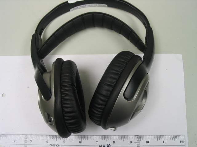
REDHP3390-001R
Aug 21, 2006900 MHz Receiver Headphone
Equipment Class
CYY - Communications Receiver used w/Pt 15 Transmitter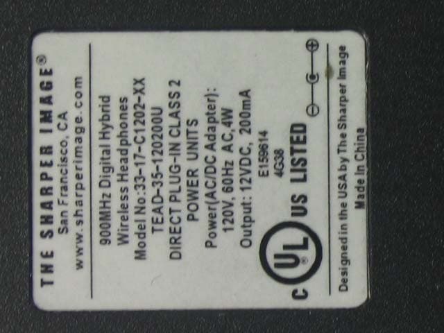
REDHP3390-001T
Aug 21, 2006900 MHz Wireless Headphone System - Transmitter
Equipment Class
DXX - Part 15 Low Power Communication Device Transmitter
REDMF400-001T
May 03, 2006Magnetic Field Wireless Backphone
Equipment Class
DXX - Part 15 Low Power Communication Device Transmitter
REDMF200-001T
May 03, 2006Magnetic Field Wireless Backphone
Equipment Class
DXX - Part 15 Low Power Communication Device Transmitter
REDHP2492-001R
Jan 29, 2006Wireless Headphone Receiver
Equipment Class
CYY - Communications Receiver used w/Pt 15 Transmitter