REJGDR908.65 to 915.95 MHz Station Side/Transceiver
Go Direct International, Ltd.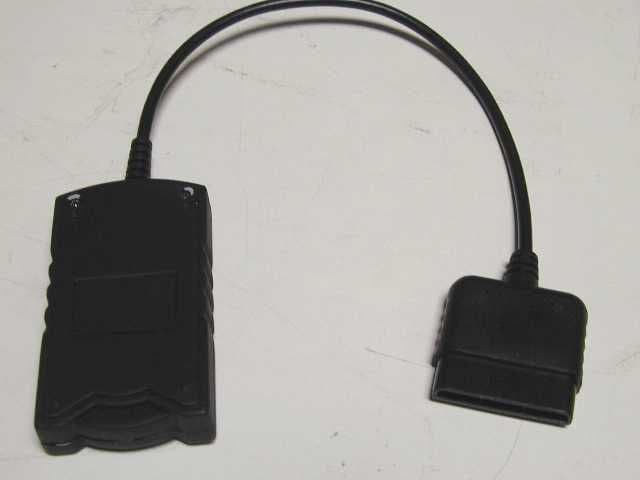
Click to zoom
Application Details
- Equipment Class
- DXT - Part 15 Low Power Transceiver, Rx Verified
- Date of Grant
- Sep 28, 2003
- Application Purpose
- Original Equipment
- Date of Application
- Sep 28, 2003
- Equipment Note
- 908.65 to 915.95 MHz Station Side/Transceiver
- Frequency Range
- 908.65000000 - 915.95000000
- Country
- Hong Kong
Documents & Files
Document Text
Text extracted from the exhibit documents filed with the FCC. Open a document above to read the original.
Users Manual
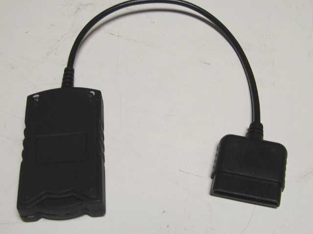
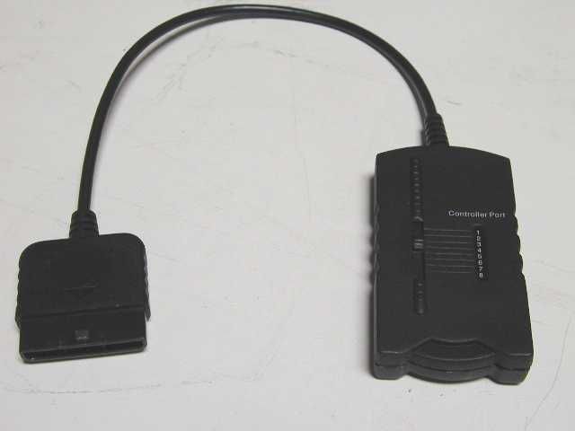
Congratulations! You have purchased the advanced RF Wireless video game controller. The RadioWave TM was designed by a group of PhD's in RF technology that has developed specialized RF communications for NASA. The RadioWave TM has all the same features of the original controller, but with wireless game play up to 25 feet. Please read the following operation instructions before using the RadioWave TM . RadioWave Operating Instructions PRODUCT FEATURES • Analog pressure sensitive compatible • Multi-tap compatible • SMART CHANNEL automatically finds the optimal RF channel for each RadioWave TM . • Advanced embedded antenna • Power On button powers on RadioWave TM . • Auto power off when button not pressed for 10 minutes • Vibration On/Off function, allows you to manually turn motors off to conserve battery power. (Vibration function default is On). • Low battery indicator, Analog LED will flash; • Shuts down automatically when PlayStation ̈ is shut off or Receiver is removed from PlayStation® port. CONTROLLER FUNCTION DESCRIPTIONS (see figure 1) 1. START/SELECT • Start button to start and pause the game • Select button for menu function during game play 2. ACTION BUTTONS • All fire buttons are Analog Pressure sensitive compatible. 3. ANALOG JOYSTICKS • Left Analog Joy Stick (Press down for L3 button function) • Right Analog Joy Stick (Press down for R3 button function) • Designed for precise control of analog game play 4. ANALOG BUTTON with LED INDICATOR • Activates controller analog mode, LED turns on 5. LOW BATTERY INDICATOR • Analog LED will flash when battery life is low 6. DIRECTION PAD • Exclusive thumb-pad design for fast game control 7. SHOULDER FIRE BUTTONS L1, L2, R1, R2 Additional action buttons 8. POWER ON BUTTON & VIBRATION ON/OFF FUNCTION • "Power On" button activates controller, vibration motors will activate. If desired Press "Power On" button for 3 seconds to turn vibration Off to Conserve battery life. (Vibration default is On) 9. SLEEP MODE RadioWave TM will shut off after 10 minutes of non-use to conserve battery life. OPERATING INSTRUCTIONS 1. Connecting the Receiver: The RadioWave TM Dual Analog wireless controller includes a "Receiver" device that must connect to the PlayStation® controller port for the controller to function. Once the Receiver is installed properly there is no need to disconnect it from the PlayStation ̈ when not is use. The RadioWave TM power is shut of f automatically when the PlayStation® console is powered of f. (Please read on for the Receiver installation procedure). 2 Controller Port switch on the Receiver: The Controller Port switch located on the RadioWave TM receiver must match the player Port number on the PlayStation® console it is plugged into to operate properly. For Player 1 Set the "Controller Port" switch to 1 and plug the Receiver into Controller Port 1 on the PlayStation® Console. For Player 2 set the "Controller Port" switch to 2 and plug the Receiver into Controller Port 2 on the PlayStation ̈ Console. (see figure 2) 3. PLAYER ORDER: WHEN USING MORE THAN ONE RADIOWAVE CONTROLLER, WAIT 5 SECONDS BEFORE POWERING ON EACH PLAYERS CONTROLLER, THIS WILL ALLOW EACH CONTROLLER TO LINK UP WITH THE RECEIVERS STARTING FROM PLAYER 1, THEN PLAYER 2 AND SO ON. THE FIRST CONTROLLER TURNED ON WILL BE PLAYER 1, THE SECOND CONTROLLER TURNED ON WILL BE PLAYER 2. IF THE RADIOWAVE TM CONTROLLERS ARE TURNED OFF OR GO INTO SLEEP MODE AFTER 10 MINUTES OF NON-USE, YOU WILL NEED TO PRESS THE POWER ON BUTTON AGAIN ON THE CONTROLLERS. THE FIRST CONTROLLER POWERED ON WILL THEN BECOME PLAYER 1, THE SECOND PLAYER 2. Radio Wave Manual Color: Black Size: 400 X 185 mm Date: 06 Aug 03 LIMITED WARRANTY SYLVANIA ADVANCED TECHNOLOGIES warrants this products to be free from defects in material and manufacture for a period of 90 days from the date of original purchase by the consumer. This warranty is conditional that the product has been installed and used according to the instructions and has not been abused physically or damaged due to accident or misuse. Should the product prove to be defective during this period, return it for exchange to the store of original purchase. shall not be liable for any loss or damage, direct, indirect or consequential, arising out of the use or inability to use this product. (Some status do not allow limitations or implied warranties or exclusion of consequential damage, therefore, these restrictions may not apply to you.) This warranty gives these specific legal rights. You may have other rights that vary from state to state. Licensed by Sony Computer Entertainment America Inc. "PlayStation" and the "PS" Family logos are registered trademarks and PS one is a trademark of Sony Computer Entertainment Inc. RadioWave TM is trademark of Go Direct International Limited is a registered trademark of OSRAM SYLVANIA Inc. used under license. UNICAL ENTERPRISES, INC. 16960 Gale Avenue, City of Industry, CA 91745, USA © COPYRIGHT 2002 - ALL RIGHTS RESERVED www.theyesalliance.com www.unical-usa.com Figure 2: Figure 1: IMPORTANT: THE RECEIVER SHOULD BE PLUGGED INTO THE PLAYSTATION® PORT BEFORE POWERING ON THE RADIOWAVE TM CONTROLLER. • Connection: Make sure that all receivers are fully inserted into the PlayStation® controller ports and make sure the Controller Switch located on the Receiver is set to the same number Port on the PlayStation® console. (See figure 2 and 3) • Power: Make sure that the "Power On" button has been pressed; Vibration will activate to indicate RadioWave TM is operational. If vibration does not activate, try installing new batteries. • RF Interference: The RadioWave TM Smart Channel feature will choose a dedicated frequency for the RF communication between the RadioWave TM controller and PlayStation® console Receiver. However, should the controller operation become inconsistent during game play, unplug and plug the Receiver back into the PlayStation® console and press the Power on button on the RadioWave TM to allow the Smar…
Text truncated - open the document above for the full version.
Block Diagram
Biswave Confidential: Reproduction Restricted Video Game Wireless Dongle Block Diagram Bitswave Confidential August 12, 2003 Biswave Confidential: Reproduction Restricted Operating Frequencies FCC Units Fundamental Transmit Frequencies (MHz) Ch. No.12345678 Freq. (MHz) 908.584 909.638 910.691 911.744 912.797 913.851 914.904 915.957 Biswave Confidential: Reproduction Restricted Station Side Connectorto videogamemachine Microprocessor RF radio modem LCFilter FrequencySynthesizer andPLL RSSIMeasurement DC power 14.7456 MHz Xtal 4 MHz Xtal
Block Diagram
Biswave Confidential: Reproduction Restricted Video Game Wireless Dongle Block Diagram Bitswave Confidential August 12, 2003 Biswave Confidential: Reproduction Restricted Operating Frequencies FCC Units Fundamental Transmit Frequencies (MHz) Ch. No.12345678 Freq. (MHz) 908.584 909.638 910.691 911.744 912.797 913.851 914.904 915.957 Biswave Confidential: Reproduction Restricted Station Side Connectorto videogamemachine Microprocessor RF radio modem LCFilter FrequencySynthesizer andPLL RSSIMeasurement DC power 14.7456 MHz Xtal 4 MHz Xtal
Cover Letter(s)
REJGDRRadioWave Receiver 1) Electrical Schematics of the Circuitry
Cover Letter(s)
REJGDRRadioWave Receiver 1) Electrical Schematics of the Circuitry
Operational Description
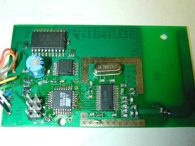
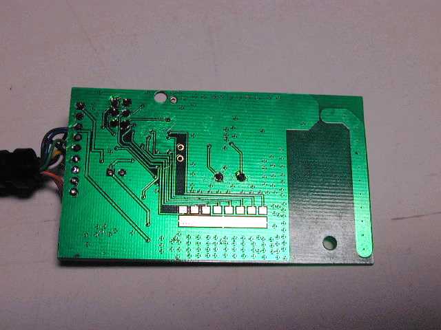
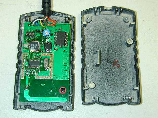
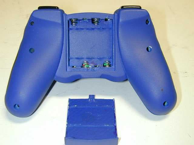
Wireless Joypad for Sony PlayStation Theory of Operation 8/8/03 Bitswave, Inc. 1. Station Side Radio The radio system is mainly composed of three parts: radio modem, frequency synthesizer and baseband microprocessor. The radio is interfaced with Sony PlayStation via a 9-pin connector. Sony PayStation sends a command to the radio every 16 milliseconds. The radio takes the data from PlayStation, packetize the data by adding preambles, frame information, and error checking bytes. The packetized frame is transmitted to the wireless joystick. When joystick replies, this radio receives the data, un-packetize it, and sends to Sony PlayStation. The radio modem is a FSK modem running at 36.8 kbps with Manchester encoding to avoid frequency drifting. Frequency is controlled by a frequency synthesizer which adjusts a voltage-controlled RF oscillator dynamically for accurate frequency management. Channel is set by selecting an 8-position slide switch. A total of 8 channels can be selected conversing the frequency range of 908 - 915 MHz. The antenna is an embedded PCB antenna matching is done by using lumped inductors and capacitors. The radio is a half-duplex system and is powered by a 3.3V power source provided by Sony PlayStation. The total average power consumption of the radio system is about 20 mA at 3.3V. 2. Joypad Side Radio Joypad side radio operates in similar way to Station Side Radio as described in previous section. However, this radio works as a slave compared to the Station Side Radio. When powered on, this radio is in receiving mode and waits until a command from Station Side Radio is received. It scans keystrokes on the joypad and replies the command with the keystroke data to the Station Side Radio. Similarly, the data is packetized in the same way as Station Side Radio. The joypad radio is powered by 4-AAA side batteries and down regulated to 3.3V. Another power regulator (3.0V) provides power for two vibration motors in the joypad.
Operational Description
Wireless Joypad for Sony PlayStation Theory of Operation 8/8/03 Bitswave, Inc. 1. Station Side Radio The radio system is mainly composed of three parts: radio modem, frequency synthesizer and baseband microprocessor. The radio is interfaced with Sony PlayStation via a 9-pin connector. Sony PayStation sends a command to the radio every 16 milliseconds. The radio takes the data from PlayStation, packetize the data by adding preambles, frame information, and error checking bytes. The packetized frame is transmitted to the wireless joystick. When joystick replies, this radio receives the data, un-packetize it, and sends to Sony PlayStation. The radio modem is a FSK modem running at 36.8 kbps with Manchester encoding to avoid frequency drifting. Frequency is controlled by a frequency synthesizer which adjusts a voltage-controlled RF oscillator dynamically for accurate frequency management. Channel is set by selecting an 8-position slide switch. A total of 8 channels can be selected conversing the frequency range of 908 - 915 MHz. The antenna is an embedded PCB antenna matching is done by using lumped inductors and capacitors. The radio is a half-duplex system and is powered by a 3.3V power source provided by Sony PlayStation. The total average power consumption of the radio system is about 20 mA at 3.3V. 2. Joypad Side Radio Joypad side radio operates in similar way to Station Side Radio as described in previous section. However, this radio works as a slave compared to the Station Side Radio. When powered on, this radio is in receiving mode and waits until a command from Station Side Radio is received. It scans keystrokes on the joypad and replies the command with the keystroke data to the Station Side Radio. Similarly, the data is packetized in the same way as Station Side Radio. The joypad radio is powered by 4-AAA side batteries and down regulated to 3.3V. Another power regulator (3.0V) provides power for two vibration motors in the joypad.
Test Report
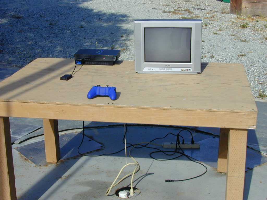
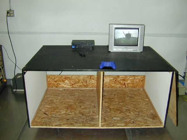
0337GDIdongle_subc Page 1 of 28 Atlas Compliance & Engineering, Inc. 1792 Little Orchard St. San Jose, CA 95125 Phone 408.971.9743 Fax 831.761.3223 .......... Atlas Compliance & Engineering, Inc. FCC Test Report FCC CFR 47 Part 15.207, 15.209, and 15.249 COMPLIANCE Go Direct International Ltd. 15 Emerson Road Milford, New Hampshire, 03055 USA Product: PS2 RF Controller Base Model: RadioWave Receiver Test Report Number:0337GDIdongle_subc Date of Report:August 29, 2003 This report contains 28 pages and may be reproduced in full only. Partial reproduction may only be done with the written consent of Atlas Compliance & Engineering, Inc. 0337GDIdongle_subc Page 2 of 28 Atlas Compliance & Engineering, Inc. 1792 Little Orchard St. San Jose, CA 95125 Phone 408.971.9743 Fax 831.761.3223 Table of Contents Table of Contents ...................................................................................................................................................2 General Information ...............................................................................................................................................3 Test Equipment.......................................................................................................................................................4 Test Configuration..................................................................................................................................................5 EUT Description / Note:.....................................................................................................................................5 EUT Support Program ........................................................................................................................................5 EUT Modifications for Compliance ...................................................................................................................5 EUT Support Devices.........................................................................................................................................6 I/O Ports and Cables ...........................................................................................................................................6 Equipment Under Test............................................................................................................................................7 Equipment Block Diagram ...................................................................................................................................13 Test Setup (Radiated Emissions) ..........................................................................................................................14 Test Setup (Conducted Emissions).......................................................................................................................18 Test Methods for Emissions .............................................................................................................................20 Conducted Emission Testing ............................................................................................................................20 Temperature and Humidity...............................................................................................................................21 Sample Calculations .........................................................................................................................................21 FCC Part 15 Subpart C 15.207 and 15.209 Limits ...............................................................................................22 Report of Measurements 15.249 Radiated Data ...............................................................................................24 Report of Measurements 15.209 Radiated Data ...............................................................................................25 Conducted Data for FCC Class B Line.............................................................................................................26 Conducted Data for FCC Class B Neutral ........................................................................................................27 COMPLIANCE VERIFICATION REPORT .......................................................................................................28 Table 1 - Support Equipment Used For Test ..........................................................................................................6 Table 2 - EUT Port Termination’s..........................................................................................................................6 Table 3 - Host Port Termination's...........................................................................................................................6 Table 4 - Radiated Emission Limits, General Requirements................................................................................22 Table 5 - Radiated Emission Limits, Operation within the bands 902 – 928 MHz, 2400 – 2483.5 MHz, 5725 – 5875 MHz, and 24.0 – 24.25 GHz................................................................................................................23 Table 6 - Conducted Limits ..................................................................................................................................23 Table 7 - Radiated Emission Level.......................................................................................................................24 Table 8 - Radiated Emission Level Below 30 MHz .............................................................................................25 Table 9 - Radiated Emission Level Below 1000 MHz .........................................................................................25 Table 11 - Line Scan Data ....................................................................................................................................26 Table 12 - Neutra…
Text truncated - open the document above for the full version.
Test Report
0337GDIdongle_subc Page 1 of 28 Atlas Compliance & Engineering, Inc. 1792 Little Orchard St. San Jose, CA 95125 Phone 408.971.9743 Fax 831.761.3223 .......... Atlas Compliance & Engineering, Inc. FCC Test Report FCC CFR 47 Part 15.207, 15.209, and 15.249 COMPLIANCE Go Direct International Ltd. 15 Emerson Road Milford, New Hampshire, 03055 USA Product: PS2 RF Controller Base Model: RadioWave Receiver Test Report Number:0337GDIdongle_subc Date of Report:August 29, 2003 This report contains 28 pages and may be reproduced in full only. Partial reproduction may only be done with the written consent of Atlas Compliance & Engineering, Inc. 0337GDIdongle_subc Page 2 of 28 Atlas Compliance & Engineering, Inc. 1792 Little Orchard St. San Jose, CA 95125 Phone 408.971.9743 Fax 831.761.3223 Table of Contents Table of Contents ...................................................................................................................................................2 General Information ...............................................................................................................................................3 Test Equipment.......................................................................................................................................................4 Test Configuration..................................................................................................................................................5 EUT Description / Note:.....................................................................................................................................5 EUT Support Program ........................................................................................................................................5 EUT Modifications for Compliance ...................................................................................................................5 EUT Support Devices.........................................................................................................................................6 I/O Ports and Cables ...........................................................................................................................................6 Equipment Under Test............................................................................................................................................7 Equipment Block Diagram ...................................................................................................................................13 Test Setup (Radiated Emissions) ..........................................................................................................................14 Test Setup (Conducted Emissions).......................................................................................................................18 Test Methods for Emissions .............................................................................................................................20 Conducted Emission Testing ............................................................................................................................20 Temperature and Humidity...............................................................................................................................21 Sample Calculations .........................................................................................................................................21 FCC Part 15 Subpart C 15.207 and 15.209 Limits ...............................................................................................22 Report of Measurements 15.249 Radiated Data ...............................................................................................24 Report of Measurements 15.209 Radiated Data ...............................................................................................25 Conducted Data for FCC Class B Line.............................................................................................................26 Conducted Data for FCC Class B Neutral ........................................................................................................27 COMPLIANCE VERIFICATION REPORT .......................................................................................................28 Table 1 - Support Equipment Used For Test ..........................................................................................................6 Table 2 - EUT Port Termination’s..........................................................................................................................6 Table 3 - Host Port Termination's...........................................................................................................................6 Table 4 - Radiated Emission Limits, General Requirements................................................................................22 Table 5 - Radiated Emission Limits, Operation within the bands 902 – 928 MHz, 2400 – 2483.5 MHz, 5725 – 5875 MHz, and 24.0 – 24.25 GHz................................................................................................................23 Table 6 - Conducted Limits ..................................................................................................................................23 Table 7 - Radiated Emission Level.......................................................................................................................24 Table 8 - Radiated Emission Level Below 30 MHz .............................................................................................25 Table 9 - Radiated Emission Level Below 1000 MHz .........................................................................................25 Table 11 - Line Scan Data ....................................................................................................................................26 Table 12 - Neutra…
Text truncated - open the document above for the full version.
Test Report
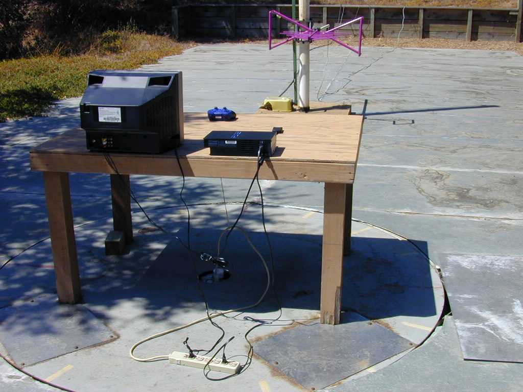
Atlas Compliance & Engineering, Inc. 1792 Little Orchard St. San Jose, CA 95125 Phone 408.971.9743 Fax 831.761.3223 OATS Data 30 Aug 2003 14:51 Atlas Compliance & Engineering, Inc. Radiated Emissions Radio Wave Dongle #3 Go-Direct Continuously Running Mario Sr. FCC Class B at 3 Meters BILOG CBL6141B with CPA9213A preamp and Semflex cable 70 F 40 %RH Test Note: Bandedge X-position 890MHz 930MHz 50kHz 120kHzPK 20msecAuto 60dB Final Measurement: X = QP @ 2sec QPQPQP HorzFreq.LevelLimitMarginAzimuth, Height 894.621.90 46.00-24.10120, 1.2M 895.2528.95 46.00-17.05120, 1.2M 895.530.24 46.00-15.76120, 1.2M 902.0525.43 46.00-20.57120, 1.2M 908.6588.61 *94.00-5.39120, 1.2M 928.0519.27 46.00-26.73120, 1.2M
Test Report
Atlas Compliance & Engineering, Inc. 1792 Little Orchard St. San Jose, CA 95125 Phone 408.971.9743 Fax 831.761.3223 OATS Data 01 Sep 2003 10:49 Atlas Compliance & Engineering, Inc. Radiated Emissions RadioWave Dongle #3 Go Direct Continuously Running Mario Sr. CISPR 22 Class B at 3 Meters BILOG CBL6141B with CPA9213A preamp and Semflex cable 70 F 40 %RH Test Note: Bandedge X position 890MHz 930MHz 50kHz 120kHzPK 20msecAuto 60dB Final Measurement: X = QP @ 2sec QPQPQP VertFreq.LevelLimitMarginAzimuth, Height 894.420.38 46.00-25.62130, 1.2M 895.827.94 46.00-18.06130, 1.2M 902.033.69 46.00-12.31130, 1.2M 908.6886.73*94.00-7.27130, 1.2M 928.0519.15 46.00-26.85130, 1.2M
Contact Information
Applicant
Polly Wong
Technical Contact
Atlas Compliance & Engineering, Inc.Bruce Smith
[email protected]831-761-2223
142 North Milpitas Blvd. · Milpitas, California · United States
Non-Technical Contact
Atlas Compliance & Engineering, Inc.Bruce Smith
[email protected]831-761-2223
Test Firm
Atlas Compliance & Engineering, Inc.Bruce Smith
Technical Specifications
| # | Rule Parts | Frequency Range | Power Output |
|---|---|---|---|
| 1 | 15C | 908.65 MHz - 915.95 MHz | - |
Other Applications from Go Direct International, Ltd.
REJGDC
Sep 28, 2003908.65 to 915.95 MHz Joypad/Transceiver
Equipment Class
DXT - Part 15 Low Power Transceiver, Rx Verified