RFIMD1Telescope Dome Control System
Diffraction Limited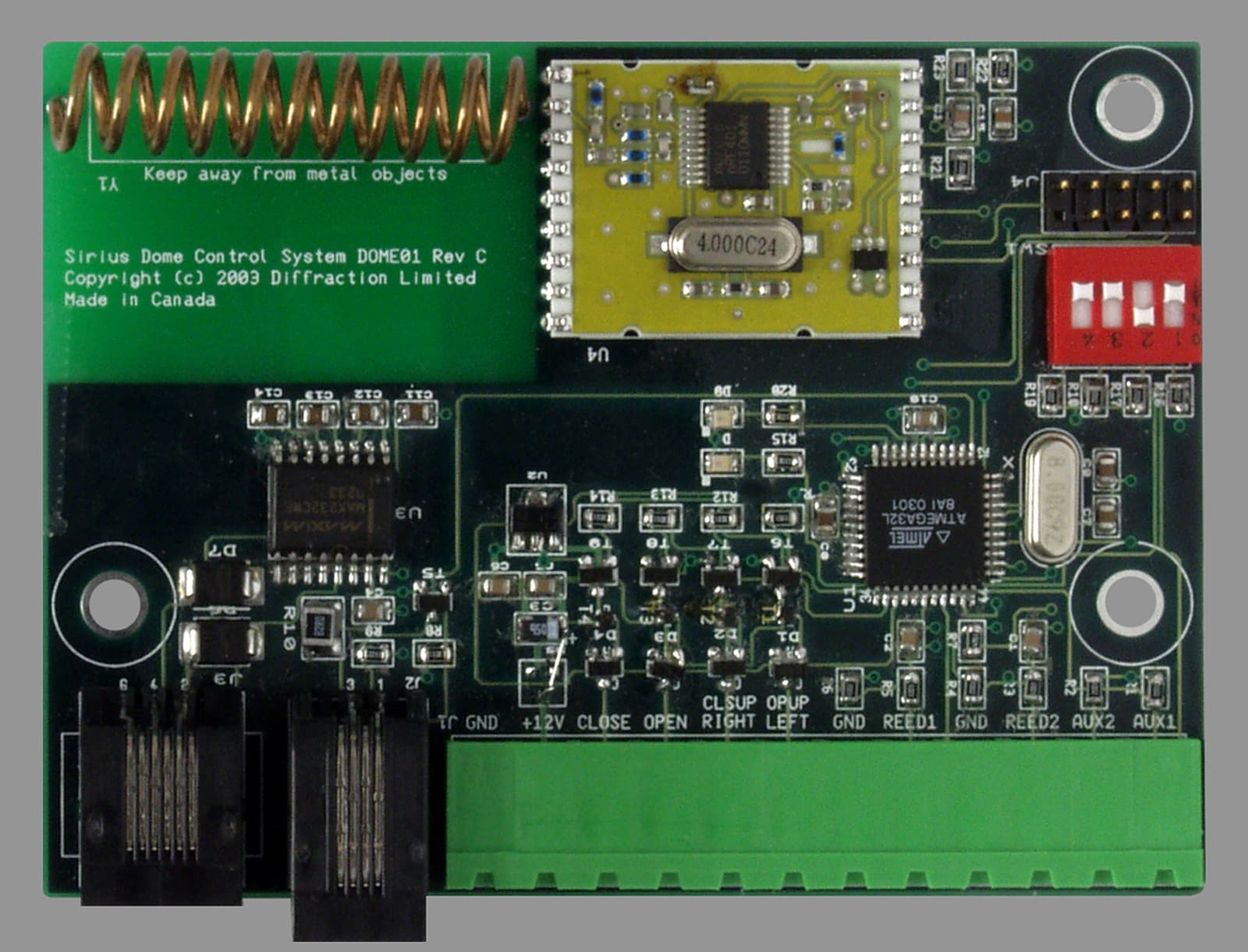
Click to zoom
Application Details
- Equipment Class
- DSR - Part 15 Remote Control/Security Device Transceiver
- Date of Grant
- Sep 25, 2003
- Application Purpose
- Original Equipment
- Date of Application
- Sep 25, 2003
- Equipment Note
- Telescope Dome Control System
- Frequency Range
- 433.93000000 - 434.33000000
- Company
- Diffraction Limited
- Country
- Canada
Documents & Files
Document Text
Text extracted from the exhibit documents filed with the FCC. Open a document above to read the original.
Users Manual
MaxDome i Table Of Contents Introduction ...........................................................................................................1 Rotation .............................................................................................................1 Shutter...............................................................................................................1 Safety....................................................................................................................3 WARNING .........................................................................................................3 Regulatory Notices................................................................................................5 FCC Notice........................................................................................................5 Caution ..............................................................................................................5 Hardware Installation ............................................................................................7 Getting Started ..................................................................................................7 Rotation Controller Installation ..........................................................................8 Controller Board.............................................................................................8 Optical Motor Sensor .....................................................................................9 Wiring...........................................................................................................11 Motor Control Wiring ....................................................................................12 Magnetic Home Sensor Wiring ....................................................................12 Power Supply Wiring....................................................................................13 DIP Switch ...................................................................................................13 Shutter Controller Installation ..........................................................................14 Controller Board...........................................................................................14 Wiring...........................................................................................................15 Motor Control Wiring ....................................................................................16 Magnetic Closed Sensor Wiring...................................................................16 Power Supply Wiring....................................................................................17 DIP Switch ...................................................................................................17 Software Installation............................................................................................19 ASCOM Platform.............................................................................................19 MaxDome Driver .............................................................................................20 Software Operation .............................................................................................21 Dome Setup ....................................................................................................21 Slaving Setup ..................................................................................................24 Normal Operation ............................................................................................26 Connecting...................................................................................................26 Opening the Shutter.....................................................................................26 Find Home ...................................................................................................26 Manual Go To ..............................................................................................27 Slaving to Telescope....................................................................................27 Shutting Down .............................................................................................27 Troubleshooting ..................................................................................................29 Computer Link Not Established .......................................................................29 Home Position Not Detected ...........................................................................29 Motor Shaft Detector Not Working...................................................................29 Open/Close Not Working.................................................................................29 Dome Rotates the Wrong Way........................................................................30 Table Of Contents ii Shutter Moves Incorrectly................................................................................30 Index ...................................................................................................................31 1 Introduction The MaxDome controller system provides complete automated control of a telescope dome and associated shutter. For lower-cost installations, rotation-only operation is also supported. The MaxDome controller system is available in two configurations: rotation only, and rotation plus shutter control. Rotation The Controller Card connects directly to a Windows-based Personal Computer via an RS-232 link. The MaxDome driver in the computer handles all communications to the controller board. The controller card directly controls a motor driver board, which turns on the motor in either the forward or backwards direction. The Motor Sensor counts rotations of the motor shaft; this is used to detect when the dome has rotated to the correct position. One side of the shaft is colored black, the other is …
Text truncated - open the document above for the full version.
Cover Letter(s)
Attn: Reviewing Engineer Federal Communications Commission 7435 Oakland Mills Road Columbia, MD 21046 RE: CONFIDENTIALITY REQUEST FOR MODEL MD-1 , FCC ID: RFIMD1 To Whom It May Concern: This letter serves as an official request for confidentiality under FCC Rule Section 0.459. We have requested that the schematic diagrams, parts list and block diagram required to be submitted with this application be withheld from public review. These documents are company proprietary information, which we do not want to have available to our competition. Please contact me if there is any information you may need. Sincerely, Diffraction Limited Douglas B. George President 100 Craig Henry Drive, Unit 106 Ottawa, Ontario Canada, K2G 5W3 Phone: (613) 225-2732 Fax: (613) 225-9688 www.diffractionlimited.com
Cover Letter(s)
Response to TCB Findings 1. There are 2 frequencies listed on Form 731 and the report, but the test results only address 433.93MHz. Please clarify. Response: See attached TCB Replies for 3W06960 2. Please provide a more detailed plot to determine the 10 seconds minimum silent period between transmissions. The plot shows roughly 10 seconds and the user manual states exactly 10 seconds on the last paragraph of page 2. Response: See attached TCB Replies for 3W06960 3. On page 13 of the manual alternative power source is mentioned. Has the testing been conducted with a 12VDC battery or power supply? If the device has the capability to connect to a DC power supply, compliance to 15.207 and 15.31(e) should be demonstrated. Please clarify. Response: See attached TCB Replies for 3W06960 4. Please specify the label material. Response: The label material is mylar 5. The user's manual should include 15.105(b) statements as the device can connect to a PC. Please supply a revised manual. Response: See revised manual
ID Label/Location Info
DIFFRACTION LIMITED Model No.: MD-1 IC: 4715A-MD1 FCC ID: RFIMD1 * This device complies with Part 15 of the FCC Rules. Operation is subject to the following two conditions: (1) This device may not cause harmful interference, and (2) This device must accept any interference received, including interference that may cause undesired operation. Made in Canada Dimensions: ¾” High by 2.5” Wide
ID Label/Location Info
D IF F R A C T IO NL IM IT E DM o d e lN o . :M D - 1 IC :4715A-M D1FC CID:R F IM D1 *T hisdeviceco mp lieswi thP art1 5o ftheF CCRules.O perationis sub j ecttothefo llo wi n gt woc o nd itio ns:( 1 )T hisd evicem a yno tc a use har mfuli nter ference,a nd(2)T hisdevicemustaccepta nyinter ference received,incl ud inginter ferenc ethatma yca useund esiredoperation. MadeinCanada (Bottomsideofprintedcircuitboard)
Operational Description
Operational Description The MD-1 is designed to control an astronomical telescope dome. It is a simple device comprised of a microcontroller, a 433 MHz transceiver module, integrated helical antenna, and I/O devices to connect with external DC motor control relays, an optical sensor, and two magnetic switches. The MD-1 operates from the dome's 12VDC power supply (lead-acid battery with solar cell charger). The MD-1 units are used in pairs; one driving the dome rotation, and one riding on the dome controlling the shutters (open/close). A 433 MHz RF link provides the communications between the two units. The microcontroller in the MD-1 continuously monitors the telescope dome slit position via the optical sensor and magnetic home sensor. It receives updates on the telescope position and user input from a PC. When required, it can rotate the dome by actuating a DC motor. The "base" MD-1 periodically sends an RF message to the "shutter" board. This message can be a simple poll, or can include a command to open or close the shutter. The "shutter" MD-1 responds back with the current shutter state (open/closed/moving/error).
Test Report
Master:PT15-Sub-C-15231 Date: November 12, 2001 Test Report: 3W06960 Applicant: Diffraction Ltd. 106-100 Craig Henry Dr. Ottawa, K2G 5W3 Equipment Under Test: Max Dome (EUT) In Accordance With: FCC Part 15, Subpart C, 15.231 Tested By: Nemko Canada Inc. 303 River Road, R.R. 5 Ottawa, Ontario K1V 1H2 Authorized By: Glen Westwell, Wireless Technologist Date: 29 August 2003 Total Number of Pages: 15 Nemko Canada Inc. FCC PART 15, SUBPART C, 15.231 PROJECT NO.:3W06960 EQUIPMENT: Max Dome Page 2 of 14 Table of Contents Section 1. Summary of Test Results ...................................................................................3 Section 2. Equipment Under Test .......................................................................................5 Section 3. Transmission Requirements ..............................................................................6 Section 4. Occupied Bandwidth ..........................................................................................9 Section 5. Periodic Alternate Field Strength Requirements ..........................................11 Section 6. Block Diagrams .................................................................................................14 Section 7. Test Equipment List ..........................................................................................15 Nemko Canada Inc. FCC PART 15, SUBPART C, 15.231 PROJECT NO.:3W06960 EQUIPMENT: Max Dome Page 3 of 14 Section 1. Summary of Test Results General All measurements are traceable to national standards. These tests were conducted on a sample of the equipment for the purpose of demonstrating compliance with Part 15, Subpart C. All tests were conducted using measurement procedure ANSI C63.4-1992. Radiated emissions are made on an open area test site. A description of the test facility is on file with the FCC. THIS TEST REPORT RELATES ONLY TO THE ITEM(S) TESTED. THE FOLLOWING DEVIATIONS FROM, ADDITIONS TO, OR EXCLUSIONS FROM THE TEST SPECIFICATIONS HAVE BEEN MADE. See “ Summary of Test Data”. TESTED BY: ______________________________ DATE: 28 August 2003 Kevin Carr, EMC/EMI/Wireless Specialist Nemko Canada Inc. authorizes the above named company to reproduce this report provided it is reproduced in its entirety and for use by the company’s employees only. Any use which a third party makes of this report, or any reliance on or decisions to be made based on it, are the responsibility of such third parties. Nemko Canada Inc. accepts no responsibility for damages, if any, suffered by any third party as a result of decisions made or actions based on this report. This report applies only to the items tested. Nemko Canada Inc. FCC PART 15, SUBPART C, 15.231 PROJECT NO.:3W06960 EQUIPMENT: Max Dome Page 4 of 14 Summary Of Test Data Name of Test Para. Number Results Transmission Requirements 15.231(a) Complies Radiated Emissions 15.231(b) N/A Occupied Bandwidth 15.231(c) Complies Frequency Tolerance 15.231(d) N/A Periodic Alternate Field Strength Requirements 15.231(e) Complies Powerline Conducted Emissions 15.207 N/A Test Conditions: Indoor Temperature: 24 °C Humidity: 43 % Outdoor Temperature: 24 °C Humidity: 68 % Nemko Canada Inc. FCC PART 15, SUBPART C, 15.231 PROJECT NO.:3W06960 EQUIPMENT: Max Dome Page 5 of 15 Section 2. Equipment Under Test General Equipment Information Manufacturer: Diffraction Ltd. Model No.: MD-1 Serial No.: 1001, 1002 Date Received In Laboratory: 25 Aug 03 Nemko Identification No.: 1 & 2 OCCUPIED BANDWIDTH (99% BW): 44.0kHz TYPE OF MODULATION: FSK EMISSION DESIGNATOR (TRC-43): 44K0P0D FREQUENCY RANGE (or fixed frequency): 433.93 and 434.33 MHz Nemko Canada Inc. FCC PART 15, SUBPART C, 15.231 PROJECT NO.:3W06960 EQUIPMENT: Max Dome Page 6 of 15 Section 3. Transmission Requirements Para. No.: 15.231(a) Test Performed By: Kevin Carr Date of Test: 25 Aug. 03 Minimum Standard: 15.231(a) Continuous transmissions such as voice, video or data transmissions are not permitted. 15.231(a)(1) A manually operated transmitter shall employ a switch that will automatically deactivate the transmitter within not more than 5 seconds after being released. 15.231(a)(2) A transmitter activated automatically shall cease transmission within 5 seconds of activation. 15.231(a)(3) Periodic transmissions at regular pre-determined intervals are not permitted. However polling or supervisory transmissions to determine system integrity of transmitters used in security or safety applications are allowed if the periodic rate of transmission does not exceed one transmission of not more than one second duration per hour for each transmitter. 15.231(a)(4) Intentional radiators which are employed for radio control purposes during emergencies involving fire, security, and safety of life, when activated to signal an alarm, may operate during the pendency of the alarm. Test Results: Complies Test Data: Compliance was determined by verification of technical specifications and a functional test on the equipment. Nemko Canada Inc. FCC PART 15, SUBPART C, 15.231 PROJECT NO.:3W06960 EQUIPMENT: Max Dome Page 7 of 15 Rationale for Compliance with Transmission Requirements 15.231(a)(1) : The EUT does not Transmit continuously, See Plot 15.231(a)(2) : The Transmit on time is less then 5 seconds, See Plot 15.231(a)(3) : The EUT Polls the Receiver every 10 seconds, See Plot and Radiated Emissions, section 4 15.231(a)(4) : The EUT is not intended for control purposes during emergencies involving fire, security, and safety of life Nemko Canada Inc. FCC PART 15, SUBPART C, 15.231 PROJECT NO.:3W06960 EQUIPMENT: Max Dome Page 8 of 15 Nemko Canada Inc. FCC PART 15, SUBPART C, 15.231 PROJECT NO.:3W06960 EQUIPMENT: Max Dome Page 9 of 15 Section 4. Occupied Bandwidth Para. No.: 15.231(c) Test Performed By: Kevin Carr Date of Test: 25 Aug. 03 Minimum Standard: 15.231(c) The bandwidth of the emission shall be no wider than 0.25% of the center frequency for devices operating above 70 MHz and below 900 MHz. For dev…
Text truncated - open the document above for the full version.
Test Report
TCB Replies for 3W06960 Item 3 The EUT can transmit on either of two frequencies separated by 0.4MHz. The Eut was tested in accordance with Section 15.31(m). Please advise if this is incorrect. Item 4 Item 5 Item 5 Voltage Fieldstrength (dBuV) STV 67.7 dBuV/m 85%STV 67.7 dBuV/m 115%STV 67.7 dBuV/m STV=120VAC,60Hz
Test Setup Photos
Nemko Canada Inc. FCC PART 15, SUBPART C, 15.231 PROJECT NO.:3W06960 EQUIPMENT: Max Dome Page 13 of 15 Oats Set-up Photo’s
Contact Information
Applicant
Douglas Brooks George(President)
Test Firm
Nemko Canada Inc.Stuart Beck
Technical Specifications
| # | Rule Parts | Frequency Range | Power Output |
|---|---|---|---|
| 1 | 15.231(e) | 433.93 MHz - 434.33 MHz | - |