RFN5405RDK0401802.11a CardBus Card
RF Micro Devices, Inc.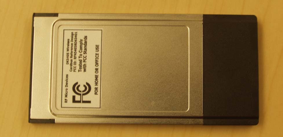
Click to zoom
Application Details
- Equipment Class
- NII - Unlicensed National Information Infrastructure TX
- Date of Grant
- Jan 08, 2004
- Application Purpose
- Original Equipment
- Date of Application
- Nov 20, 2003
- Equipment Note
- 802.11a CardBus Card
- Frequency Range
- 5180.00000000 - 5320.00000000
- Company
- RF Micro Devices, Inc.
- Country
- United States
Documents & Files
Document Text
Text extracted from the exhibit documents filed with the FCC. Open a document above to read the original.
Cover Letter(s)
File: R51561 June 17, 2003 Chief, Equipment Authorization Branch, Authorization and Evaluation Division, Office of Engineering and Technology FEDERAL COMMUNICATIONS COMMISSION P.O. Box 358315 Pittsburgh, PA 15251-5315 Gentlemen: The enclosed documents constitute a formal submittal and application for a Grant of Equipment Authorization pursuant to Subpart E of Part 15 of FCC Rules (CFR 47) regarding intentional radiators. Data within this report demonstrates that the equipment tested complies with the FCC limits for intentional radiators. Elliott Laboratories, as duly authorized agent prepared this submittal. A copy of the letter of our appointment as agent is enclosed. If there are any questions or if further information is needed, please contact Elliott Laboratories for assistance. Sincerely, Mark Briggs Director of Engineering MB/dmg Enclosures: Agent Authorization Letter Emissions Test Report with Exhibits
External Photos
External Photographs
ID Label/Location Info
DK5405 Document # RD-5405-PCCARD-SP21 IEEE 802.11A WLAN DK5405 PC Card Reference Design FCC Label Locations Document #. RD-5405-PCCARD-SP2 ii Life Support Applications RF Micro Devices products are not designed for use in life support applications or applications where malfunction can result in bodily injury. Customers use or sell RF Micro Devices products at their own risk and agree to fully indemnify RF Micro Devices for any damages resulting from improper use or sale. Application Information To obtain the most recent Application Notes and other useful information for your design application, please visit the RF Micro Devices web site at www.rfmd.com, or contact RF Micro Devices directly. Copyright Notice This document is developed as part of a technology agreement between RTX Telecom A/S, Denmark and RF Micro Devices, Inc. Unauthorized copying is not allowed. Do not reproduce, transform to any other format, or send/ transmit any part of this documentation without the express written permission of RF Micro Devices, Inc.. Trademark Acknowledgment RF Micro Devices is a trademark of RF Micro Devices, Inc. All other trademarks are the property of their respective holders. Disclaimer This document provides technical information for the user. RF Micro Devices, Inc. reserves the right to modify the information in this document as necessary and without notice. Customers should make sure that they have the most recent datasheet version. RF Micro Devices, Inc. is not responsible for any errors that may appear in this document. Customers should take appropriate action to ensure their use of the products does not infringe upon any patents. RF Micro Devices, Inc. respects valid patent rights of third parties and does not infringe upon or assist others to infringe upon such rights. Contact RF Micro Devices, Inc. 7628 Thorndike Road Greensboro, NC 27409, USA Tel (336) 664 1233 Fax (336) 664 0454 http://www.rfmd.com Document # RD-5405-PCCARD-SP2 iii RF5405 PC CARD Reference Design FCC Label Location 54 mm 7.52 mm 30.25 mm 82.3 mm 12.45 mm Document #. RD-5405-PCCARD-SP2 iv
Internal Photos
Internal Photographs Bottom of Card Top of Card (shield removed) Top of card (shield in place)
RF Exposure Info
SAR COMPLIANCE TESTING OF RF MICRO DEVICES 802.11a CARDBUS CARD MODEL DK5405 WITH TOSHIBA MODEL 1415-S173 HOST COMPUTER FCC ID# RFN5405RDK0401 Host Computer: Toshiba Model 1415-S173 S/N: 9207316P October 15, 2003 Prepared for: RF Micro Devices, Inc. 7628 Thorndike Road Greenboro, NC 27409, U.S.A. Prepared by: Om P. Gandhi Professor of Electrical and Computer Engineering University of Utah 50 S Central Campus Dr., Rm. 3280 Salt Lake City, UT 84112-9206 ii TABLE OF CONTENTS I. Introduction ..................................................................................................................... 1 II. The SAR Measurement System ...................................................................................... 2 The Flat Phantom ............................................................................................................ 2 III. Calibration of the E-Field Probe ..................................................................................... 3 IV. SAR System Verification ................................................................................................ 4 V. Tissue Simulant Fluid for the Frequency Band 5.2 to 5.8 GHz ...................................... 5 VI. The Measured SAR Distributions ................................................................................... 7 VII. Comparison of the Data with FCC 96-326 Guidelines ................................................... 9 REFERENCES ........................................................................................................................ 10 TABLES .................................................................................................................................. 12 FIGURES ................................................................................................................................. 17 APPENDIX A .......................................................................................................................... 33 APPENDIX B .......................................................................................................................... 36 APPENDIX C .......................................................................................................................... 38 APPENDIX D .......................................................................................................................... 43 APPENDIX E .......................................................................................................................... 59 APPENDIX F ........................................................................................................................... 72 APPENDIX G ........................................................................................................................... 74 APPENDIX H ........................................................................................................................... 86 1 SAR COMPLIANCE TESTING OF RF MICRO DEVICES 802.11a CARDBUS CARD MODEL DK5405 WITH TOSHIBA MODEL 1415-S173 HOST COMPUTER FCC ID# RFN5405RDK0401 Host Computer: Toshiba Model 1415-S173 S/N: 9207316P I. Introduction We have used the measurement procedures outlined in FCC Supplement C (Edition 97- 01) to OET Bulletin 65 [1] and an updated version of the same [2] for evaluating compliance of the RF Micro Devices Cardbus Card Model DK5405 (FCC ID# RFN5405RDK0401) inserted into Toshiba Model 1415-S173 Host Computer. Three photographs of the Toshiba Model 1415- S173 Host Computer with RF Micro Devices Cardbus Card Model DK5405 are given in Figs. 1a-c respectively. The RF Micro Devices Cardbus Card Model DK5405 uses two identical antennas that operate over the frequency band 5.18 to 5.32 GHz in the normal mode with conducted powers that are given in Table 1. For SAR measurements, two configurations of the wireless PC relative to the experimental phantom have been used. These are as follows: a. Configuration 1 is for the wireless PC placed on a user's lap. For this configuration, a planar phantom model with inside dimensions 12" × 16.5" (30.5 × 41.9 cm) and a base thickness of 2.0 ± 0.2 mm (recommended in [2]) was used for SAR measurements and the bottom side of the laptop computer shown in Fig. 1 was pressed against it (see Fig. 2). b. Configuration 2 – Edge-on position. This configuration corresponds to a bystandar close to the outer edge of the Cardbus Card. For this configuration, the PC is placed at 90º with the edge of the RF Micro Devices Model DK5405 Cardbus Card pressed against the bottom of the planar phantom. A photograph for this edge-on position for SAR testing is given in Fig. 3. 2 II. The SAR Measurement System The University of Utah SAR Measurement System has been described in peer-reviewed literature [3]. A photograph of the SAR Measurement System is given in Fig. 4. This SAR Measurement System uses a computer-controlled 3-D stepper motor system (Arrick Robotics MD-2A). A triaxial Narda Model 8021 E-field probe is used to determine the internal electric fields. The positioning repeatability of the stepper motor system moving the E-field probe is within ± 0.1 mm. Outputs from the three channels of the E-field probe are dc voltages, the sum of which is proportional to the square of the internal electric fields ( ) 2 i E from which the SAR can be obtained from the equation SAR = ( ) 2 i Eσρ, where σ and ρ are the conductivity and mass density of the tissue-simulant materials, respectively [4]. The dc voltages for the three channels of the E-field probe are read by three HP 34401A multimeters and sent to the computer via an HPIB interface. The setup is carefully grounded and shielded to reduce the noise due to the electromagnetic interference (EMI). A cutout in a wooden table allows placement of a plastic holder (shown in Fig. 5) on which the laptop computer with the 802.11a wireless antennas (see Fig. 1) is supported. The plastic holder (see Fig. 5) can be moved up or down so …
Text truncated - open the document above for the full version.
Test Report
File: R51561 Page 1 of 16 Electromagnetic Emissions Test Report and Application for Grant of Equipment Authorization pursuant to FCC Part 15, Subpart E (UNII Devices) and Industry Canada RSS 210 Issue 5 (LELEAN Devices) on the RF Micro Devices Model: RD5400 FCC ID: RFN5405RDK0401 GRANTEE: RF Micro Devices 7628 Thorndike Road Greensboro, NC 27409 TEST SITE: Elliott Laboratories, Inc. 684 W. Maude Avenue Sunnyvale, CA 94086 REPORT DATE: June 17, 2003 FINAL TEST DATE: June 6, 2003 AUTHORIZED SIGNATORY: ______________________________ Mark Briggs Director of Engineering Elliott Laboratories, Inc. is accredited by the A2LA, certificate number 2016-01, to perform the test(s) listed in this report. This report shall not be reproduced, except in its entirety, without the written approval of Elliott Laboratories, Inc. Elliott Laboratories, Inc. -- EMC Department Test Report Report Date: June 17, 2003 File: R51561 Page 2 of 16 pages TABLE OF CONTENTS COVER PAGE..................................................................................................................................................................................1 TABLE OF CONTENTS...............................................................................................................................................................2 SCOPE.............................................................................................................................................................................................3 OBJECTIVE...................................................................................................................................................................................3 SUMMARY OF RESULTS...........................................................................................................................................................4 MEASUREMENT UNCERTAINTIES....................................................................................................................................5 EQUIPMENT UNDER TEST (EUT) DETAILS..........................................................................................................................6 GENERAL...................................................................................................................................................................................6 ENCLOSURE..............................................................................................................................................................................6 MODIFICATIONS....................................................................................................................................................................6 SUPPORT EQUIPMENT..........................................................................................................................................................6 EUT INTERFACE PORTS........................................................................................................................................................6 EUT OPERATION DURING TESTING..................................................................................................................................7 ANTENNA REQUIREMENTS................................................................................................................................................7 TEST SITE......................................................................................................................................................................................8 GENERAL INFORMATION....................................................................................................................................................8 CONDUCTED EMISSIONS CONSIDERATIONS................................................................................................................8 RADIATED EMISSIONS CONSIDERATIONS....................................................................................................................8 MEASUREMENT INSTRUMENTATION..................................................................................................................................9 RECEIVER SYSTEM.................................................................................................................................................................9 INSTRUMENT CONTROL COMPUTER..............................................................................................................................9 LINE IMPEDANCE STABILIZATION NETWORK (LISN)...............................................................................................9 POWER METER......................................................................................................................................................................10 FILTERS/ATTENUATORS...................................................................................................................................................10 ANTENNAS............................................................................................................................................................................10 ANTENNA MAST AND EQUIPMENT TURNTABLE....................................................................................................10 INSTRUMENT CALIBRATION...........................................................................................................................................10 TEST PROCEDURES.................................................................................................................................................................11 EUT AND CABLE PLACEMENT.........................................................................................................................................11 CONDUCTED EMISSIONS.......................................................................................…
Text truncated - open the document above for the full version.
Test Setup Photos
Radiated Emissions Test Configuration Photographs Radiated Emissions Test Configuration Photographs Conducted Emissions Test Configuration Photographs Conducted Emissions Test Configuration Photographs
Contact Information
Applicant
William D Simmons(Applications Engineer)
Technical Contact
Elliott LaboratoriesMark R Briggs
[email protected]408-245-7800
684 West Maude Ave · Sunnyvale, California · United States
Non-Technical Contact
Elliott LaboratoriesMark R Briggs
[email protected]408-245-7800
Test Firm
Elliott Laboratories LLCDavid Bare
Technical Specifications
| # | Rule Parts | Frequency Range | Power Output | Tolerance |
|---|---|---|---|---|
| 1 | 15E | 5.18 GHz - 5.32 GHz | 45.00 mW | 10.0000000000 ppm |