RFW418LFITLocating Transmitter
Goggin Research & Engineering, PC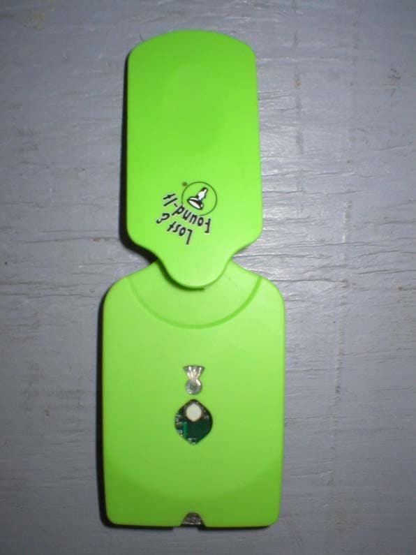
Click to zoom
Application Details
- Equipment Class
- DSC - Part 15 Security/Remote Control Transmitter
- Date of Grant
- Sep 11, 2003
- Application Purpose
- Original Equipment
- Date of Application
- Sep 11, 2003
- Equipment Note
- Locating Transmitter
- Frequency Range
- 418.00000000 - 418.00000000
- Country
- United States
Documents & Files
Document Text
Text extracted from the exhibit documents filed with the FCC. Open a document above to read the original.
Users Manual
26 August 2003 Goggin Research & Engineering, PC 4510-D Northchase Parkway, NE Wilmington, North Carolina 28405-7485 Phone: 910-799-6202 Fax: 910-799-6801 User Manual for 418LFIT FCC ID RFW418LFIT This device complies with Part 15 of the FCC Rules. Operation is subject to the following two conditions: (1) this device may not cause harmful interference, and (2) this device must accept any interference received, including interference that may cause undesired operation. For the 418LFIT : - This is a component system that consists of MSP430TX transmitter and one or more of the RXPOT430B receivers. Attach the receivers to various objects. Using the transmitter as instructed below search out the receivers when needed. For the MSP430TX : - Press the button to start the transmitter. It will shut off automatically in 5 seconds. - While it is operating, a light just above the button flashes for each transmission, about once a second. - An additional light is at the bottom of the unit. It will stay lighted during the entire time the unit is in operation. Except for low battery conditions, it will blink instead of being continuous. This means that the batteries are low and need replacement. - To replace the batteries, remove the Phillips screw on the bottom side of the unit. Lift the battery cover away from the unit. Replace the CR2032 batteries one at a time. Replace the cover and reinstall the screw. For the RXPOT430B : - The unit will alternate flashing and buzzing when being searched for by the MSP430TX for up to 40 feet away. It will do this for 3 second intervals until the transmitter is turned off. NOTE : This equipment has been tested and found to comply with the limits for a Class B digital device, pursuant to Part 15 of the FCC Rules. These limits are designed to provide reasonable protection against harmful interference in a residential installation. This equipment generates, uses and can radiate radio frequency energy and, if not installed and used in accordance with the instructions, may cause harmful interference to radio communications. However, there is no guarantee that interference will not occur in a particular installation. If this equipment does cause harmful interference to radio or television reception, which can be determined by turning the equipment off and on, the user is encouraged to try to correct the interference by one or more of the following measures: -- Reorient or relocate the receiving antenna. -- Increase the separation between the equipment and receiver. -- Connect the equipment into an outlet on a circuit different from that to which the receiver is connected. -- Consult the dealer or an experienced radio/TV technician for help. Warning: FCC Regulations state that any unauthorized changes or modifications to this equipment not expressly approved by the manufacturer could void the user's authorization to operate this equipment.
Cover Letter(s)
Response to TCB Findings Please specify the worst case transmission duration observed. The 5-second maximum transmission is controlled by programming of the control chip. We measured the transmission duration, which indicated a maximum "on" time of 4.85 seconds. Please supply a signed copy of the confidentiality request. Supplied.
Test Report
RF Emissions Test Report To Determine Compliance With: FCC, Part 15 Rules and Regulations Model number: MSP 430 August 25, 2003 Manufacturer: Goggin Research & Engineering, PC 4510-D Northchase Parkway NE Wilmington, North Carolina 28405 EMC Testing Laboratories, Inc. authorizes the above company to reproduce this report provided it is reproduced in its entirety EMC Testing Lab. (770) 475-8819 Test report no. 03-173A Page 2 of 1 1 8 8 Contents Section General Information ....................................................................... 1 Test Summary.................................................................................. 2 Standard Reference ........................................................................ 3 Test Method ......................................................................... 4 Radiated Out of Band Emissions Measurements ........................... 5 Fundamental Frequency Radiated Emissions Measurements ........ 6 Occupied Bandwidth Measurements .............................................. 7 EMC Testing Lab. (770) 475-8819 Test report no. 03-173A Page 3 of 1 1 8 8 Section 1 General Information Manufacturer: Goggin Research & Engineering 4510-D Northchase Parkway NE Wilmington, North Carolina 28405 Manufacturer representative: Mr. Chris Goggin Equipment covered by this report: Model no.: MSP 430 Options covered by this report: None Equipment serial no. Prototype Test specifications: To determine compliance with: FCC, Part 15.231, Subpart C Rules and Regulations, Class B Test report number: 03-173A Test commenced: August 19, 2003 Test completed: August 22, 2003 Test engineer: Edward Barnes Test Facility: The test facility used to perform these tests is on file with the FCC under registration number 637500 and located at: EMC Testing Laboratories, Inc. 2210 Justin Trail Alpharetta, GA 30004 EMC Testing Lab. (770) 475-8819 Test report no. 03-173A Page 4 of 1 1 8 8 Section 2 Test report summary sheet 1 of 2 Summary: Tests Results FCC, Part 15, Class B, Radiated emissions: Pass FCC, Part 15, Class B, Conducted emissions: N/A 1- The product(s) covered by this report was found to comply with the limits indicated in paragraphs 15.109 Subpart B and 15.231, Part 15, Subpart C of the FCC Rules and Regulations. Note: The conducted emissions test was not performed since the EUT is battery operated with no means for connection to public mains. Product description: The product(s) covered by this report consisted of a battery-operated transmitter, intended for use with an associated receiver to tag and find articles. The transmitter is an intentional radiator operating at 418MHz and transmits when a manual switch is depressed. The transmitter stops transmission within 5 seconds of operation. The transmitter was set to its maximum duty cycle of 8.5% The enclosure is constructed of plastic with overall dimensions measuring 15.5cm long by 5.5cm wide by 1.7cm high and encloses the following components judged as critical: 1. A transmitter board, part no. MSP430TX. 2. Two new, fully charged 3V lithium Ion batteries. EMC Testing Lab. (770) 475-8819 Test report no. 03-173A Page 5 of 1 1 8 8 Test report summary sheet 2 of 2 Test configuration: The equipment under test was set-up and configured as specified by the manufacturer. 1- The EUT was connected to the following support peripherals. A) None 2- The EUT was connected to the following cables. A) None Test operation: For all measurements, the equipment under test was and caused to function in a continuous mode of operation for maximum electrical activity as specified by the manufacturer. Specifically, the EUT was caused to continually transmit, utilizing its maximum 8.5% duty cycle while been powered from fresh batteries. Modifications: The following modifications were required to comply with the indicated limits: 1- The value of resistor R5 was changed from 47 ohm to 100 ohm to reduce the output power of the fundamental and second harmonic. Conclusion: With the above indicated modifications, the product(s) covered by this report has been tested and found to comply with the limits indicated in paragraph 15.231 table (b) of the FCC, Part 15, Subpart C Rules and Regulations and all subsequent limits indicated therein for a class B device. Tested by: Reviewed by: Edward Barnes Gene J. Bailey RF Engineer Engineering Manager EMC Testing Laboratories, Inc. EMC Testing Laboratories, Inc. August 25, 2003 August 25, 2003 EMC Testing Lab. (770) 475-8819 Test report no. 03-173A Page 6 of 1 1 8 8 Section 2 cont... This page intentionally left blank. (Reserved for future use) EMC Testing Lab. (770) 475-8819 Test report no. 03-173A Page 7 of 1 1 8 8 Section 3 STANDARD REFERENCE The following primary standards were used for this test: 1) ANSI C63.4-2001: Method of Measurements of Radio-Noise Emissions from Low- Voltage Electrical and Electronic Equipment in the 9 Khz to 40 Ghz. 2) US Code of Federal Regulations (CFR) 1998: Title 47, Part 15, Radio Frequency Devices, Subpart C, Intentional Radiators. EMC Testing Lab. (770) 475-8819 Test report no. 03-173A Page 8 of 1 1 8 8 Section 4 TEST METHOD INTRODUCTION: The product(s) covered by this report were subjected to electromagnetic interference emissions measurements to determine compliance with the FCC, Part 15 requirements. Radiated emissions were measured in accordance with Methods of Measurement of Radio-Noise Emissions from Low-Voltage Electrical and Electronic Equipment in the Range of 9 Khz to 40 Ghz, C63.4. MEASUREMENT CALCULATIONS: Radiated Emissions : For radiated emissions measurements, the signal attenuation due to impedance losses in the antenna and signal cable was significant and was added to the spectrum analyzer reading to give corrected signal strength reading. Additionally, a 6dB attenuator was utilized at the antenna to prevent over driving the front end of the preamplifier and was added to the spectrum analyzer reading. If a preamplifier was used, the signal gain was …
Text truncated - open the document above for the full version.
Contact Information
Applicant
Chris Goggins(President)
Test Firm
EMC Testing Laboratories, Inc.Gene Bailey
Technical Specifications
| # | Rule Parts | Frequency Range | Power Output |
|---|---|---|---|
| 1 | 15.231 | 418 MHz - 418 MHz | - |