RIAHCPLUS3180-THousecall Plus Transmitter
St. Jude Medical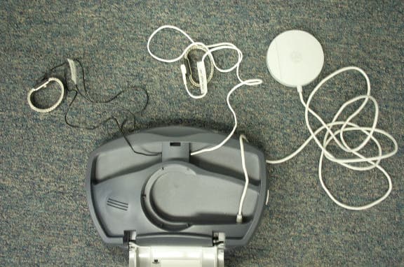
Click to zoom
Application Details
- Equipment Class
- DCD - Part 15 Low Power Transmitter Below 1705 kHz
- Date of Grant
- Oct 02, 2003
- Application Purpose
- Original Equipment
- Date of Application
- Oct 02, 2003
- Equipment Note
- Housecall Plus Transmitter
- Frequency Range
- 0.06400000 - 0.06400000
- Company
- St. Jude Medical
- Country
- United States
Documents & Files
Document Text
Text extracted from the exhibit documents filed with the FCC. Open a document above to read the original.
Users Manual
USER'S MANUAL ECG 650 USER’S MANUAL IS-1 E= V 2 R .t Housecall Plus ™ Remote Follow-Up System Transmitter Model 3180-T HC+Trans(US).book Page 1 Wednesday, August 27, 2003 2:00 PM HC+Trans(US).book Page 2 Wednesday, August 27, 2003 2:00 PM CAUTION Federal (USA) law restricts this device to sale by or on order of a physician. Housecall Plus ™ Remote Follow-Up System Transmitter Model 3180-T User’s Manual © 2003 St. Jude Medical Cardiac Rhythm Management Division All rights reserved. HC+Trans(US).book Page 3 Wednesday, August 27, 2003 2:00 PM ® or ™ indicates that the name is a trademark of, or licensed to, St. Jude Medical, Inc. or one of its subsidiaries. HC+Trans(US).book Page 4 Wednesday, August 27, 2003 2:00 PM Table of Contentsi TABLE OF CONTENTS INTRODUCTION . . . . . . . . . . . . . . . . . . . . . . . . . . . . . . . . . . . . . . . . . . . 1 What is the Housecall Plus™ System? . . . . . . . . . . . . . . . . . . . . . . . . . . . . . 1 What Does the Housecall Plus™ Transmitter Do? . . . . . . . . . . . . . . . . . . . . 2 How Does the Transmitter Affect Your Telephone? . . . . . . . . . . . . . . . . . . 2 Can You Use the Transmitter While Traveling? . . . . . . . . . . . . . . . . . . . . . . 3 IMPORTANT SAFEGUARDS . . . . . . . . . . . . . . . . . . . . . . . . . . . . . . . . . . . . 3 S ETTING UP THE TRANSMITTER . . . . . . . . . . . . . . . . . . . . . . . . . . . . . . . . 4 T HE HOUSECALL PLUS™ REMOTE FOLLOW-UP SESSION . . . . . . . . . . . . . . 7 Before You Start the Session . . . . . . . . . . . . . . . . . . . . . . . . . . . . . . . . . . . . 7 Using the Transmitter . . . . . . . . . . . . . . . . . . . . . . . . . . . . . . . . . . . . . . . . . . 8 TROUBLESHOOTING . . . . . . . . . . . . . . . . . . . . . . . . . . . . . . . . . . . . . . . 11 C ARING FOR THE TRANSMITTER . . . . . . . . . . . . . . . . . . . . . . . . . . . . . . . 12 G LOSSARY . . . . . . . . . . . . . . . . . . . . . . . . . . . . . . . . . . . . . . . . . . . . . . 12 T ECHNICAL SUPPORT . . . . . . . . . . . . . . . . . . . . . . . . . . . . . . . . . . . . . . 13 FCC I NFORMATION . . . . . . . . . . . . . . . . . . . . . . . . . . . . . . . . . . . . . . . 13 W ARRANTY . . . . . . . . . . . . . . . . . . . . . . . . . . . . . . . . . . . . . . . . . . . . . 15 A DDITIONAL TECHNICAL INFORMATION . . . . . . . . . . . . . . . . . . . . . . . . . 16 Electrical Rating . . . . . . . . . . . . . . . . . . . . . . . . . . . . . . . . . . . . . . . . . . . . . . 16 Storage Conditions . . . . . . . . . . . . . . . . . . . . . . . . . . . . . . . . . . . . . . . . . . . 16 Symbols . . . . . . . . . . . . . . . . . . . . . . . . . . . . . . . . . . . . . . . . . . . . . . . . . . . . 17 HC+Trans(US).book Page i Wednesday, August 27, 2003 2:00 PM iiHousecall Plus™ Model 3180-T User’s Manual HC+Trans(US).book Page ii Wednesday, August 27, 2003 2:00 PM Introduction1 INTRODUCTION Your doctor has given you a Transmitter that is part of the St. Jude Medical ® Housecall Plus™ Remote Follow-Up System. This booklet describes this system and explains how to set up and use the Transmitter. What is the Housecall Plus™ System? When you received your implanted device, your doctor programmed it to suit your individual medical condition. Every so often, your doctor checks it to make sure that everything is still as it should be and to see what has happened since your last follow-up. If you have a defibrillator, your doctor may also want to check it when you report that you have experienced an arrhythmia or have received a shock. Usually you would have to return to the doctor’s office or follow-up center for these follow-up sessions, but with your doctor’s permission, the Housecall Plus™ Transmitter allows you to conduct routine follow-up sessions remotely. You stay at home while a cli- nician trained in follow-up reads the data stored in your device over the telephone line. The Housecall Plus System consists of two components: the Transmitter that you take home with you and the Receiver located in the clinician’s office or follow-up center. The Transmitter is shown in Figure 1-1. A description of the Transmitter follows the illustration. During a follow-up session, the Receiver sends instructions over the telephone line to the Transmitter. The Transmitter then reads the data from your device and sends it to the Receiver. (Your device continues to work normally while the Transmitter reads the data.) Your doctor can use this data to help judge the performance of your device. During your follow-up session, the wand rests over your device and transmits data to the Receiver. You’ll also wear wrist straps, which read and send additional information about your heart, such as your heart rate. Opening the Transmitter Lid turns the Transmitter on and interrupts normal phone functioning. When you close the lid, the Transmitter turns itself off and returns your telephone to normal function. Closing the lid disconnects the Transmitter (even when the wand or wrist strap wires are outside of the Transmitter). Lights and beeping sounds let you know what is happening during the follow-up session, so it’s important to pay attention to the lights and the beeps throughout the session. For more information on what the lights and beeps mean, see Table 1-1 on page 1-10. A speakerphone has been built into the Transmitter, allowing you to speak with your clinician without using your telephone handset. The volume control allows you to adjust the speakerphone volume. The instructions inside the Transmitter lid provide a quick reminder of how to use the Transmitter. HC+Trans(US).book Page 1 Wednesday, August 27, 2003 2:00 PM 2Housecall Plus™ Model 3180-T User’s Manual Figure 1-1. The Housecall Plus Transmitter What Does the Housecall Plus™ Transmitter Do? During a follow-up session, the Transmitter collects and sends the data stored in your device to the Receiver. This data includes: • The type and serial number of your device • The settings for your …
Text truncated - open the document above for the full version.
Block Diagram
PREPARED DATE APPROVED DATE DWG # 490085 PAGE 1 OF 41 REVISION DATE 0.81 9/8/03 Hardware Design Description Housecall 3 This document is the property of Genesis Medical Technology, Inc. All equipment design and application data shown herein is considered confidential. No use or disclosure thereof may be made without written permission from Genesis Medical Technology, Inc. Possession of this document may not be transferred. Genesis Medical Technology Confidential and Proprietary 490085(HDD).doc 490085 Genesis Medical Technology Housecall 3 HDD REV. 0.81 01/14/03 PAGE 2 OF 41 Rev. Initial Date Reason for Rev. Change 0.5 12/10/01 First Draft 0.6 1/25/02 Update document numbers and AGC description in section 5.4.4.2 0.7 3/13/02 No 8K/64K transmit mode select. Section 5.4.3.2. SPORT 0/1 use swapped. SPORT 1 = A/D converter, SPORT 0 = Debug DAC, various sections updated. Modem shares the same nRESET used for the main DSP. Section 5.6.7 Device artifact 3dB frequency changed to 1kHz, and voltage threshold changed to 10mV in Section 5.5.7 nIRQE/IRQ2 usage swapped. IRQ2 = ECG VCO, nIRQE = 64K zero crossing detector. ECG power transformer is now driven by FL2. Sections 5.4.6, and 5.5.8.3 PF2/3 swapped. Lid switch is now PF3, phone detect is PF2. Sections 5.6.9, and 5.8.4 DSP resource map updated to include all the changes dated 3/13/02 0.8 10/22/02 Updated DSP core logic drawing (5.3.1); edited clock frequency description and tables (5.3.3); deleted 1Mbyte Flash memory option. (5.3.5); corrected telemetry PLL description (5.3.9); added FL2 to DSP resource table (5.3.11). Updated wand Tx block diagram, description and timing diagram (5.4.3); corrected LNA description and tables – extra control signal UIF7 (5.4.4); updated DSP I/O table (5.4.6). Corrected ECG description and tables (5.5.4); also added description of surge protection and DC cutout (5.5.5); updated VCO frequency table (5.5.8); ECG power now derived from RFS0 (5.5.9). Removed TBDs from modem description (5.6); independent modem reset uses UIF6 (5.6.7); updated DSP I/O table (5.6.9); 1W speaker power rating is confirmed (5.7.1). Lid detect now uses a reed switch (5.8.1); piezo buzzer uses TLM7 and UIF4 (). Removed TBDs from power supply description (5.9); correct EMC standard is IEC60601-1-2 (5.9.4). Updated RS232 description, removed TBDs, max baud rate 57600 (5.10). DSP resource map (6.1) updated to include all the changes dated 10/22/02; deleted table (6.2) showing DSP memory requirements (moved to SDD). Updated assembly and test procedures (Section 7.x) Correct safety standard is IEC60601-1-1 (Section 8.1). Genesis Medical Technology Confidential and Proprietary 490085(HDD).doc 490085 Genesis Medical Technology Housecall 3 HDD REV. 0.81 01/14/03 PAGE 3 OF 41 0.81 1/14/03 Incorporated SJM feedback Added IEC60601-1, and IEC60601-1-2 to list of references (Section 3) Added stopband spec for 64K bandpass filter (Section 5.4.3.2) Corrected typing errors (Section 5.5.4) EMC test limits changed to Class B (Section 5.9.4) Correct safety standard is IEC60601-1 (Section 5.1 and section 8.1). Changed assembly sequence to suit a molded wand enclosure (Section 7.3) Genesis Medical Technology Confidential and Proprietary 490085(HDD).doc 490085 Genesis Medical Technology Housecall 3 HDD REV. 0.81 01/14/03 PAGE 4 OF 41 TABLE OF CONTENTS 1. Purpose 6 2. Scope 6 3. References 6 4. Abbreviations and Definitions 6 5. Electronics Design 9 5.1. Overall Architecture 9 5.2. Electronics Construction 10 5.3. Control Processor and Memory 11 5.3.1. Block Diagram 11 5.3.2. Main DSP Processor 11 5.3.3. Crystal Oscillator 12 5.3.4. External Memory 13 5.3.5. Code Upgrades 13 5.3.6. Watchdog / Reset 13 5.3.7. Debug Port 14 5.3.8. Additional Serial Debug Port 14 5.3.9. A/D Converter Connection 14 5.3.10. Debug D/A Converter 15 5.3.11. DSP I/O Requirements 15 5.4. Device Telemetry Interface 16 5.4.1. Block Diagram 16 5.4.2. Device Telemetry Wand 16 5.4.3. Transmit 16 5.4.4. 8K Receive 18 5.4.5. 64K Receive 20 5.4.6. DSP I/O Requirements 22 5.5. ECG Input 23 5.5.1. Block Diagram 23 5.5.2. Safety Isolation 23 5.5.3. Patient Leads 23 5.5.4. Analogue Preamp 24 5.5.5. Physiological ECG Amplifier 24 5.5.6. Artifact Detection 25 5.5.7. VCO 25 5.5.8. DSP I/O Requirements 26 5.6. Modem / DAA 27 5.6.1. Block Diagram 27 5.6.2. Safety Isolation 27 5.6.3. User Phone Loopthrough 27 5.6.4. International Usage Requirements 28 5.6.5. DTMF Detection 28 5.6.6. Connector Types 28 5.6.7. Modem Control 28 Genesis Medical Technology Confidential and Proprietary 490085(HDD).doc 490085 Genesis Medical Technology Housecall 3 HDD REV. 0.81 01/14/03 PAGE 5 OF 41 5.6.8. Crystal Oscillator 29 5.6.9. DSP I/O Requirements 29 5.7. Speakerphone 29 5.7.1. Mic / Speaker 30 5.7.2. Speakerphone Control 30 5.7.3. Isolation 30 5.7.4. DSP I/O Requirements 30 5.8. User Interface 30 5.8.1. Switches 30 5.8.2. Audio Volume Control 30 5.8.3. LEDs / Buzzer 31 5.8.4. DSP I/O Resources 31 5.9. Power Supply 31 5.9.1. External AC/DC Supply 31 5.9.2. International Usage 31 5.9.3. Estimated Power Requirements 32 5.9.4. EMC Filtering 32 5.9.5. Power Switch 33 5.10. RS232 Interface (build option) 33 5.10.1. Safety Isolation 33 5.10.2. Additional Components 33 5.10.3. Clock Source 33 5.10.4. RS232 Control 33 5.10.5. DSP I/O Requirements 33 6. DSP Software Implications 35 6.1. DSP Resource Map 35 6.2. DSP Memory Requirements 37 7. Manufacturing Considerations 38 7.1. Board Level Test 38 7.2. Subassemblies / Interconnect 38 7.3. Assembly 39 7.4. Final Functional Test 39 7.5. Final Safety Test 39 8. Safety Considerations 40 8.1. Electrical Isolation 40 8.2. Earth Continuity 40 9. Distribution 41 Genesis Medical Technology Confidential and Proprietary 490085(HDD).doc 490085 Genesis Medical Technology Housecall 3 HDD REV. 0.81 01/14/03 PAGE 6 OF 41 1. Purpose The purpose of this document is to describe the details of the Housecall 3 Transmitter hardware architecture and design. This document will be used to guide the design of …
Text truncated - open the document above for the full version.
ID Label/Location Info
Fig 1 – Bottom View – Note: FCC ID label will appear here Fig 2 – Top View
ID Label/Location Info
Manufactured for: St. Jude Medical Cardiac Rhythm Management Division 15900 Valley View Court Sylmar, CA 91342 USA FCC ID: RIAHCPLUS3180-T This device complies with Part 15 of the FCC Rules. Operation is subject to the following two conditions: (1) this device may not cause harmfull interference, and (2) this device must accept any interference received, including interference that may cause undesired operation. CLASSIFIED Classified to UL2601-1 & CSA C22.2 No. 60601.1 with respect to Electrical Shock, Fire and Mechanical Hazards E112458 Housecall Plus Transmitter Model 3180-T P/N 7002397-101 FCC Reg No US: SJMDM00BHC3180-T
Operational Description
PREPARED DATE APPROVED DATE DWG # 490085 PAGE 1 OF 41 REVISION DATE 0.81 9/8/03 Hardware Design Description Housecall 3 This document is the property of Genesis Medical Technology, Inc. All equipment design and application data shown herein is considered confidential. No use or disclosure thereof may be made without written permission from Genesis Medical Technology, Inc. Possession of this document may not be transferred. Genesis Medical Technology Confidential and Proprietary 490085(HDD).doc 490085 Genesis Medical Technology Housecall 3 HDD REV. 0.81 01/14/03 PAGE 2 OF 41 Rev. Initial Date Reason for Rev. Change 0.5 12/10/01 First Draft 0.6 1/25/02 Update document numbers and AGC description in section 5.4.4.2 0.7 3/13/02 No 8K/64K transmit mode select. Section 5.4.3.2. SPORT 0/1 use swapped. SPORT 1 = A/D converter, SPORT 0 = Debug DAC, various sections updated. Modem shares the same nRESET used for the main DSP. Section 5.6.7 Device artifact 3dB frequency changed to 1kHz, and voltage threshold changed to 10mV in Section 5.5.7 nIRQE/IRQ2 usage swapped. IRQ2 = ECG VCO, nIRQE = 64K zero crossing detector. ECG power transformer is now driven by FL2. Sections 5.4.6, and 5.5.8.3 PF2/3 swapped. Lid switch is now PF3, phone detect is PF2. Sections 5.6.9, and 5.8.4 DSP resource map updated to include all the changes dated 3/13/02 0.8 10/22/02 Updated DSP core logic drawing (5.3.1); edited clock frequency description and tables (5.3.3); deleted 1Mbyte Flash memory option. (5.3.5); corrected telemetry PLL description (5.3.9); added FL2 to DSP resource table (5.3.11). Updated wand Tx block diagram, description and timing diagram (5.4.3); corrected LNA description and tables – extra control signal UIF7 (5.4.4); updated DSP I/O table (5.4.6). Corrected ECG description and tables (5.5.4); also added description of surge protection and DC cutout (5.5.5); updated VCO frequency table (5.5.8); ECG power now derived from RFS0 (5.5.9). Removed TBDs from modem description (5.6); independent modem reset uses UIF6 (5.6.7); updated DSP I/O table (5.6.9); 1W speaker power rating is confirmed (5.7.1). Lid detect now uses a reed switch (5.8.1); piezo buzzer uses TLM7 and UIF4 (). Removed TBDs from power supply description (5.9); correct EMC standard is IEC60601-1-2 (5.9.4). Updated RS232 description, removed TBDs, max baud rate 57600 (5.10). DSP resource map (6.1) updated to include all the changes dated 10/22/02; deleted table (6.2) showing DSP memory requirements (moved to SDD). Updated assembly and test procedures (Section 7.x) Correct safety standard is IEC60601-1-1 (Section 8.1). Genesis Medical Technology Confidential and Proprietary 490085(HDD).doc 490085 Genesis Medical Technology Housecall 3 HDD REV. 0.81 01/14/03 PAGE 3 OF 41 0.81 1/14/03 Incorporated SJM feedback Added IEC60601-1, and IEC60601-1-2 to list of references (Section 3) Added stopband spec for 64K bandpass filter (Section 5.4.3.2) Corrected typing errors (Section 5.5.4) EMC test limits changed to Class B (Section 5.9.4) Correct safety standard is IEC60601-1 (Section 5.1 and section 8.1). Changed assembly sequence to suit a molded wand enclosure (Section 7.3) Genesis Medical Technology Confidential and Proprietary 490085(HDD).doc 490085 Genesis Medical Technology Housecall 3 HDD REV. 0.81 01/14/03 PAGE 4 OF 41 TABLE OF CONTENTS 1. Purpose 6 2. Scope 6 3. References 6 4. Abbreviations and Definitions 6 5. Electronics Design 9 5.1. Overall Architecture 9 5.2. Electronics Construction 10 5.3. Control Processor and Memory 11 5.3.1. Block Diagram 11 5.3.2. Main DSP Processor 11 5.3.3. Crystal Oscillator 12 5.3.4. External Memory 13 5.3.5. Code Upgrades 13 5.3.6. Watchdog / Reset 13 5.3.7. Debug Port 14 5.3.8. Additional Serial Debug Port 14 5.3.9. A/D Converter Connection 14 5.3.10. Debug D/A Converter 15 5.3.11. DSP I/O Requirements 15 5.4. Device Telemetry Interface 16 5.4.1. Block Diagram 16 5.4.2. Device Telemetry Wand 16 5.4.3. Transmit 16 5.4.4. 8K Receive 18 5.4.5. 64K Receive 20 5.4.6. DSP I/O Requirements 22 5.5. ECG Input 23 5.5.1. Block Diagram 23 5.5.2. Safety Isolation 23 5.5.3. Patient Leads 23 5.5.4. Analogue Preamp 24 5.5.5. Physiological ECG Amplifier 24 5.5.6. Artifact Detection 25 5.5.7. VCO 25 5.5.8. DSP I/O Requirements 26 5.6. Modem / DAA 27 5.6.1. Block Diagram 27 5.6.2. Safety Isolation 27 5.6.3. User Phone Loopthrough 27 5.6.4. International Usage Requirements 28 5.6.5. DTMF Detection 28 5.6.6. Connector Types 28 5.6.7. Modem Control 28 Genesis Medical Technology Confidential and Proprietary 490085(HDD).doc 490085 Genesis Medical Technology Housecall 3 HDD REV. 0.81 01/14/03 PAGE 5 OF 41 5.6.8. Crystal Oscillator 29 5.6.9. DSP I/O Requirements 29 5.7. Speakerphone 29 5.7.1. Mic / Speaker 30 5.7.2. Speakerphone Control 30 5.7.3. Isolation 30 5.7.4. DSP I/O Requirements 30 5.8. User Interface 30 5.8.1. Switches 30 5.8.2. Audio Volume Control 30 5.8.3. LEDs / Buzzer 31 5.8.4. DSP I/O Resources 31 5.9. Power Supply 31 5.9.1. External AC/DC Supply 31 5.9.2. International Usage 31 5.9.3. Estimated Power Requirements 32 5.9.4. EMC Filtering 32 5.9.5. Power Switch 33 5.10. RS232 Interface (build option) 33 5.10.1. Safety Isolation 33 5.10.2. Additional Components 33 5.10.3. Clock Source 33 5.10.4. RS232 Control 33 5.10.5. DSP I/O Requirements 33 6. DSP Software Implications 35 6.1. DSP Resource Map 35 6.2. DSP Memory Requirements 37 7. Manufacturing Considerations 38 7.1. Board Level Test 38 7.2. Subassemblies / Interconnect 38 7.3. Assembly 39 7.4. Final Functional Test 39 7.5. Final Safety Test 39 8. Safety Considerations 40 8.1. Electrical Isolation 40 8.2. Earth Continuity 40 9. Distribution 41 Genesis Medical Technology Confidential and Proprietary 490085(HDD).doc 490085 Genesis Medical Technology Housecall 3 HDD REV. 0.81 01/14/03 PAGE 6 OF 41 1. Purpose The purpose of this document is to describe the details of the Housecall 3 Transmitter hardware architecture and design. This document will be used to guide the design of …
Text truncated - open the document above for the full version.
Test Report
KTL EMC Test Report : 2G6141GUS1 Applicant : St Jude Medical CRMD Apparatus : Housecall Plus Transmitter 3180-T Authorised by : M Render, EMC and Radio Group Manager Issue Date : 17 th September 2003 Authorised Copy Number : CD Total number of pages : 26 grepbl.doc Ver: g01/10 "2G6141GUS1.doc" KTL EMC Test Report: 2G6141GUS1 Contents Section 1: Introduction 3 1.1 General 3 1.2 Tests Requested By 4 1.3 Manufacturer 4 1.4 Apparatus Assessed 4 1.5 Test Result Summary 4 1.6 Notes Relating To The Assessment 5 1.7 Deviations from Test Standards 5 1.8 Summary of Compliance 5 Section 2: Measurement Uncertainty 6 2.1 Introduction 6 2.2 Application of Measurement Uncertainty 6 2.3 Measurement Uncertainty Values 6 Section 3: Modifications 7 3.1 Modifications Performed During Assessment 7 Appendix A: Formal Emission Test Results 8 Appendix B: Supporting Graphical Data 13 Appendix C: Additional Test and Sample Details 16 Appendix D: Additional Information 20 Appendix E: Photographs and Figures 21 2 KTL EMC Test Report: 2G6141GUS1 Section 1: Introduction 1.1 General This report contains an assessment of an apparatus against Electromagnetic Compatibility Standards based upon tests carried out on samples submitted to the Laboratory. Test performed by: KTL Saxon Way Priory Park West Hull HU13 9PB United Kingdom Telephone: +44 (0) 1482 801801 Fax: +44 (0) 1482 801806 Email: [email protected] Web site: www.ktl.com Tests performed by: A M Leach, EMC Engineer and A J Longley, EMC Engineer Report author A M Leach, EMC Engineer This report must not be reproduced except in full without prior written permission from KTL. 3 KTL EMC Test Report: 2G6141GUS1 1.2 Tests Requested By This testing in this report was requested by: St Jude Medical CRMD 15900 Valley View Court Sylmar CA 91342 USA 1.3 Manufacturer Senior Systems Technology 600 One Technology Way Palmdale CA 93551-3748 USA 1.4 Apparatus Assessed The following apparatus was assessed between 09/07/03 and 05/08/03. Housecall Plus Transmitter 3180-T The above equipment was a unit used to monitor pacemaker performance and skin ECG within a patients home. The unit contained a v.34 modem for transmitting data back to a central monitoring centre. 1.5 Test Result Summary Full details of test results are contained within Appendix A. The following table summarises the results of the assessment. Test Type Regulation Measurement standard Result REFE Title 47 of the CFR :2002, Part 15 Subpart (c) ANSI C63.4:1992 PASS PLCE Title 47 of the CFR :2002, Part 15 Subpart (c) ANSI C63.4:1992 PASS Abbreviations used in the above table: Mod : Modification CFR : Code of Federal Regulations ANSI : American National Standards Institution REFE : Radiated Electric Field Emissions PLCE : Power Line Conducted Emissions 4 KTL EMC Test Report: 2G6141GUS1 1.6 Notes Relating To The Assessment With regard to this assessment, the following points should be noted: a) The results contained in this report relate only to the items tested and were obtained in the period between the date of initial receipt of samples and the date of issue of the report. b) The apparatus was set up and exercised using the configurations, modes of operation and arrangements defined in this report only. c) Where relevant, the apparatus was only assessed using the monitoring methods and susceptibility criteria defined in this report. d) All testing with the exception of testing at the Open Area Test Site was performed under the following environmental conditions: Temperature : 17 to 23 o C Humidity : 45 to 75 % Barometric Pressure : 86 to 106 kPa e) All dates used in this report are in the format dd/mm/yy. f) This assessment has been performed in accordance with the requirements of ISO/IEC 17025. g) KTL Hull is a listed electromagnetic compatibility Conformance Assessment Body (CAB) for EC access to the US market. (Decision No 3/2000 of the Joint Committee established under the Agreement on Mutual Recognition between the European Community and the United States of America. This decision was effective from 16 th January 2001). 1.7 Deviations from Test Standards There were no deviations from the standards tested to. 1.8 Summary of Compliance The apparatus detailed above is compliant with the standards specified in Section 1.4 as tested. 5 KTL EMC Test Report: 2G6141GUS1 Section 2: Measurement Uncertainty 2.1 Introduction The standard ISO/IEC 17025 used for laboratory accreditation requires laboratories to estimate measurement uncertainty using accepted methods of analysis. Where required, the reported expanded uncertainty is based on a standard uncertainty providing a confidence level of approximately 95%. Measurement uncertainty is calculated using the methods defined in the NAMAS document NIS81: May 1994. KTL measurement uncertainty is recorded in the KTL document UNC/RFG/001 Issue 16. 2.2 Application of Measurement Uncertainty The following procedure is used when determining the result of a measurement : (i) If specification limits are not exceeded by the measured result, extended by the positive component of the expanded uncertainty interval at a confidence level of 95%, then a pass result is recorded. (ii) Where a specification limit is exceeded by the result even when the result is decreased by the negative component of the expanded uncertainty interval, a fail result is recorded. (iii) Where measured result is below a limit, but by a margin less than the positive measurement uncertainty component, it is not possible to record a pass based on a 95% confidence level. However, the result indicates that a pass result is more probable than a fail result. (iv) Where a measured result is above a limit, but by a margin less than the negative measurement uncertainty component, it is not possible to record a fail based on a 95% confidence level. However the result indicates that a fail is more probable than a pass. 2.3 Measurement Uncertainty Values All results were recorded in accordance with Section 2.2(i). 6 KTL EMC Test Report:…
Text truncated - open the document above for the full version.
Test Report
Chris Harvey From: Chris Harvey Sent: Friday, September 26, 2003 12:01 PM To: '[email protected]' Cc: Marianne Bosley Subject: Request Technical Information for St. Jude House Call Plus application MT#14435 9/26/2003 John, as we have discussed, there is one technical issue with the data submitted for the application referenced above (FCC ID: RIAHCPLUS3180-T ). The test report shows that the measurement antenna used for measurements from 9kHz to 30MHz is a Active Rod antenna. The FCC requires that Electric Field Measurements below 30MHz be performed utilizing an appropriate loop antenna with appropriate correction factors. Please rectify this discrepancy in the report with either corrected list of antennas or re-measurements using the appropriate antenna for FCC measurements. Also, please note that the measurements below 30MHz are allowed to utilize a 40dB/decade measurement distance correction factor (see FCC 15.31) which may provide a larger margin than is listed in the report. This information must be submitted before the Certification can be issued. best regards, Chris Harvey Chris Harvey EMC Lab Director MET Laboratories, Inc. 1-800-638-6057 x-310
Test Report
1 Chris Harvey From:Downs, John [[email protected]] Sent:Monday, September 29, 2003 12:21 PM To:Chris Harvey (E-mail) Subject:FW: Request Technical Information for St. Jude House Call Plus ap plication MT#14435 2G6141GEU1.pdf (249 KB) This e-mail is subject to the disclaimer set out below. --------------------------------------------------------------------------- Chris, see below. (Graham is part of my company in the UK and is the designer of the board.) I have attached the report he referenced. When he asked for "exact test method", I think he is asking about device and wand orientation. thanks for your patience, John -----Original Message----- From: Lodge, Graham Sent: Monday, September 29, 2003 12:11 PM To: Downs, John Subject: RE: Request Technical Information for St. Jude House Call Plus application MT#14435 Just to confirm: KTL made measurements using a loop antenna which are detailed in 2G6141GEU1.pdf. But note: - Results are presented as magnetic field, rather than electrical field units - Measurements were made with the Transmitter on the ground, and the wand raised in the air. KTL believe this is the appropriate EUT setup for intentional transmitters. The FCC requirements below 30MHz apply only to intentional transmitters. Can you get Chris Harvey to take a look at the report, and say whether he will accept the test method, with the results converted from magnetic field units to electrical field units. If not, can Chris specify an exact test method ? Then we will have to get lab time at KTL to make a measurement. This will most likely be Friday Oct 3rd. Graham -----Original Message----- 2 From: Downs, John Sent: 29 September 2003 15:08 To: '[email protected]' Cc: Lodge, Graham Subject: FW: Request Technical Information for St. Jude House Call Plus ap plic ation MT#14435 Importance: High Ken, see response below. Looks like it will have to be loop. I suppose a report addendum wouldn't save much time. thanks, John Downs Genesis Medical Technology, Inc. 11403 Cronhill Drive, Suite B Owings Mills, MD 21117 USA Tel: 410 654 0090 Fax: 410 654 0138 www.genesismedical.com part of The Generics Group -----Original Message----- From: [email protected] [mailto:[email protected]] Sent: Monday, September 29, 2003 9:55 AM To: [email protected] Cc: [email protected] Subject: RE: Request Technical Information for St. Jude House Call Plus ap plic ation MT#14435 John, I know not of the August 26th, 2003 information referenced below (which may only be a confirmation of the long standing FCC policy). Please be aware that the FCC has required Loop Antenna measurements for many years. I have copied 2 rule interpretations from the FCC web site http://hraunfoss.fcc.gov/eas_public/SilverStream/Pages/pg_fts_frameset2i_sea rch_fcc_gov2.html below which confirm the need for loop antenna measurements. Please submit the loop antenna measurements with description of the procedure and list of equipment used (even as an amendment to the test report so that the test report does not need to be rewritten) showing compliance with the FCC limits to complete this application. Best regards, Chris Harvey ---------------------------------- 20000315-008 (from 2000) INQUIRY: I have a question regarding a transmitter that we will be testing in the near 3 future. It is designed to operate in the 13.356 MHz band under Section 15.225. My question is for the fundamental and harmonics emissions below 30 MHz, which antenna should we use for the measurements, an Active rod Antenna to measure the E field or an Active Loop Antenna to measure the H field and convert it to E field/ RESPONSE: The commission does not accept data taken with a rod antenna. You must use a loop antenna for measurements below 30 MHz, converting the H-field readings to E-field readings 19981102A (from 1998) Mr. Hada, The following is in response to your e-mail dated May 13, 1998. In the referenced communication, you ask if there is any specific document or regulation that announces that the Commission does not accept radiated emission measurements below 30 MHz that are made with a mono…
Text truncated - open the document above for the full version.
Contact Information
Applicant
Jennifer A Wong(Director, Regulatory Affairs)
Test Firm
KTLMark Render
Technical Specifications
| # | Rule Parts | Frequency Range | Power Output |
|---|---|---|---|
| 1 | 15C | 0.064 MHz - 0.064 MHz | - |
Other Applications from St. Jude Medical

RIA-MRLN3650ACC
Aug 13, 2020USB Dongle with BLE
Equipment Class
DTS - Digital Transmission System
RIASJMRFC
Mar 29, 2015IPG with Bluetooth radio
Equipment Class
DTS - Digital Transmission System