RJGHX68VUHF-FM Mobile Transceiver
NEC System Integration & Construction,Ltd.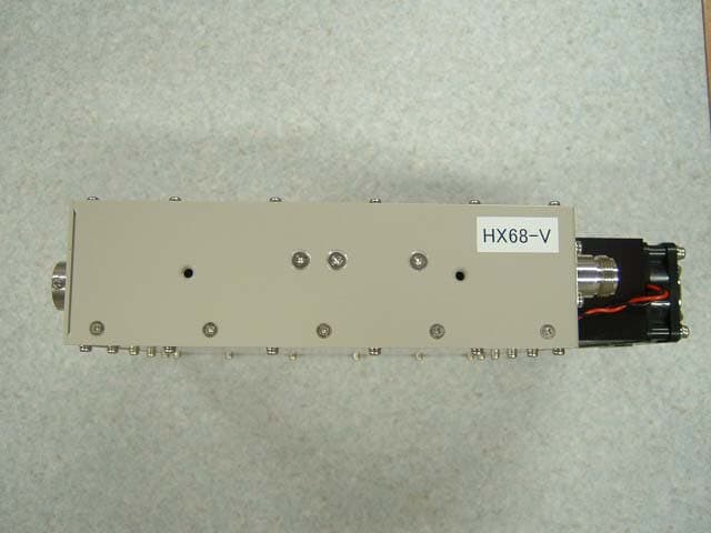
Click to zoom
Application Details
- Equipment Class
- TNB - Licensed Non-Broadcast Station Transmitter
- Date of Grant
- Nov 19, 2003
- Application Purpose
- Original Equipment
- Date of Application
- Nov 19, 2003
- Equipment Note
- UHF-FM Mobile Transceiver
- Frequency Range
- 458.03750000 - 458.98750000
- Country
- Japan
Documents & Files
Document Text
Text extracted from the exhibit documents filed with the FCC. Open a document above to read the original.
Users Manual
Recommended Installation Method for HX68-C/V is described as follows. 1. Installation Location A metal cabinet of approximately 300 mm (Wide) x 400 mm (Depth) x 600 mm (Height) with shelf boards to secure the equipment. 2. Storage Place The top shelf of a cabinet stores “HX69-C/V RF Combiner” and the lower shelf (shelves) stores one or more than one HX68-C/V. 3. Important Reminders in Installation Procedure A. HX68-C/V and HX69-C/V are secured to the shelf board with screws. At the installation, ensure to conduct the ground earth. B. Audio Input/Output and control and power supply wiring are done in the front of a cabinet. Wiring for high frequency between HX68-C/V and HX69-C/V is done at the back of a cabinet. Because a coaxial cable for HX68-C/V and HX69-C/V is wired at the back of a cabinet, HX68-C/V is installed in a direction in which its surface with the connector faces the backside of a cabinet. C. A ventilating hole is provided in the back of a cabinet in order for the heat generated from Receiver / Transceiver and Power Supply Equipment in a cabinet to be released to the outside easily. 4. Antenna Location The antenna is installed in which the distance from a human body is, in the worst case, no less than what is specified by the FCC regulations. -End-
Cover Letter(s)
American Telecommunications Certification Body Inc. 6731 Whittier Ave, McLean, VA 22101 October 21, 2003 RE: NEC System Integration & Construction FCC ID: RJGHX68V I have a few comments on this Application. 1.) Please supply a Test Report conforming to the Certification procedure of Part 2. 2.) Form 731 only shows voice modulation F3E. This is an incomplete emission designator. We must have it in a the form which includes the necessary bandwidth [i.e: 16K0F3E]. In addition, the Manual per page 4 indicates this device can also transmit data. Please provide an appropriate emission designator for data transmission. 3.) A Tune Up procedure is required for all Licensed transmitter submissions. 4.) The label and location exhibit indicates the label will be attached to the face of the EUT with adhesive. Please note the label must be permanently attached. Kindly indicate the method for insuring this label will be permanent. 5.) There are several documents which are identified as Confidential at the AmericanTCB.com website that are not identified in the Confidentiality Request letter. Please resolve this discrepancy. 6.) Please provide an RF Exposure estimation exhibit. 7.) Please note that additional information may be requested upon receipt if the Test Report. William H. Graff President and Examining Engineer mailto: [email protected] The items indicated above must be submitted before processing can continue on the above referenced application. Failure to provide the requested information may result in application termination. Correspondence should be considered part of the permanent submission and may be viewed from the Internet after a Grant of Equipment Authorization is issued. Please do not respond to this correspondence using the email reply button. In order for your response to be processed expeditiously, you must submit your documents through the AmericanTCB.com website. Also, please note that partial responses increase processing time and should not be submitted. Any questions about the content of this correspondence should be directed to the sender.
Cover Letter(s)
American Telecommunications Certification Body Inc. 6731 Whittier Ave, McLean, VA 22101 November 6, 2003 RE: NEC System Integration & Construction FCC ID: RJGHX68V The new revisions to this filing are substantially better than the first. However, I still have a few comments on this Application. 1.) Please provide Tune Up procedure for this device. 2.) Please provide updated Confidentiality Agreement. Do you really want to have the Parts List and Tune Up procedure available to the public at the FCC website? 3.) For Section 9, “Field Strength of Spurious Emissions”, the FCC accepted methodology for measuring transmitter radiated spurious is to use the substitution method described in TIA/EIA 603. Please review this document and provide revised information. 4.) Please provide RF Exposure Information using the antennas selected for this product. 5.) Please provide an installation manual or installation instructions for this product. 6.) Please provide information required under 2.1033(c)(6), (7) and (8). 7.) Please confirm that no digital intelligence or digital data will be transmitted by this device. William H. Graff President and Examining Engineer mailto: [email protected] The items indicated above must be submitted before processing can continue on the above referenced application. Failure to provide the requested information may result in application termination. Correspondence should be considered part of the permanent submission and may be viewed from the Internet after a Grant of Equipment Authorization is issued. Please do not respond to this correspondence using the email reply button. In order for your response to be processed expeditiously, you must submit your documents through the AmericanTCB.com website. Also, please note that partial responses increase processing time and should not be submitted. Any questions about the content of this correspondence should be directed to the sender.
External Photos
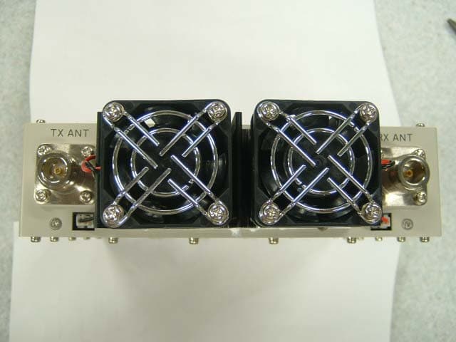
External Photo NEC System Integration & Construction,Ltd. FCC ID: RJGHX68V Front Rear External Photo NEC System Integration & Construction,Ltd. FCC ID: RJGHX68V Right Left External Photo NEC System Integration & Construction,Ltd. FCC ID: RJGHX68V Top Bottom
Internal Photos
Internal Photo NEC System Integration & Construction,Ltd. Model: HX68V FCC ID: RJGHX68V Internal Photo NEC System Integration & Construction,Ltd. Model: HX68V FCC ID: RJGHX68V Internal Photo NEC System Integration & Construction,Ltd. Model: HX68V FCC ID: RJGHX68V
RF Exposure Info
UL Apex Co., Ltd. EMC Head Office Division. 4383-326 Asama-cho, Ise-shi, Mie-ken 516-0021 JAPAN Telephone : +81 596 24 8116 Facsimile : +81 596 24 8124 RF Exposure Statement No.:23BE0140-HO-2 Applicant : NEC System Integration & Construction, Ltd. Type of Equipment : Radio Equipment Model No. : HX68-V FCC ID : RJGHX68V Radio frequency radiation exposure evaluation statement: NEC System Integration & Construction, Ltd. declares that Model: HX68-V complies with the definition of “Private Land Mobile Radio Services ” indicated in FCC 90 and complies with the limits for MPE for the General Population/Uncontrolled Exposure at 55 cm separation between the antenna and the body of user or nearby persons (Table 1(B) of FCC 1.1310). MPE Calculation: The Table 1(B) of FCC 1.1310 specifies the limits for MPE (Maximum Permissible Exposure) for General Population/Uncontrolled Exposure. The power density shall be below 0.305 mW/cm 2 for frequencies from 458.0375MHz to 458.9875MHz. The power density S is calculated by the following equation: S = (P x G) / (4πR 2 ) Where, S = Power Density in mW/cm 2 at 55 cm apart from the antenna P = 10000 mW (Maximum Conducted Power) G = 1. (Monopole Antenna Gain ;equal to 1.) R = 55 cm For : HX68-V S = 0.263066 mW/cm 2 Notes in the User’s Manual: IMPORTANT: To meet the FCC's RF Exposure Guidelines, model HX68-V should be used so that there is at least 55 centimeters of separation between the body of user or nearby persons and the antenna.
Test Report
Test report No.: 24BE0140-HO-2 Page : 24 of 40 Issued date : October 27, 2003 Revised date : November 10, 2003 FCC ID : RJGHX68V UL Apex Co., Ltd. Head Office EMC Lab. 4383-326 Asama-cho, Ise-shi, Mie-ken 516-0021 JAPAN Telephone : +81 596 24 8116 Facsimile : +81 596 24 8124 MF060b(10.04.03) SECTION 9: Field Strength of Spurious Emission Field Strength of Spurious Emission is measured with two kind of configuration, the one is with HX68-V only and the another is with HX68-V connected with HX69-V. 9.1 Test Procedure : FCC 2.1053 1) The HX68-V was aligned for transmitter operation on 458.5125MHz at full rated power. 2) The Carrier is modulated by a 2.5KHz tone at an input level 16dB greater than that necessary to produce 50 percent modulation. The input level shall be established at the frequency of maximum response of the audio modulation. 4) Output of HX68-V was connected with dummy load attenuator 40dB. 5) Tune-up the transmitter (EUT) 6) For each spurious measurement the receiving antenna is adjusted to the correct length for the frequency involved. These measurements are made from the lowest radio frequency generated in the EUT or 30MHz to the tenth harmonics of the carrier. 7) EUT was placed on a platform of nominal size, 1m by 1.5m, raised 1m above the conducting ground plane. Test was made with the antenna positioned in both the horizontal and vertical planes of polarization. The Radiated Electric Field Strength intensity has been measured in No.2 semi anechoic chamber (7.5x5.8x5.2m) with a ground plane and at a distance of 3m. The measuring antenna height was varied between 1 to 4m and EUT was rotated a full revolution in order to obtain the maximum value of the electric field intensity. The measurements were performed for both vertical and horizontal antenna polarization. 8) Exchanged the EUT to the Substitution Antenna, the measurement was set for the same height 1m as the EUT. The frequency below 1GHz of the Substitution Antenna was used as the Half wave dipole Antenna, which is harmonized with the measured frequency in 7). The frequency above 1GHz of the Substitution Antenna was used with Horn Antenna. The Substitution Antenna was connected with the Signal Generator, and the polarized electromagnetic radiation of the Substitution Antenna was matched with the one of the measuring Antenna, which was set with the Signal Generator to the measured frequency in 7). Then, we set with the Output power (CW) of the Signal Generator where the measuring electromagnetic field is equal to the measured value in 7). The measuring antenna height was varied between 1 to 4m to obtain the maximum receiving level. Its Output power of Signal Generator was recorded. 9) Effective radiated power was calculated by subtracting the cable loss and the attenuator loss connected between the Signal Generator and the Substitution Antenna from the Output power of the Signal Generator recorded in 8). For the usage of the Antenna (Horn Antenna) except for the Half wave dipole Antenna (2.14dBi) for the Substitution Antenna, the Effective radiated power was calculated by compensating the finite difference in the Antenna gain of the Half wave dipole Antenna, and Substitution Antenna.
Contact Information
Applicant
Jun Arai(Assistant Manager)
Technical Contact
Test Firm
UL Apex Co., Ltd.Tetsuya Hashimoto
Technical Specifications
| # | Rule Parts | Frequency Range | Power Output | Emission | Tolerance |
|---|---|---|---|---|---|
| 1 | 90.210 | 458.0375 MHz - 458.9875 MHz | 10 W | 11K0F3E | 2.5000000000 ppm |
Other Applications from NEC System Integration & Construction,Ltd.
RJGHX68C
Nov 19, 2003UHF-FM Mobile Transceiver
Equipment Class
TNB - Licensed Non-Broadcast Station Transmitter