FCCID.CO- FCC ID Database
HomeCompaniesEquipment ClassesSearch

© 2026 FCC ID Database. All rights reserved.

AboutContactData sourced from FCC public records
  1. Home/
  2. C-TECH UNITED CORP./
  3. RJK-BT2011A

RJK-BT2011ABluetooth Headset

C-TECH UNITED CORP.
Bluetooth Headset - FCC ID RJK-BT2011A - C-TECH UNITED CORP.
Click to zoom

Application Details

Equipment Class
DSS - Part 15 Spread Spectrum Transmitter
Date of Grant
Apr 05, 2004
Application Purpose
Original Equipment
Date of Application
Apr 05, 2004
Equipment Note
Bluetooth Headset
Frequency Range
2402.00000000 - 2480.00000000
Company
C-TECH UNITED CORP.
Country
Taiwan

Documents & Files

Select a file to view

Users Manual

↗

Cover Letter(s)

↗
↗
↗

External Photos

↗

ID Label/Location Info

↗
↗

Internal Photos

↗

Parts List/Tune Up Info

↗

Test Report

↗

Test Setup Photos

↗

Document Text

Text extracted from the exhibit documents filed with the FCC. Open a document above to read the original.

Users Manual

1 C-TECH UNITED CORP. Blue Tooth BT2011 User Manual 2 Preface C-TECH’s Bluetooth TM Headset BT2011 is a cordless mobile solution built on Bluetooth wireless technology. Please proceed the instructions before using your Headset What is Bluetooth Technology? The Bluetooth wireless Technology eliminates constraint of cables by making connection to any portable and stationary device realized. This is built on the technology that is based on a radio link that provides voice and data transmission. The Bluetooth wireless technology uses a worldwide available range of frequency to ensure communication compatibility throughout the globe. How the Headset is Used? For Headset to work, it must be used with mobile phone, PC or any device with Bluetooth technology that conforms to the Headset Profile. This User’s Guide concentrates on how to use the Headset with your mobile phone. When the Headset is connected to your mobile phone, calls can be made by using voice control (provided that this function is supported by your phone). Because the Headset is designed to keep your hands free, the phone can be tucked away in your pocket or in a bag. By using a three-way push button on the Headset, you can easily handle incoming and outgoing calls, and adjust the volume. 3 Operating Your Headset Overview To be able to use the Headset together with a mobile phone, or any device that you want to use with the Bluetooth Headset, it has to be compatible with Bluetooth wireless technology and supports the Headset Profile. In order to use the Headset with a mobile phone, you need to have a phone with Bluetooth capability built-in. Front Back 4 S1 : On/Off and Answer/End calls S2 : Decrease Volume S3 : Increase Volume Getting Started You should do the following prior to using the Headset with a phone or other device for the first time, z Decide on which ear you want to wear the headset (factory setup is for right-ear use). z Pair the Headset with a device (mobile phone). z Use appropriate C-TECH charger to charger the Headset The above stages are described in detail below. Right or Left Ear The direction of the ear clip has to be changed should you decide to wear the Headset on your left ear. To adjust the ear clip for left-ear use: Putting On the Headset 5 z Put on the Headset with the ear clip behind your ear. z Ensure the microphone is pointing toward your mouth. Turning the Headset On or Off To turn the Headset on z A short low tone will be heard when you press and hold the Headset button, followed by a short high tone. The Headset indicator light now flashes green, and flashes red when low battery is detected. To turn the Headset off 6 z A short high tone will be heard when you press and hold the Headset button followed by a short low tone. The Headset indicator light is now turned off. Pairing the Headset Pairing the Headset with the device you want to use with is required before starting to operate the Headset for the first time. Using a Mobile Phone with Built-in Bluetooth Capability. You can simply pair the Headset with your phone by adding it to a list of paired device in the phone. They will connect each other based on the recognition between the phone and the Headset. Putting Headset in Pairing Mode While the Headset is powered down, press and hold S1 for 5 seconds. Red and green LEDs flashing alternately will indicate the Headset is in Pairing Mode. The default Passkey required for pairing is 0000. If the Headset is not successfully paired within the Pairing Timeout period, it will automatically shutoff. <Reference> To pair the Headset with Ericsson’s (T39/T68/T68i/R520m) mobile phone: 1. In the phone, scroll the “Extras”, press YES, “Bluetooth”, press YES, “Paired devices”, press YES, ”Add device?”, press YES , “Phone initiates”, press YES. 2. The phone shows a list of device types that can be paired with it is displayed. Scroll the “Headset” and press YES. 3. Putting Headset in pairing mode, LED flash green and red alternately. 4. The phone commences searching for the Headset as soon as the Headset passkey “0000” is entered, and press YES.. 5. When the search is complete, the display shows a list of available devices, like “BT2011”, then press YES. 6. The preset Headset name may be modified to your own personal name tag now. Press YES. When pairing has been completed, the indicator light on the Headset flashes green. To pair the Headset with Nokia’s (6310/6310i/8910) mobile phone: 1. In the phone, select “Manu”, scroll to “Bluetooth”, press “Select”, select “On”, the phone will show “Bluetooth switched on” followed Bluetooth. 2. Putting Headset in pairing mode, LED flash green and red alternately. 3. Scroll to “Search for audio accessories”, press “select”, the phone will search for devices then list the devices found ”BT2011”. 4. Press “Select” then enter the passcode “0000”, press “OK”, the phone will show ”Connected to 7 BT2011”, then exit menu and back to “Search for audio accessories”. 5. Scroll to “View paired devices”, press “select”, will show device type “BT2011”. 6. Press “BT2011”, select “Options”, press “select”, scroll to “Request conn. authorization”, press “select”, select ”No “, press “select” to disable phone authorization, the indicator light on the Headset flashes green. Charging The Headset comes with a rechargeable battery included. The battery is not fully charged when it is new. For first time use, insert the adaptor into the Headset to charge until the indicator light turns green. z It takes 1-1.5hours to fully charge the battery. z To indicate that the Headset runs on low power, the Headset indicator light flashes red when the Headset is on. z When the Headset is turned off during the process of charging, the indicator light shows a steady red light, and flashes red when the Headset is on. z When the headset is turned off once the battery is fully charged, the indicator shows a steady green light, or shows green light if the Headset is on. z After battery fully charged, do not re…

Text truncated - open the document above for the full version.

Cover Letter(s)

Mike Kuo 4/6/2004 Hi Mike, The output power measurement is re-done and the test report is revised and attached. Thank you for your efforts. Best regard, Ting ----- Âà§eªÌ ting/ccsemc ©ó 2004/04/06 09:31 AM ----- -----Original Message----- From: CERTADM Sent: Wednesday, March 31, 2004 7:02 PM To: Mike Kuo Subject: C-TECH UNITED CORP. , FCC ID:RJK-BT2011A, AN04T3825 Notice_content ------------- Question #1: While doing the RF conducted output power tests, RBW=30kHz was used which is less than 20dB. Please redo output power measurement and submit the test plots. Best Regards Mike Kuo The items indicated above must be submitted before processing can continue on the above referenced application. Failure to provide the requested information within 30 days of the original e-mail date may result in application dismissal and forfeiture of the filing fee. Also, please note that partial responses increase processing time and should not be submitted. Any questions about the content of this correspondence should be directed to the e-mail address listed below the name of the sender. Mike Kuo <[email protected]> 2004/04/01 11:02 AM ¦¬¥ó¤H¡G "CCS-Taiwan, Ting (E-mail)" <[email protected]>, "CCS-Taiwan, Wklo (E-mail)" <[email protected]> °Æ¥»§Û°e¡G ¥D¦®¡G FW: C-TECH UNITED CORP. , FCC ID:RJK-BT2011A, AN04T3825

External Photos

Compliance Certification Services Inc. Report No: B40309201 Date of Issue: March 29, 2004 Page 1 of EXTERNAL PHOTOGRPHS OF EUT Compliance Certification Services Inc. Report No: B40309201 Date of Issue: March 29, 2004 Page 2 Compliance Certification Services Inc. Report No: B40309201 Date of Issue: March 29, 2004 Page 3

ID Label/Location Info

Label Location

Internal Photos

Compliance Certification Services Inc. Report No: B40309201 Date of Issue: March 29, 2004 Page 4 INTERNAL PHOTOGRPHS OF EUT Compliance Certification Services Inc. Report No: B40309201 Date of Issue: March 29, 2004 Page 5 Compliance Certification Services Inc. Report No: B40309201 Date of Issue: March 29, 2004 Page 6

Parts List/Tune Up Info

Walsin Technology Corporation MULTILAYER CERAMIC ANTENNA RFANT Series 2.4 GHz ISM Band Working Frequency P/N: RFANT5220110A0T Page 1 of 16 AS_RFANT5220110A0T_0 Feb. 2003 Walsin Technology Corporation Page 2 of 16 AS_RFANT5220110A0T_03 Feb-2003 FEATURES … Surface Mounted Devices with a small dimension of 5.2 x 2.0 x 1.1 mm 3 meet future miniaturization trend. … Embedded and LTCC (Low Temperature Co-fired Ceramic) technology is able to future integrate with system design as well as beautifying the housing of final product. … High Stability in Temperature / Humidity Change APPLICATIONS … Bluetooth … Wireless LAN … HormRF … ISM band 2.4GHz wireless applications DESCRIPTION Walsin Technology Corporation develops a new ceramic embedded antenna specified for 2.4 GHz ISM Band application, as shown in below “CONSTRUCTION”. Both of Wireless LAN IEEE 802.11b and Bluetooth TM typically located on this unlicensed frequency band which range covers from 2.4GHz to 2.4835GHz. To fulfil the friendly usage for antenna, this antenna has been designed to a typical 150MHz bandwidth through Walsin’s advanced LTCC (Low Temperature Co-fired Ceramic) technology and superior product design via 3D EM Simulation Skill. This antenna has a rectangular ceramic body with a tiny dimension of 5.2x 2.0 x 1.1 mm 3 meet the future SMT automation and miniaturization requirements on modern portable devices. CONSTRUCTION Fig 1. Outline of 2.4GHz Antenna – RFANT5220110A0T Fig 2. Dimension W T C W T C Soldering terminal Identification mark Feeding W T C W T C Soldering terminal Identification mark Feeding 2.0 ±0.2 mm 1.15 ±0.10 mm 5.2 ± 0.2 mm 0.30 ± 0.15 mm 0.30 ± 0.15 mm WTC 2.0 ±0.2 mm 1.15 ±0.10 mm 5.2 ± 0.2 mm 0.30 ± 0.15 mm 0.30 ± 0.15 mm WTC Walsin Technology Corporation Page 3 of 16 AS_RFANT5220110A0T_03 Feb-2003 SOLDER LAND PATTERN DESIGN Figure ELECTRICAL CHARACTERISTICS Item Specification Working Frequency Range 2.4 GHz 2.5GHz Gain 2 dBi (Typical) VSWR 2 max. Polarization Linear Azimuth Beamwidth Omni-directional Impedance 50Ω Rated Power (max.) 3 Watts Maximum Input Power 5 Watts for 5 minutes Remark: The specification is defined based on the test board dimension as in below To 50Ω RF I/O GROUND 6.4 1.0 1.0 4.4 2.0 Ground Soldering Pad 50 ΩTransmission Line Unit : mm 1.0 To 50Ω RF I/O GROUND 6.46.4 1.0 1.0 4.4 2.0 Ground Soldering Pad 50 ΩTransmission Line Unit : mm 1.0 Walsin Technology Corporation Page 4 of 16 AS_RFANT5220110A0T_03 Feb-2003 Antenna on Test Board ( FR4 Thickness 0.8mm) Antenna S11 on Test Board Bandwidth >150MHzBandwidth >150MHz Empty Area Empty Area 18x9 mm 50ΩFeed line GROUND 30x18 mm 1mm 3.3mm 1.5mm WTC 2.5mm 18mm Empty Area Empty Area 18x9 mm 50ΩFeed line GROUND 30x18 mm 1mm 3.3mm 1.5mm WTCWTC 2.5mm 18mm Walsin Technology Corporation Page 5 of 16 AS_RFANT5220110A0T_03 Feb-2003 z Y RADIATION PATTERN Radiation Pattern and Gain were dependent on measurement board design. The specification of RFANT5220110A0T antenna was measured based on the PCB size and installation position as shown in the below figure Test Board Vertical Horizontal Y - Z Plane Average Gain= -3.22 dBi Peak Gain = 1.69 dBi Average Gain = -0.82 dBi Peak Gain= -5.42 dBi Average Gain=-8.98 dBi X - Z Plane Average Gain= -3.24 dBi Peak Gain= -5.97 dBi Average Gain= -8.61dBi Peak Gain= 2.66 dBi Average Gain= -0.91 dBi Empty Area GROUND 30x18 mm WTC X Y Z Empty Area GROUND 30x18 mm WTCWTC X Y Z X Y Z Y Z WTC X Y Z WTC X Y Z WTC X Y Z WTC X Y Z WTC X Y Z WTC X z Y z X z X Walsin Technology Corporation Page 6 of 16 AS_RFANT5220110A0T_03 Feb-2003 X Y X - Y Plane Average Gain= -3.12 dBi Peak Gain= -5.97 dBi Average Gain= -9.24dBi Peak Gain= 2.59 dBi Average Gain= -0.68 dBi X Y Walsin Technology Corporation Page 7 of 16 AS_RFANT5220110A0T_03 Feb-2003 APPLICATION INFORMATION (1). RFANT5220110A0T on Card-Bus Layout Proposal: (110mm x 45mm, unit in mm) Antenna 1 X Y Z Antenna 2 Housing Add via holes to Connect ground and land pad L, C Matching Network (A). Antenna Installation -Upside 45 mm 110 mm (B). Ground Design - Backside Add via holes to Connect ground and land pad L, C Matching Network (A). Antenna Installation -Upside 45 mm 110 mm (B). Ground Design - Backside 45 mm 110 mm (B). Ground Design - Backside Walsin Technology Corporation Page 8 of 16 AS_RFANT5220110A0T_03 Feb-2003 S11 for Antenna - 1 S11 for Antenna - 2 2.0GHz 3.0GHz -12.216dB @ 2.40GHz -19.236dB @ 2.45GHz -16.490dB @ 2.50GHz 2.0GHz 3.0GHz -12.216dB @ 2.40GHz -19.236dB @ 2.45GHz -16.490dB @ 2.50GHz 2.0GHz 3.0GHz -13.829dB @ 2.40GHz -22.511dB @ 2.45GHz -15.749dB @ 2.50GHz 2.0GHz 3.0GHz -13.829dB @ 2.40GHz -22.511dB @ 2.45GHz -15.749dB @ 2.50GHz Walsin Technology Corporation Page 9 of 16 AS_RFANT5220110A0T_03 Feb-2003 Radiation Pattern at 2.45GHz: Antenna – 1: E Plane H Plane Peak Gain = +3.58 dBi @ 155° Average Gain = -1.36 dBi Peak Gain= -0.17 dBi @ 165° Average Gain= -2.69dBi Antenna – 2: E Plane H Plane Peak Gain = +4.26 dBi @ 195° Average Gain = -1.30 dBi Peak Gain = +0.50 dBi @ 210° Average Gain = -2.77 dBi i 270 ° 10.00 90 ° 180 ° 0.00 -10.00 -20.00 -30.00 -40.00 Unit in dBi 270 ° 10.00 90 ° 180 ° 0.00 -10.00 -20.00 -30.00 -40.00 Unit in dBi 270 ° 10.00 90 ° 180 ° 0.00 -10.00 -20.00 -30.00 -40.00 Unit in dBi 270 ° 10.00 90 ° 180 ° 0.00 -10.00 -20.00 -30.00 -40.00 Unit in dBi 270 ° 10.00 90 ° 180 ° 0.00 -10.00 -20.00 -30.00 -40.00 Unit in dBi 270 ° 10.00 90 ° 180 ° 0.00 -10.00 -20.00 -30.00 -40.00 Unit in dBi 270 ° 10.00 90 ° 180 ° 0.00 -10.00 -20.00 -30.00 -40.00 Unit in dBi 270 ° 10.00 90 ° 180 ° 0.00 -10.00 -20.00 -30.00 -40.00 Unit in dBi 270 ° 10.00 90 ° 180 ° 0.00 -10.00 -20.00 -30.00 -40.00 Unit in dBi 270 ° 10.00 90 ° 180 ° 0.00 -10.00 -20.00 -30.00 -40.00 Unit in dBi 270 ° 10.00 90 ° 180 ° 0.00 -10.00 -20.00 -30.00 -40.00 Unit in dBi 270 ° 10.00 90 ° 180 ° 0.00 -10.00 -20.00 -30.00 -40.00 Unit in dBi Walsin Technology Corporation Page 10 of 16 AS_RFANT5220110A0T_03 Feb-2003 Housing Antenna 1Antenna 2 X Y Z Housing Antenna 1Antenna 2 X Y Z (2). RFANT5220110A0T on Com…

Text truncated - open the document above for the full version.

Test Report

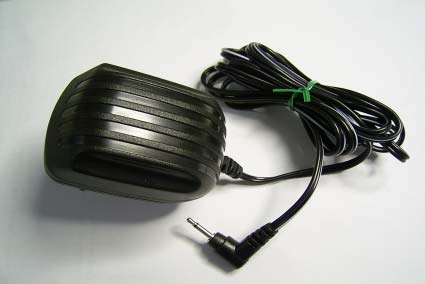
Compliance Certification Services Inc. Report No: B40309201-RP FCC ID:RJK-BT2011A Date of Issue: March 26, 2004 Note: This report shall not be reproduced except in full, without the written approval of Compliance Certification Services Inc. This document may be altered or revised by Compliance Certification Services Inc. personnel only, and shall be noted in the revision section of the document Page 1 of 58 FCC 47 CFR PART 15 SUBPART C TEST REPORT For C-TECH UNITED CORP. Bluetooth Headset Model: BT2011 Trade Name: C-TECH Prepared for C-TECH UNITED CORP. 5F, No. 665, Sec. 3, Chung Chen Rd., Hsin Chuang City, Taipei Hsien, Taiwan, R.O.C. Prepared by Compliance Certification Services Inc. No. 81-1, Lane 210, Bade Rd. 2, Luchu Hsiang, Taoyuan Hsien, (338) Taiwan, R.O.C. TEL: 886-3-324-0332 FAX: 886-3-324-5235 Compliance Certification Services Inc. Report No: B40309201-RP FCC ID:RJK-BT2011A Date of Issue: March 26, 2004 Page 2 TABLE OF CONTENTS 1. TEST RESULT CERTIFICATION............................................................................................. 3 2. EUT DESCRIPTION .................................................................................................................... 4 3. TEST METHODOLOGY ............................................................................................................. 5 3.1 EUT CONFIGURATION.............................................................................................................. 5 3.2 EUT EXERCISE......................................................................................................................... 5 3.3 GENERAL TEST PROCEDURES.................................................................................................. 5 3.4 FCC PART 15.205 RESTRICTED BANDS OF OPERATIONS ............................................. 6 3.5 DESCRIPTION OF TEST MODES................................................................................................. 6 4. INSTRUMENT CALIBRATION................................................................................................. 7 5. FACILITIES AND ACCREDITATIONS ................................................................................... 8 5.1 FACILITIES.............................................................................................................................. 8 5.2 EQUIPMENT............................................................................................................................. 8 5.3 LABORATORY ACCREDITATIONS AND LISTING....................................................................... 8 5.4 TABLE OF ACCREDITATIONS AND LISTINGS............................................................................ 9 6. SETUP OF EQUIPMENT UNDER TEST ................................................................................ 10 6.1 SETUP CONFIGURATION OF EUT............................................................................................ 10 6.2 SUPPORT EQUIPMENT .................................................................................................. 10 7. FCC PART 15.247 REQUIREMENTS...................................................................................... 11 7.1 PEAK POWER......................................................................................................................... 11 7.2 PEAK POWER SPECTRAL DENSITY......................................................................................... 14 7.3 BAND EDGES MEASUREMENT ..................................................................................... 17 7.4 FREQUENCY SEPARATION ............................................................................................ 22 7.5 NUMBER OF HOPPING FREQUENCY............................................................................ 27 7.6 TIME OF OCCUPANCY (DWELL TIME) ........................................................................ 29 7.7 RADIO FREQUENCY EXPOSURE............................................................................................. 37 7.8 SPURIOUS EMISSIONS ...................................................................................................... 40 7.9 POWERLINE CONDUCTED EMISSIONS.................................................................................... 53 APPENDIX 1 PHOTOGRPHS OF TEST SETUP.......................................................................... 57 Compliance Certification Services Inc. Report No: B40309201-RP FCC ID:RJK-BT2011A Date of Issue: March 26, 2004 Page 4 2. EUT DESCRIPTION Product Bluetooth Headset Trade Name C-TECH Model Number BT2011 Model Discrepancy N/A Power Supply Model: DVR-0520-3512 Input: AC 120V, 60Hz, 60mA Output: DC 5V, 200mA Frequency Range 2402 – 2480MHz Transmit Power 0.55dBm Modulation Technique GFSK Transmit Data Rate 1MHz Number of Channels 79 Channels Antenna Designation Chip Antenna Temperature Range 0 ~ + 55°C Note: This submittal(s) (test report) is intended for FCC ID: RJK-BT2011A filing to comply with Section 15.207, 15.209 and 15.247 of the FCC Part 15, Subpart C Rules. Compliance Certification Services Inc. Report No: B40309201-RP FCC ID:RJK-BT2011A Date of Issue: March 26, 2004 Page 5 3. TEST METHODOLOGY The tests documented in this report were performed in accordance with ANSI C63.4. Radiated testing was performed at an antenna to EUT distance 3 meters. 3.1 EUT CONFIGURATION The EUT configuration for testing is installed on RF field strength measurement to meet the Commissions requirement and operating in a manner that intends to maximize its emission characteristics in a continuous normal application. 3.2 EUT EXERCISE The EUT was operated in the engineering mode to fix the Tx frequency that was for the purpose of the measurements. According to its specifications, the EUT must comply with the requirements of the Section 15.207, 15.209 and 15.247 under the FCC Rules Part 15 Subpart C. 3.3 GENERAL TEST PROCEDURES Conducted Emissions The EUT is …

Text truncated - open the document above for the full version.

Test Setup Photos

Compliance Certification Services Inc. Report No: B40309201-RP FCC ID:RJK-BT2011A Date of Issue: March 26, 2004 Page 57 APPENDIX 1 PHOTOGRPHS OF TEST SETUP Radiated Emission Set up Photos Compliance Certification Services Inc. Report No: B40309201-RP FCC ID:RJK-BT2011A Date of Issue: March 26, 2004 Page 58 Conducted Emission Set Up Photos

Contact Information

Applicant

Karl Hung(General Manager)
[email protected]886-2-2901-6600Fax: 886-2-2908-8534

Test Firm

Compliance Certification Services Inc.Tony Houng
[email protected]88633240332Fax: 88633245225

Technical Specifications

#Rule PartsFrequency RangePower Output
115C2.40 GHz - 2.48 GHz1.00 mW
Confidentiality
Long Term
Grant Notes
Output power listed is conducted. This device and its antenna(s) must not be co-located or operating in conjunction with any other antenna or transmitter. End-users must be provided with specific operating instructions for satisfying RF exposure compliance requirements.

Other Applications from C-TECH UNITED CORP.
Bluetooth Headset - FCC ID RJK-BT201PH - C-TECH UNITED CORP.
RJK-BT201PH

Bluetooth Headset

Nov 17, 2003

Equipment Class

DSS - Part 15 Spread Spectrum Transmitter