RJM-ENGAGEAudience response system
ENJOY TECHNOLOGY CO., LIMITED
Click to zoom
Application Details
- Equipment Class
- JBP - Part 15 Class B Computing Device Peripheral
- Date of Grant
- Mar 05, 2013
- Application Purpose
- Original Equipment
- Date of Application
- Mar 05, 2013
- Equipment Note
- Audience response system
- Country
- China
Documents & Files
Document Text
Text extracted from the exhibit documents filed with the FCC. Open a document above to read the original.
Users Manual
Users guide This product use 2.4G radio frequency technology, applied for polling, voting, training, education, quiz... etc. One complete system includes software and hardware. Hardware includes receiver, keypads and cable. Receiver: Dimension(mm):137×137×50, half ball Weight: 0.5 kg Working temperature:0-40 Working relative humidity:0-90% Working Power consumption: 5W Receiving angel and distance for receiving: 360degree. Function: connect to PC, receiving the signals from the keypads Functions of the receiver parts: 1. Power indicator light (red): power on, light on; power off, light off; 2. Communication indicator light (yellow): when the receiver gets the order from the PC, light on; 3. Status indicator light (blue): when the receiver is activated, light on. 4. Connection port: used for connect cable. 5. JP1 is the port for RJ-45 standard network card, use standard cable to connect to the USB port of PC. U2-U5 are WM2500LP(RF CHIPSET:CC2500)2.4G radio frequency mould, they are used for transmit and receive radio signals from the keypads.SN75179 is difference driver receiver and transmit IC. U7 is 24c serial memorizer, which connected to CUP P89LV51RD2BN via data timer cable. 24.576M Crystal oscillator X1 support the timer signal for CPU P89LV51RD2BN.CPU P89LV51RD2BN controls the working mode of every mould, operating the orders from the computer, and transmits or receives via moulds. P89LV51RD2BN send the signals which have been disposed to the computer. The receiver only one working mode is 4 modules transmit and receive simultaneously. these 4 RF modules and 4 antennas own the exactly same specification and RF parameters. Keypads 1 Specification Dimension: 5.3cm*11.6cm*1.5cm Transmitter angle: 360 degree Batteries: 2 AAA ordinary batteries or alkalescence batteries Function: voting or answering, sending signals to receiver 2. Functions of the keypads’ parts: 2.1LCD display area (as pictures below) 2.1.1 Keypads ID display, from 0001 to 9999 2.1.2 Capital / lowercase input indicator 2.1.3status indicate: “ ”,inputting or editing, “--”Stop answering, “>>”sending signals, “OK”proceedings (sending signals) successfully, “ ” proceedings (sending signals) failed, “”no connection with the receiver, “ ”Searching the signal of the receiver 2.1.4 Working mode indicator 2.1.5power volume indicator 2.2Buttons area (details and name of the button may be different printed for different mould) Includes function button, input button and combination button 2.2.1 Function buttons Ok: confirm sending or handling C: clear signals or cancel < ,> :left, right, up, down, forward, downward Power button: power on/ off, capital/lowercase input Input buttons: 1-10, A-I, symbol ’ and : Agree, objective and abstain Fn combination button Cable For getting power from PC; For data communication with receiver and PC One port is RJ45, another port is USB port. Test method: 1. Connect the cable to the PC, the system will install USB driver automatically; 2. Open the test software: “ WindowsApplication1.exe”, as below: 3. Press the red circled button of 1 and 2 by order, the system will prompt the word “ok”, confirm it, then the green light of the receiver will flashing. 4. After pressing the power key on the keypads, it will search the signals of the receiver automatically. Press the buttons one by one, and you will find the result of the receiver got at the red circle 3. FCC Certification Requirements Caution: Any changes or modifications in construction of this device which are not expressly approved by the party responsible for compliance could void the user's authority to operate the equipment. This device complies with part 15 of the FCC Rules. Operation is subject to the following two conditions: (1) This device may not cause harmful interference, and (2) This device must accept any interference received, including interference that may cause undesired operation. The manufacturer is not responsible for any radio or TV interference caused by unauthorized modifications to this equipment. Such modifications could void the user’s authority to operate the equipment. This equipment has been tested and found to comply with the limits for a Class B digital device, pursuant to Part 15 of the FCC Rules. These limits are designed to provide reasonable protection against harmful interference in a residential installation. This equipment generates, uses and can radiate radio frequency energy and, if not installed and used in accordance with the instructions, may cause harmful interference to radio communications. However, there is no guarantee that interference will not occur in a particular installation. If this equipment does cause harmful interference to radio or television reception, which can be determined by turning the equipment off and on, the user is encouraged to try to correct the interference by one or more of the following measures: - Reorient or relocate the receiving antenna. - Increase the separation between the equipment and receiver. - Connect the equipment into an outlet on a circuit different from that to which the receiver is connected. - Consult the dealer or an experienced radio/TV technician for help. IC NOTE: Le présent appareil est conforme aux CNR d'Industrie Canada applicables aux appareils radio exempts de licence. L'exploitation est autorisée aux deux conditions suivantes : (1) l'appareil ne doit pas produire de brouillage, et (2) l'utilisateur de l'appareil doit accepter tout brouillage radioélectrique subi, même si le brouillage est susceptible d'en compromettre le fonctionnement. This device complies with Industry Canada licence-exempt RSS standard(s). Operation is subject to the following two conditions: (1) this device may not cause interference, and (2) this device must accept any interference, including interference that may cause undesired operation of the device. Caution: Any changes or modifications in construction of this device which are not expressly approved by the party responsi…
Text truncated - open the document above for the full version.
Cover Letter(s)
ENJOY TECHNOLOGY CO., LIMITED UNIT 04,7/F BRIGHT WAY TOWER NO.33 MONG KOK RD KL Hong Kong China Confidentiality Request Letter Page 1 of 1 Rev 2.0 January 29, 2013 To: Federal Communications Commission Authorization and Evaluation Division 7435 Oakland Mills Road Columbia, MD Permanent Confidentiality Request Confidentiality Request regarding application for certification of FCC ID: RJM-ENGAGE We hereby request confidential treatment of information accompanying this application as outlined below: - Block Diagram - Operational Description - Schematic The above materials contain trade secrets and proprietary information not customarily released to the public. The public disclosure of these materials may be harmful to the applicant and provide unjustified benefits to its competitors. The applicant understands that pursuant to Section 0.457 & 0.459 of the Rules, disclosure of this application and all accompanying documentation will not be made before the date of the Grant for this application. Sincerely, Client’s signature: Client’s name / title: Xiaoling Chen / Manager Contact information / address: UNIT 04,7/F BRIGHT WAY TOWER NO.33 MONG KOK RD KL Hong Kong China TEL: 00852-27935511 FAX: 00852-27935511 E-mail: [email protected]
External Photos
External Photo USB Port RJ45 port
ID Label/Location Info
FCC Certification Label FCC ID: RJM-ENGAGE This device complies with Part 15 of the FCC Rules. Operation is subject to the following two conditions: 1. This device may not cause harmful interference, and 2. This device must accept any interference received, including interference that may cause undesired operation. Label Location on EUT EUT View/ FCC ID Label Location
Internal Photos
Internal Photo these 4 RF modules and 4 antennas own the exactly same specification and RF parameters Antenna 4 3 2 1
Test Report
FCC PART 15 CLASS B EMI MEASUREMENT AND TEST REPORT For ENJOY TECHNOLOGY CO., LIMITED UNIT 04,7/F BRIGHT WAY TOWER NO.33 MONG KOK RD KL Hong Kong China FCC ID: RJM-ENGAGE January 29, 2013 This Report Concerns: Original Report Equipment Type: Audience response system Test Engineer: Anna Lv Test Engineer of performing the tests: Hans Hu Report No.: BST120015721Y-1ER-3 Receive EUT Date/Test Date: January 02, 2013 / January 02, 2013- January 29, 2013 Reviewed By: Mike Moo Prepared By: Shenzhen BST Technology Co.,Ltd. 3F,Weames Technology Building, No. 10 Kefa Road, Science Park, Nanshan District,Shenzhen,Guangdong,China Tel: 0755-26747751-3 Fax: 0755-26747751-3 ext.826 Note: The test report is specially limited to the above company and this particular sample only. It may not be duplicated without prior written consent of Shenzhen BST Technology Co.,Ltd. This report must not be used by the client to claim product certification,approval,or endorsement by NVLAP, NIST or any agency of the US Government. FCC ID: RJM-ENGAGE BST120015721Y-1ER-3 Page 2/17 TABLE OF CONTENTS 1. GENERAL INFORMATION .................................................................................................... 3 1.1. Report information............................................................................................................ 3 2. PRODUCT DESCRIPTION ...................................................................................................... 4 2.1. EUT Description ............................................................................................................... 4 2.2. Block Diagram of EUT Configuration ............................................................................. 4 2.3. Support Equipment List .................................................................................................... 4 2.4. Test Conditions .................................................................................................................5 3. TEST RESULTS SUMMARY ................................................................................................... 6 4. TEST EQUIPMENT USED ....................................................................................................... 7 5. CONDUCTED EMISSION TEST............................................................................................. 8 5.1. Measurement Uncertainty................................................................................................. 8 5.2. Block Diagram of Test Setup............................................................................................ 8 5.3. Test Standard .................................................................................................................... 8 5.4. Conducted Emission Limit(Class B) ................................................................................ 9 5.5. EUT Configuration on Test .............................................................................................. 9 5.6. Operating Condition of EUT ............................................................................................ 9 5.7. Test Procedure ..................................................................................................................9 5.8. Test Result ........................................................................................................................ 9 6. RADIATED EMISSION MEASUREMENT ......................................................................... 12 6.1. Measurement Uncertainty............................................................................................... 12 6.2. Block Diagram of EUT Configuration ........................................................................... 12 6.3. Test Standard ..................................................................................................................12 6.4. Radiated Emission Limit(Class B) ................................................................................. 13 6.5. EUT Configuration on Test ............................................................................................ 13 6.6. Operating Condition of EUT .......................................................................................... 13 6.7. Test Procedure ................................................................................................................ 14 6.8. Test Result ...................................................................................................................... 14 FCC ID: RJM-ENGAGE BST120015721Y-1ER-3 Page 3/17 1. GENERAL INFORMATION 1.1. Report information 1.1.1.This report is not a certificate of quality; it only applies to the sample of the specific product/equipment given at the time of its testing. The results are not used to indicate or imply that they are application to the similar items. In addition, such results must not be used to indicate or imply that BST approves recommends or endorses the manufacture, supplier or use of such product/equipment, or that BST in any way guarantees the later performance of the product/equipment. 1.1.2.The sample/s mentioned in this report is/are supplied by Applicant, BST therefore assumes no responsibility for the accuracy of information on the brand name, model number, origin of manufacture or any information supplied. 1.1.3.Additional copies of the report are available to the Applicant at an additional fee. No third part can obtain a copy of this report through BST, unless the applicant has authorized BST in writing to do so. Test Facility - The test site used to collect the data is located on the address of Global United Technology Service Co., Ltd (FCC Registered Test Site Number: 600491) on 2nd Floor, Block No.2, Laodong Industrial Zone, Xixiang Road Baoan District, Shenzhen, China 518102 The Test Site is constructed and calibrated to meet the FCC requirements. FCC ID: RJM-ENGAGE BST120015721Y-1ER-3 Page 4/17 2. PRODUCT DESCRI…
Text truncated - open the document above for the full version.
Test Setup Photos
Radiated emissions test Conducted emissions test
Contact Information
Applicant
Xiaoling Chen
Test Firm
Global United Technology Service Co., LtdRobinson Lo
Technical Specifications
| # | Rule Parts | Frequency Range | Power Output |
|---|---|---|---|
| 1 | 15B | - | - |
Other Applications from ENJOY TECHNOLOGY CO., LIMITED
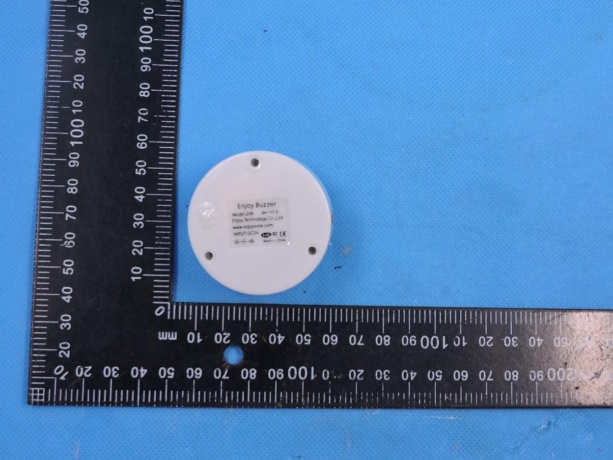
RJM206305306215
Dec 07, 2022Buzzer clicker galaxy audience response system
Equipment Class
DXX - Part 15 Low Power Communication Device Transmitter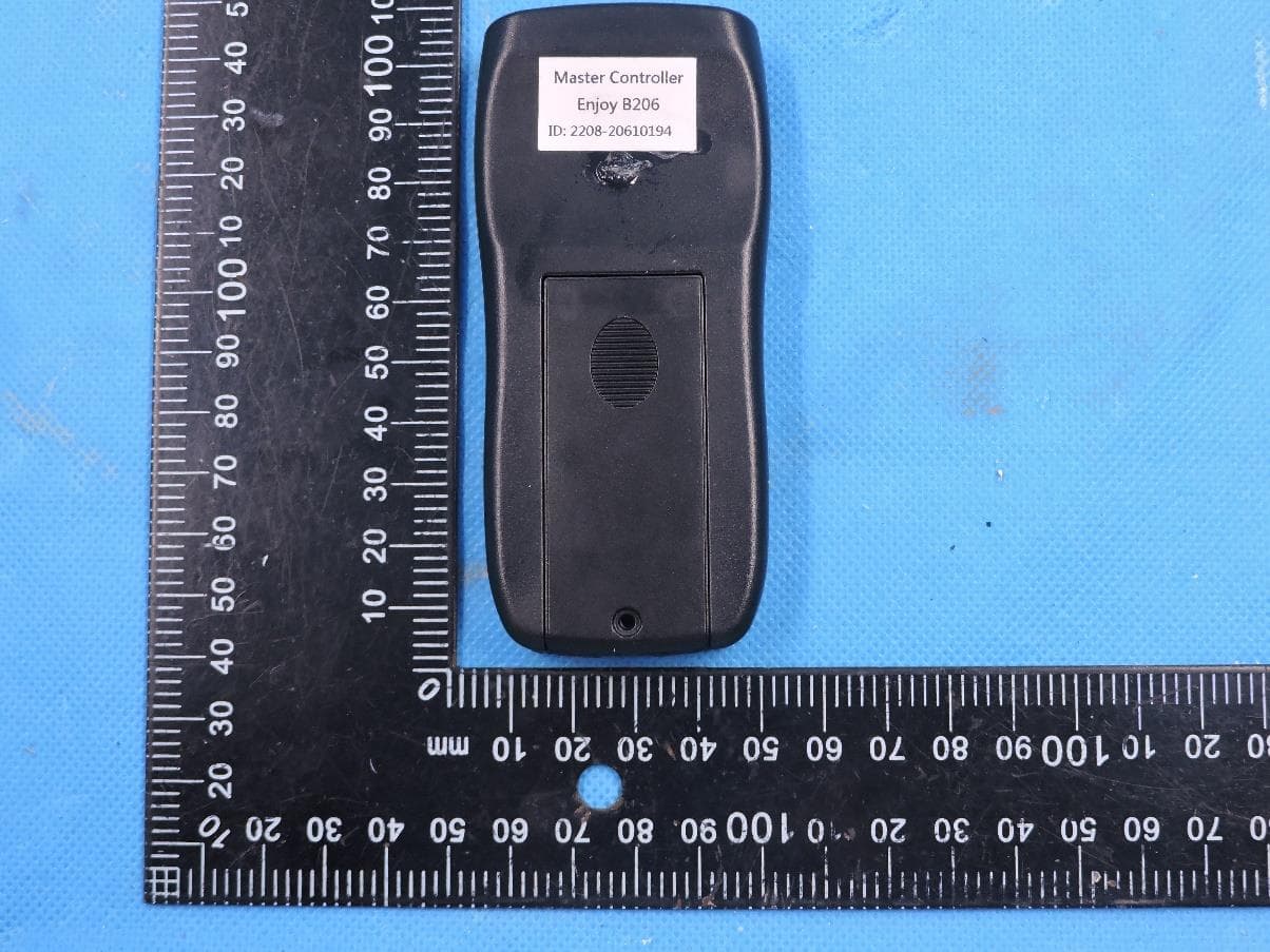
RJM206205306237
Dec 06, 2022Buzzer clicker galaxy audience response system
Equipment Class
DXX - Part 15 Low Power Communication Device TransmitterRJM-RFX19
Feb 28, 2013Audience response system
Equipment Class
DXX - Part 15 Low Power Communication Device Transmitter