RKYOM-1Over modulated pulsed output ISM
Plasma Sonics Ltd. Co.
Click to zoom
Application Details
- Equipment Class
- 8CC - Part 18 Consumer Device
- Date of Grant
- May 03, 2004
- Application Purpose
- Original Equipment
- Date of Application
- May 03, 2004
- Equipment Note
- Over modulated pulsed output ISM
- Frequency Range
- 27.12500000 - 27.12500000
- Company
- Plasma Sonics Ltd. Co.
- Country
- United States
Documents & Files
Document Text
Text extracted from the exhibit documents filed with the FCC. Open a document above to read the original.
Users Manual
OM-1 Transmitter Plasma Sonics Ltd. Co. Applications The OM-1 is a 27.125 MHz pulsed RF, ISM band transmitter. It has been designed to serve as a stand alone transmitter, or utilized with appropriate power amplification and harmonic output suppression to drive: 1. RF powered Lasers – May be used for cutting and welding of many different materials such as plastic and metals. 2. Pulsed short wave diathermy instruments 3. Pulsed RF, non thermal, frequency response based therapeutic instruments. 4. Gas plasma generation – Thermal and Non Thermal. RF excited gas plasmas are useful for electronics manufacturing and sterilization. 5. RF induction welders. 6. RF excited, UV emitting plasma tube for sterilization/decontamination of large surface areas.
Users Manual
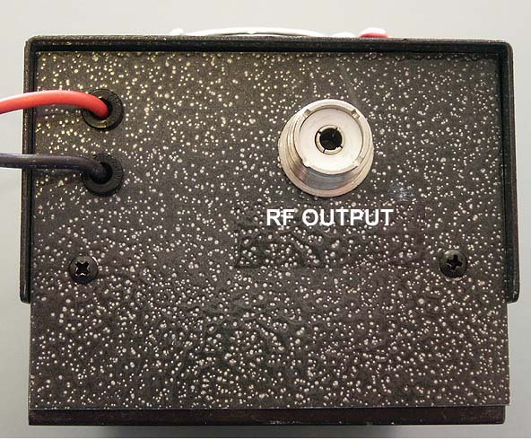
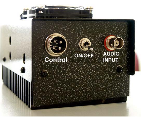
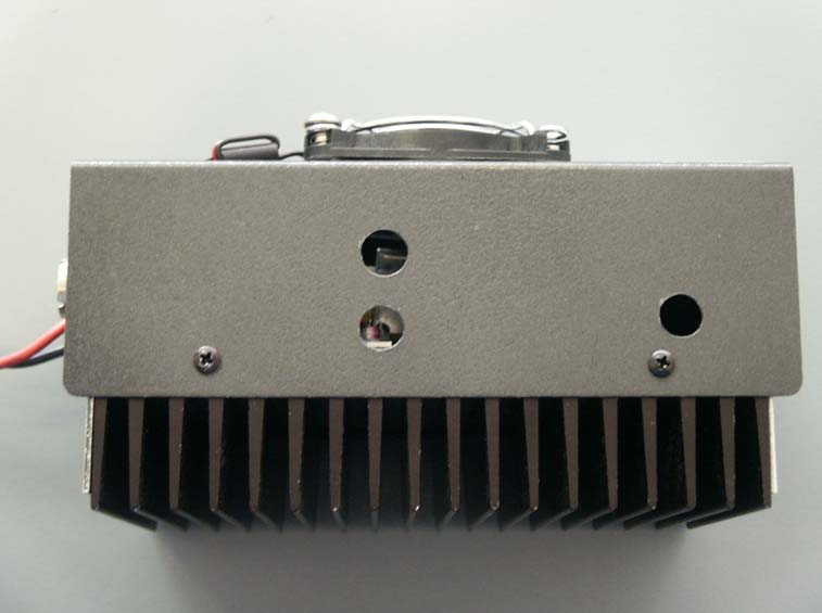
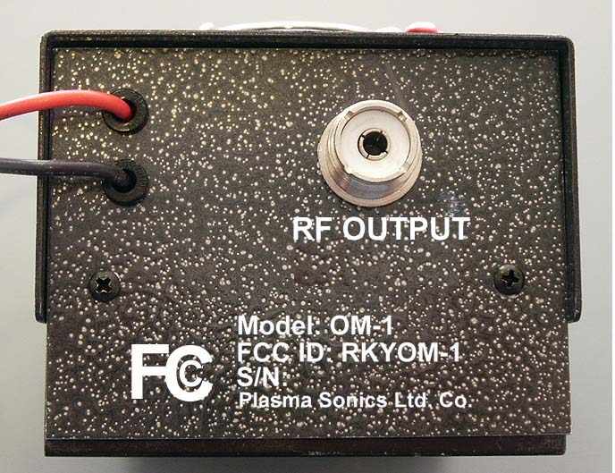
OM-1 Transmitter Plasma Sonics Ltd. Co PLEASE READ THIS OPERATIONS MANUAL PRIOR TO USAGE OF YOUR NEW OM-1 TRANSMITTER! FAILURE TO FOLLOW INSTRUCTIONS CAN RESULT IN DAMAGE TO YOUR NEW TRANSMITER ! Your new OM-1 Transmitter is designed as a pulsed RF driver for a variety of different instruments. It is designed to either be used in stand alone usage, or to be used in conjunction with an RF amplifier. Utilization of the OM-1 with an amplifier will necessitate the addition of some sort of harmonic suppression to the amplifiers output. The OM-1 is designed specifically for square wave audio modulation. Do not use less than a 50% duty cycle, and preferably a 70% duty cycle, square wave, for modulation purposes. The front side of the OM-1 has an on-off switch, a BNC connector, and a 4 pin microphone connector. The OM-1 is not designed for voice communication! The 4 pin connector allows one to use a computer controlled relay system to automatically turn the transmitter function on and off. The OM-1 is extremely simple to use, there two primary rule to remember: 1. The OM-1 is extremely sensitive to the input square wave power level! Excessive voltage and current can destroy the audio amplifier chip! Do Not !!! attempt to operate your OM-1 until after reading all instructions and setting input voltage from your frequency generator to an absolute minimum. 2. Do not operate (transmit) your OM-1 without being connected to some sort of load! Preparing The OM-1 For Use 1. Make certain all power switches are in the off position. This includes the power supply , the OM-1 transmitter, and the frequency generator. 2. Most frequency generators will lack any ability to computer control the OM-1. Use a BNC cable to connect your frequency generator output to the input BNC connector on the OM-1. Make certain power output is set to a minimum! Many frequency generators will have a –db button or buttons . Push ALL of these in. 3. Connect the power wire with the fuse in it, found on the back side of the OM-1, to the positive side of a 13.8 volt, 5 ampere or greater , power supply. 4. Connect the negative power wire on the back of the OM-1 to the negative side of a 13.8 volt power supply. 5. Connect a coaxial cable to the SO-239 connector on the back side of the OM-1. The other end of the cable should be connected to an antenna tuner or some sort of pre balanced load, such as an antenna, dummy load, laser plasma tube etc. . 6. Turn on the power supply, the fan should start running on the top of the OM-1. Turn on transmitter with a connected appropriate load . It is important that SWR values be balanced. The OM-1 has been tested for prolonged operational times with poor SWR’s . It has survived 30 minutes operation with SWR’s of 3 to 3.5. If your antenna or load is not balanced to the OM-1, you will risk damaging the OM-1. It is highly suggested that you balance SWR using an impedance matcher of some sort ( antenna tuner) between the OM-1 and it’s load. 7. Turn on frequency generator set to about 3000 Hz . Slowly start increasing output power level of your frequency generator until power level of the OM-1 maximizes. This power level is best seen on the SWR meter of an antenna tuner. Continue to increase audio level until power output of transmitter drops. Once a drop in power level is noted, quickly reduce audio output level from the frequency generator until power output of the OM-1 once again maximizes. Note where this output is, then decrease output level of the frequency generator till power starts to drop. Note where this level is. Operate the OM-1 at an output level half way between these maximum and minimum audio output settings. Do not drive the OM-1 on the edge of maximum audio input voltage! 8. In most applications the output level of a frequency generator can be set at between 0.3 and 0.5 volts P-P using an oscilloscope. Some frequency generators do not have much current output and these may take from 3 to 7 volts p-p to maximize output of the OM-1. 9. 0.4 volts output from a frequency generator is very low! This can easily be exceeded if one is not careful. Once set the OM-1 should provide years of trouble free operation. 10. It is advised that only one input be used with the OM-1 at a time. That is use either the BNC input or the 4 pin input, do not have both connected to separate frequency generators at the same time. OM-1 Maintenance: The OM-1 should be virtually maintenance free. Keep obstructions away from the fan and vent holes on the sides of the OM-1. Adequate air circulation is necessary for the longevity of the OM-1’s electronic components. Do not allow liquids to fall onto the OM-1. Interference: Interference from the RF emissions from the OM-1 should be minimal, and affect only electronic equipment within a few feet of the device. As such, keep the OM-1 separated from other electronic equipment by at least one meter distance. Should it become necessary to further limit RF emissions, the following may be tried. RF emission may be limited by using a RF chokes on the AC line cord of the power supply, the input and output ends of the BNC cable from the frequency generator, and keeping all RF carrying wires to the item being driven by the OM-1 as short as possible. Specifications: Carrier Frequency – 27.125 MHz Un modulated Carrier output power – Typical 3.8 W Modulated Output power – 32 watts typical PEP @ 5000 Hz into a 50 ohm load. Power Supply Required 13.8VDC @ 5 amps Duty cycle 100% Compliance Information: Name and Model # OM-1 FCC ID: RKYOM-1 This Device Complies with Part 18 of the FCC Rules Plasma Sonics Ltd. Co. 8005 Marble Ave. NE Albuquerque, NM 87110 505-268-4272
Block Diagram
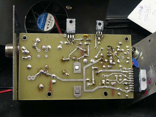
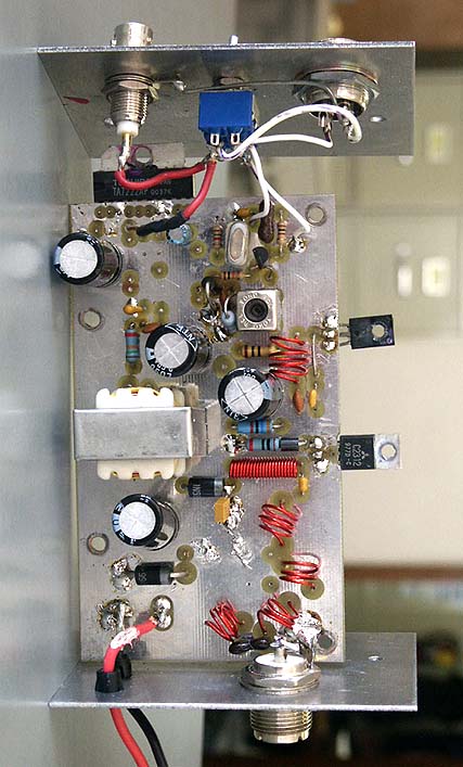
Plasma Sonics Ltd. Co. OM-1 Block Diagram Square Wave Audio In Audio Amp TA7222AP Modulation Transformer TF129 Driver 2SC1957 Oscillator 27.125 MHz Final 2SC2312
Cover Letter(s)
From: "Randal Clark" <[email protected]> Add to Address Book To: [email protected] Subject: FW: Non-Conformities FCC ID: RKYOM-1 (Ref # E04-000018-1) Date: Tue, 9 Mar 2004 13:31:24 -0800 FYI... Randal Clark Evaluation Engineer CKC Certification Services 4933 Sierra Pines Dr. Mariposa, CA 95338 Phone: (209) 742-2378 Fax: (209) 966-0857 Email: [email protected] CKC Certification Services provides US (FCC) and Canadian Certifications FAST! Go to http://www.ckccertification.com or http://www.ckc.com/ckccs.htm for more information. -----Original Message----- From: James Bare [mailto:[email protected] ] Sent: Monday, March 08, 2004 8:57 PM To: Randal Clark Subject: RE: Non-Conformities FCC ID: RKYOM-1 (Ref # E04-000018-1) Randy, Thanks for looking into this for me. Will contact Analab tomorrow about the problem. In the meantime here is what I've done about the defiencies. >Item 1. Please provide a revised confidentiality letter. Photos can >not be kept confidential, the letter must be signed and the date must >be current. Have made one up with new date, removed the words "pictures", and signed. Sent to your attention, also uploaded unsigned version to your web site . >Item 3. Please provide a revised user manual showing compliance to >ß18.213. I checked this and it seemed OK, did resend. Compliance info is at very end of the user manual. Wonder if she was looking at the wrong file ? >Item 5. Please provide a block diagram. Did forget this, made one up and sent to web site tonight. > >Item 6. Please provide a separate file for test set-up photos. Placed all set up photos into one PDF file and sent this afternoon. If there are any problems with these items, please let me know! If for some reason I need to have a partial test done at Analab for frequencies down to 20 MHz will there be any problems with accepting the data? I would think an entirely new report would have to be written including the new test data? Jim >Regarding the question on Loop antennae, this question refers to the >use of a loop antenna for radiated measurements below 30MHz as >specified in ANSI C63.4 2000. The FCC has recently announced that they >will not accept the use of Rod type antennae (including bicon or bilog >type) anywhere in this frequency range, despite earlier discussions of >allowing biconical antenna measurements within the range of 25-30MHz. > >The question stems from the test report from Analab, they claim that >the testing was performed from 20-400MHz, however they do not list for >their test equipment a magnetic loop antenna. You should contact the >testing laboratory and obtain clarification of the testing performed. >When following the procedures listed in ANSI C63.4, a shielded balanced >magnetic loop antenna should be used. Alternatively when following the >procedures listed in FCC MP-5, within the frequency range of 18 to 30 >MHz, a shielded balanced loop or calibrated tuned half-wave dipole is >acceptable. Analab lists both of these measurement procedures in the >test report, however do not provide adequate documentation to >substantiate the claim. > >Please feel free to contact me if you have any further questions >regarding these issues. > >All Best, > >Randal Clark >Evaluation Engineer > >CKC Certification Services >4933 Sierra Pines Dr. >Mariposa, CA 95338 >Phone: (209) 742-2378 >Fax: (209) 966-0857 >Email: [email protected] > >CKC Certification Services provides US (FCC) and Canadian >Certifications FAST! Go to http://www.ckccertification.com or >http://www.ckc.com/ckccs.htm for more information. > > >-----Original Message----- >From: James Bare [mailto:[email protected] ] >Sent: Sunday, March 07, 2004 10:20 PM >To: [email protected] >Subject: Re: Non-Conformities FCC ID: RKYOM-1 (Ref # E04-000018-1) > > >Hello, > >Will be happy to provide the following requests. Could you please >clarify a few points for me? > > >>The following items need to be provided before the evaluation for >>certification can be completed. If you have any questions please do >>not hestitate to contact CKC Certification Services at >>[email protected] . >> >>Item 1. Please provide a revised confidentiality letter. Photos can >>not be kept confidential, the letter must be signed and the date must >>be current. > >I would therefore assume that if the material requested to be kept >confidential is placed in a MS word document file instead of a jpg >picture, that this would comply with FCC guidelines? If so will revise >to comply. Please let me know! Will send you a signed copy of letter >with appropriate revisions. > >>Item 2. Please provide a signed copy of the CKC General Agreement >>Letter. > >You should have this, will provide my copy. >> >>Item 3. Please provide a revised user manual showing compliance to >>ß18.213. > >Wasn't this placed at the end of the user manual? Will check the file I >sent you. May have sent you an early version of the manual. > >>Item 4. The FCC requires the use of a loop antenna below 30MHz, please >>explain. > >Not certain what you mean. Do you mean for emission testing purposes or >for usage purposes ? If for usage purposes, loop antennas may or may >not be necessary. For example. > >Diathermy device - loop >Induction heater or welder - loop >Laser driver - non loop, direct attachment fired through electrodes. RF >pulsed field therapeutic device - gas plasma tube. Tubes are fired >through internal electrodes necessitating no loop, just direct >attachment to the electrodes. > >Maybe think in terms of the electrode fired tubes being akin to a >dipole? It is possible to light laser tubes and plasma tubes using >capacitive coupling wherein the tube is wrapped ( a loop on each end ). >Can provide pictures of this if required. Laser tubes however don't >tend to lase when wrapped in this manner. Sure do glow brightly though! > >> >>Item 5. Please provide a block diagram. > >Oops! Did forget to do this.Did send s…
Text truncated - open the document above for the full version.
Cover Letter(s)
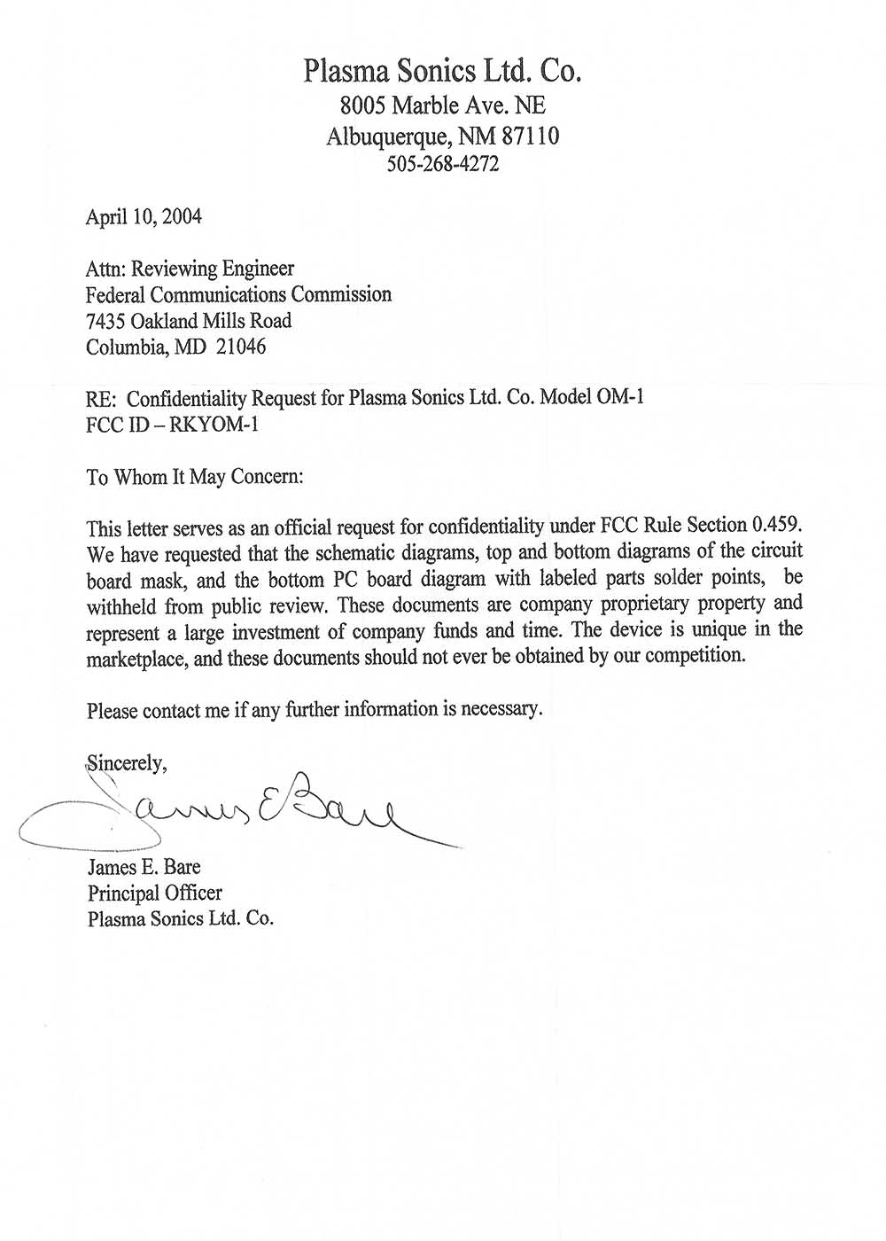
his message is not flagged. [ Flag Message - Mark as Unread ] From: "Randal Clark" <[email protected]> Add to Address Book To: "'James Bare'" <[email protected]> Subject: RE: Non-Conformities FCC ID: RKYOM-1 (Ref # E04-000018-1) Date: Mon, 8 Mar 2004 16:16:48 -0800 Hello Jim, Per our conversation earlier, I have asked Monika to review the confidentiality letter again and discuss any discrepancies with me regarding requested confidential material; please however have the letter signed and dated. Regarding the question on Loop antennae, this question refers to the use of a loop antenna for radiated measurements below 30MHz as specified in ANSI C63.4 2000. The FCC has recently announced that they will not accept the use of Rod type antennae (including bicon or bilog type) anywhere in this frequency range, despite earlier discussions of allowing biconical antenna measurements within the range of 25-30MHz. The question stems from the test report from Analab, they claim that the testing was performed from 20-400MHz, however they do not list for their test equipment a magnetic loop antenna. You should contact the testing laboratory and obtain clarification of the testing performed. When following the procedures listed in ANSI C63.4, a shielded balanced magnetic loop antenna should be used. Alternatively when following the procedures listed in FCC MP-5, within the frequency range of 18 to 30 MHz, a shielded balanced loop or calibrated tuned half-wave dipole is acceptable. Analab lists both of these measurement procedures in the test report, however do not provide adequate documentation to substantiate the claim. Please feel free to contact me if you have any further questions regarding these issues. All Best, Randal Clark Evaluation Engineer CKC Certification Services 4933 Sierra Pines Dr. Mariposa, CA 95338 Phone: (209) 742-2378 Fax: (209) 966-0857 Email: [email protected] CKC Certification Services provides US (FCC) and Canadian Certifications FAST! Go to http://www.ckccertification.com or http://www.ckc.com/ckccs.htm for more information. -----Original Message----- From: James Bare [mailto:[email protected] ] Sent: Sunday, March 07, 2004 10:20 PM To: [email protected] Subject: Re: Non-Conformities FCC ID: RKYOM-1 (Ref # E04-000018-1) Hello, Will be happy to provide the following requests. Could you please clarify a few points for me? >The following items need to be provided before the evaluation for >certification can be completed. If you have any questions please do >not hestitate to contact CKC Certification Services at >[email protected] . > >Item 1. Please provide a revised confidentiality letter. Photos can >not be kept confidential, the letter must be signed and the date must >be current. I would therefore assume that if the material requested to be kept confidential is placed in a MS word document file instead of a jpg picture, that this would comply with FCC guidelines? If so will revise to comply. Please let me know! Will send you a signed copy of letter with appropriate revisions. >Item 2. Please provide a signed copy of the CKC General Agreement >Letter. You should have this, will provide my copy. > >Item 3. Please provide a revised user manual showing compliance to >ß18.213. Wasn't this placed at the end of the user manual? Will check the file I sent you. May have sent you an early version of the manual. >Item 4. The FCC requires the use of a loop antenna below 30MHz, please >explain. Not certain what you mean. Do you mean for emission testing purposes or for usage purposes ? If for usage purposes, loop antennas may or may not be necessary. For example. Diathermy device - loop Induction heater or welder - loop Laser driver - non loop, direct attachment fired through electrodes. RF pulsed field therapeutic device - gas plasma tube. Tubes are fired through internal electrodes necessitating no loop, just direct attachment to the electrodes. Maybe think in terms of the electrode fired tubes being akin to a dipole? It is possible to light laser tubes and plasma tubes using capacitive coupling wherein the tube is wrapped ( a loop on each end ). Can provide pictures of this if required. Laser tubes however don't tend to lase when wrapped in this manner. Sure do glow brightly though! > >Item 5. Please provide a block diagram. Oops! Did forget to do this.Did send separate pictures of the various sections. > >Item 6. Please provide a separate file for test set-up photos. Odd, I was told that the pictures had to be separate. Actually had them all in one file originally for submission. Will place into one file. James Bare § 18.213 Information to the user. Information on the following matters shall be provided to the user in the in-struction manual or on the packaging if an instruction manual is not pro-vided for any type of ISM equipment: (a) The interference potential of the device or system (b) Maintenance of the system (c) Simple measures that can be taken by the user to correct inter-ference. [50 FR 36069, Sept. 5, 1985, as amended at 51 FR 17970, May 16, 1986]
Cover Letter(s)
This message is not flagged. [ Flag Message - Mark as Unread ] From: "Randal Clark" <[email protected]> Add to Address Book To: "'Monika Brandle'" <[email protected]> Subject: RE: Non-Conformities FCC ID: (Ref # E04-00002-1) Date: Mon, 8 Mar 2004 10:34:40 -0800 Thank you Mo, I took a look at the confidentiality letter with the customer this morning. It appears that what he is requesting is legitimate. He worded the letter calling the schematics, block diagrams and PCB etchings "Photos" Could you take another look at that and make sure i'm not missing something. I'm looking into the measurements under 30MHz issue. Something came out about this recently; if they used a bicon down to 20 MHz and it was calibrated to that frequency, then i do not think there's a probem. -- I'll check around for some things. Thanks, Randy. -----Original Message----- From: Monika Brandle [mailto:[email protected]] Sent: Monday, March 08, 2004 6:38 AM To: [email protected] Cc: [email protected] Subject: Non-Conformities FCC ID: (Ref # E04-00002-1) The following items are still needed to complete the evalulation for your product. Please send this information to [email protected] . Item 1. Please upload a signed copy of the Indemnification and Liability Statement. An example has been provided. Item 2. Please provide an updated label using the new format US: ABCWT02B12345678 Where: ABC- Responsible Party Code (RPC) WT- Equipment Code 02B - AC Ringer Equivalence Number (REN) 12345678-Product Identifier Item 3. Please provide the following for the US service agent. Company Name Individual or Department Address City, State, Zip Phone URL: Item 4. Please confirm/answer the following questions Network address signaling code AC Ringer Equivalence Number – USOC Jacks – Hearing Aid Compatibility - Repetitive Dialing to a Single Number – Facility Interface Code(s)- Manufacturer Port ID – Service Order Codes (SOC)- Answer Supervision – Ancillary Equipment – (Certification Status, Trade Name, Model Number, Type, Manuf ID) I will send the ACTA submission form, which provides an explanation and example of the items stated above. The items indicated above must be submitted before processing can continue on the referenced application. Failure to provide the requested information within 60 days may result in application dismissal pursuant to Section 2.917(c) and forfeiture of the filing fee pursuant to Section 1.1106. Thank you Kindly, Monika Brandle Do you Yahoo!? Yahoo! Search - Find what you’re looking for faster.
Cover Letter(s)
As Inline Text As Attachment Reply To Sender Reply To Everyone Yahoo! My Yahoo! Mail Search Welcome, monikabrandle [Sign Out , My Account] Mail Home - Help Click Here Mail Addresses Calendar Notepad [email protected] [Sign Out] Check Mail Compose Mail Upgrades - Search Mail - Mail Options Folders [Add] Inbox (14) Draft Sent Bulk [Empty] Trash [Empty] My Folders [Hide] Application Com... EMC Related Info Email Conformat... GI BILL INFO Job References Job Tips Microsoft Monster.Com TCB Previous | Next | Back to Messages Printable View - Full Headers Delete This message is not flagged. [ Flag Message - Mark as Unread ] From: "Randal Clark" <[email protected]> Add to Address Book To: [email protected] Subject: FW: Non-Conformities FCC ID: RKYOM-1 (Ref # E04- 000018-1) Date: Tue, 9 Mar 2004 13:31:24 -0800 [email protected] CKC Certification Services provides US (FCC) and Canadian Certifications FAST! Go to http://www.ckccertification.com or Check out your credit for Free Refinance now for under 3%! Apply for a Personal Loan! A Good Card for Bad Credit! http://www.ckc.com/ckccs.htm for more information. ----- Original Message----- From: James Bare [mailto:[email protected]] Sent: Monday, March 08, 2004 8:57 PM To: Randal Clark Subject: RE: Non-Conformities FCC ID: RKYOM-1 (Ref # E04-000018- 1) Randy, Thanks for looking into this for me. Will contact Analab tomorrow about the problem. In the meantime here is what I've done about the defiencies. >Item 1. Please provide a revised confidentiality letter. Photos can >not be kept confidential, the letter must be signed and the date must >be current. Have made one up with new date, removed the words "pictures", and signed. Sent to your attention, also uploaded unsigned version to your web site . >Item 3. Please provide a revised user manual showing compliance to >ß18.213. I checked this and it seemed OK, did resend. Compliance info is at very end of the user manual. Wonder if she was looking at the wrong file ? >Item 5. Please provide a block diagram. Did forget this, made one up and sent to web site tonight. > >Item 6. Please provide a separate file for test set-up photos. Placed all set up photos into one PDF file and sent this afternoon. If there are any problems with these items, please let me know! If for some reason I need to have a partial test done at Analab for frequencies down to 20 MHz will there be any problems with accepting the data? I would think an entirely new report would have to be written including the new test data? Jim >Regarding the question on Loop antennae, this question refers to the >use of a loop antenna for radiated measurements below 30MHz as >specified in ANSI C63.4 2000. The FCC has recently announced that they >will not accept the use of Rod type antennae (including bicon or bilog >type) anywhere in this frequency range, despite earlier discussions of >allowing biconical antenna measurements within the range of 25- 30MHz. > >The question stems from the test report from Analab, they claim that >the testing was performed from 20- 400MHz, however they do not list for >their test equipment a magnetic loop antenna. You should contact the >testing laboratory and obtain clarification of the testing performed. >When following the procedures listed in ANSI C63.4, a shielded balanced >magnetic loop antenna should be used. Alternatively when following the >procedures listed in FCC MP-5, within the frequency range of 18 to 30 >MHz, a shielded balanced loop or calibrated tuned half-wave dipole is >acceptable. Analab lists both of these measurement procedures in the >test report, however do not provide adequate documentation to >substantiate the claim. > >Please feel free to contact me if you have any further questions >regarding these issues. > >All Best, > >Randal Clark >Evaluation Engineer > >CKC Certification Services >4933 Sierra Pines Dr. >Mariposa, CA 95338 >Phone: (209) 742-2378 >Fax: (209) 966-0857 >Email: [email protected] > >CKC Certification Services provides US (FCC) and Canadian >Certifications FAST! Go to http://www.ckccertification.com or >http://www.ckc.com/ckccs.htm for more information. > > >-----Original Message----- >From: James Bare [mailto:[email protected]] >Sent: Sunday, March 07, 2004 10:20 PM >To: [email protected] >Subject: Re: Non-Conformities FCC ID: RKYOM-1 (Ref # E04-000018-1) > > >Hello, > >Will be happy to provide the following requests. Could you please >clarify a few points for me? > > >>The following items need to be provided before the evaluation for >>certification can be completed. If you have any questions please do >>not hestitate to contact CKC Certification Services at >>[email protected]. >> >>Item 1. Please provide a revised confidentiality letter. Photos can >>not be kept confidential, the letter must be signed and the date must >>be current. > >I would therefore assume that if the material requested to be kept >confidential is placed in a MS word document file instead of a jpg >picture, that this would comply with FCC guidelines? If so will revise >to comply. Please let me know! Will send you a signed copy of letter >with appropriate revisions. > >>Item 2. Please provide a signed copy of the CKC General Agreement >>Letter. > >You should have this, will provide my copy. >> >>Item 3. Please provide a revised user manual showing compliance to >>ß18.213. > >Wasn't this placed at the end of the user manual? Will check the file I >sent you. May have sent you an early version of the manual. > >>Item 4. The FCC requires the use of a loop antenna below 30MHz, please >>explain. > >Not certain what you mean. Do you mean for emission testing purposes or >for usage purposes ? If for usage purposes, loop antennas may or may >not be necessary. For example. > >Diathermy device - loop >Induction heater or welder - loop >Laser driver - non loop, direct attachment fired through electrodes. RF >pulsed field …
Text truncated - open the document above for the full version.
Operational Description
Operational Description OM-1 The OM-1 is a high level AM transmitter operating on the ISM band at 27.125 MHz. The OM-1 is designed to be driven into over-modulation using square wave audio modulation. The intent, is the production of a pulsed wave output. This output will have a significant percentage of the total power of the transmitter being located within the sidebands and not within the carrier. The OM-1 can be used for stand alone operation, or with amplifiers which have appropriate RF harmonic limiter circuits. The majority of the transmitters power is located within the side bands making the demodulated signal of the OM-1 extremely intense. The output of the OM-1 could be compared to that of a gated CW transmitter. A gated CW transmitter will have only 25 to 33% of it’s total power located within the sidebands. The other 2/3 rd of the CW transmitters power is in the carrier. Meaning to achieve the same demodulated signal strength on a watt per watt basis, the CW transmitter is less than half as efficient as the OM-1. The demodulated signal strength from a 80 watt P-P gated CW transmitter would be equaled by the 30 watt P-P power of the OM-1. The extreme over modulation utilized by the OM-1 makes it useless for voice communication. The use of square wave modulation means the demodulated signal should also be a square wave, and thus undistorted. The OM-1 needs a minimum 50% duty cycle square wave for proper operation. Best results are obtained with a 70% duty cycle square wave. The pulse envelope formed by over modulation is not overly responsive to the duty cycle of the modulating square wave. The maximum output pulse width will approximately have a 55% duty cycle. Pulsed Output of the OM-1
Parts List/Tune Up Info
Parts List For OM-1 Transmitter By Plasma Sonics Ltd. Co. Resistors R1 100 ¼ watt R2 10K ¼ watt R3 1.5K ¼ watt R4 0.50 1 watt ( Stand on End ) R5 15K ¼ watt R6 10 ½ watt R7 37 ½ watt R8 10 ½ watt IC, Diodes, Crystal, and Transistors IC1 TA7222AP D1 1N5822 Shottkey - Polarity D2 1N5822 Shottkey - Isolation D3 1N5350 Zener – 5w / 13 V Stand on End Tr1 2N3904 Tr2 2SC1957 Tr3 2SC 2312 CR 27.125 MHz Switches, Connectors, Transformer, Jumper, Fan, RF Choke SW-1 DPDT J-1 BNC J-2 4 Pin microphone style J-3 SO239 T1 TF-129 or Robyn 110004 JV1 Wire Jumper F-1 Fuse and Holder ATC 5 amp CH-1 Type 61 RF choke FN 3 1/8 th inch square 13.8V box fan and guard Inductors L1 4T .278 μh L2 21T .668 μh L3 3T .176 μh L4 3T .176 μh L5 3T .176 μh L6 3T .176 μh L7 Ferrite bead L8 Toko RCL LA208 or KEI 114 AP-1 Capacitors C1 3300 uf 16V Electrolytic C2 3300 uf 16V Electrolytic C3 470 uf 63V Electrolytic C4 4700 uf 16V Electrolytic C5 47 uf 25V Electrolytic C6 47 uf 16V Polarized Tantalum C7 100 pf 500V Silver Mica C8 130 pf 500V Silver Mica C9 151 pf monolithic ceramic - Top of board paired with C10 C10 151 pf monolithic ceramic - Bottom of board – paired with C9 C11 393K monolithic ceramic – (rectangular) Bottom of board between L2 ( diode D 2 end ) and R8 ( Ground End), or can attach on top of board between D2/L2 and ground. C12 103 ceramic disc C13 103 ceramic disc C14 .001 ceramic disc C15 104 monolithic ceramic C16 104 monolithic ceramic Tune Up Info The OM-1 is extremely stable and should need no adjustment over it’s operational lifetime. The oscillator circuit is fixed and non adjustable. Adjustment of L-8 will result in minimal changes to the modulated and un modulated power levels. In the consequence of component failure, the OM-1 is simple to tune, areas of potential problem are with the two RF transistors and the Audio Chip. Failure of the audio chip and replacement will need no adjustment of the OM-1. If either the final or driver transistors fail, replace the faulty tr…
Text truncated - open the document above for the full version.
Contact Information
Applicant
James E. Bare(Principal Officer)
Technical Contact
Plasma Sonics Ltd. CoJames Bare
[email protected]505-268-4272
8005 Marble Ave. NE · Albuquerque, New Mexico · United States
Non-Technical Contact
Plasma Sonics Ltd. CoJames Bare
[email protected]505-268-4272
Test Firm
Analab Llc.Jason Smith
Technical Specifications
| # | Rule Parts | Frequency Range | Power Output |
|---|---|---|---|
| 1 | 18 | 27.125 MHz - 27.125 MHz | 32 W |