RLBACS320000Access Control System
The Stanley Works Israel LTD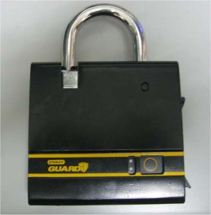
Click to zoom
Application Details
- Equipment Class
- DCD - Part 15 Low Power Transmitter Below 1705 kHz
- Date of Grant
- Feb 25, 2013
- Application Purpose
- Original Equipment
- Date of Application
- Feb 24, 2013
- Equipment Note
- Access Control System
- Frequency Range
- 0.12500000 - 0.12500000
- Company
- The Stanley Works Israel LTD
- Country
- Israel
Documents & Files
Document Text
Text extracted from the exhibit documents filed with the FCC. Open a document above to read the original.
Users Manual
Access Control System STST1-79226, STST320000 STST1-71238, STST321000 Communication - USB & Bluetooth (for ACS-BT) activation FR Communication - USB & Bluetooth (for ACS-BT) activation IT Communication - USB & Bluetooth (for ACS- BT) activation ES Communication - USB & Bluetooth (for ACS-BT) activation DE Communication - USB & Bluetooth (for ACS-BT) activation SE Communication - USB & Bluetooth (for ACS-BT) activation DK Communication - USB & Bluetooth (for ACS-BT) activation Lock opened / remove users FR Lock opened / remove users IT Lock opened / remove users ES Lock opened / remove users DE Lock opened / remove users SE Lock opened / remove users DK Lock opened / remove users Add new user / Pairing access control FR Add new user / Pairing access control IT Add new user / Pairing access control ES Add new user / Pairing access control DE Add new user / Pairing access control SE Add new user / Pairing access control DK Add new user / Pairing access control A B C D E F G H A) The lock - main unit B) Key x2 C) User tag x4 D) Cutter shield (Note: not included in pack - see label) E) Batteries x2 F) USB cable G) User manual H) Extended user manual FRXX A) The lock - main unit B) Key x2 C) User tag x4 D) Cutter shield (Note: not included in pack - see label) E) Batteries x2 F) USB cable G) User manual H) Extended user manual DEXX A) The lock - main unit B) Key x2 C) User tag x4 D) Cutter shield (Note: not included in pack - see label) E) Batteries x2 F) USB cable G) User manual H) Extended user manual ITXX A) The lock - main unit B) Key x2 C) User tag x4 D) Cutter shield (Note: not included in pack - see label) E) Batteries x2 F) USB cable G) User manual H) Extended user manual SEXX A) The lock - main unit B) Key x2 C) User tag x4 D) Cutter shield (Note: not included in pack - see label) E) Batteries x2 F) USB cable G) User manual H) Extended user manual ESXX A) The lock - main unit B) Key x2 C) User tag x4 D) Cutter shield (Note: not included in pack - see label) E) Batteries x2 F) USB cable G) User manual H) Extended user manual DKXX A) The lock - main unit B) Key x2 C) User tag x4 D) Cutter shield (Note: not included in pack - see label) E) Batteries x2 F) USB cable G) User manual H) Extended user manual GB XX Key In - Insert or remove mechanical key FR Key In - Insert or remove mechanical key IT Key In - Insert or remove mechanical key ES Key In - Insert or remove mechanical key DE Key In - Insert or remove mechanical key SE Key In - Insert or remove mechanical key DK Key In - Insert or remove mechanical key 01 TOP vIEw BOTTOm vIEw FROnT vIEw SIDE vIEw FROnT vIEw 1) Shackle release button 2) Indication LEDs 3) Push button TOP vIEw 4) Mechanical latch 5) Battery cover screw release 6) Electromechanical latch 7) Shackle protector screw thread BOTTOm vIEw 8) Battery cover 9) User tag slot SIDE vIEw 10) Key insertion slot 11) USB input GB FROnT vIEw 1) Shackle release button 2) Indication LEDs 3) Push button TOP vIEw 4) Mechanical latch 5) Battery cover screw release 6) Electromechanical latch 7) Shackle protector screw thread BOTTOm vIEw 8) Battery cover 9) User tag slot SIDE vIEw 10) Key insertion slot 11) USB input FR FROnT vIEw 1) Shackle release button 2) Indication LEDs 3) Push button TOP vIEw 4) Mechanical latch 5) Battery cover screw release 6) Electromechanical latch 7) Shackle protector screw thread BOTTOm vIEw 8) Battery cover 9) User tag slot SIDE vIEw 10) Key insertion slot 11) USB input IT FROnT vIEw 1) Shackle release button 2) Indication LEDs 3) Push button TOP vIEw 4) Mechanical latch 5) Battery cover screw release 6) Electromechanical latch 7) Shackle protector screw thread BOTTOm vIEw 8) Battery cover 9) User tag slot SIDE vIEw 10) Key insertion slot 11) USB input DE FROnT vIEw 1) Shackle release button 2) Indication LEDs 3) Push button TOP vIEw 4) Mechanical latch 5) Battery cover screw release 6) Electromechanical latch 7) Shackle protector screw thread BOTTOm vIEw 8) Battery cover 9) User tag slot SIDE vIEw 10) Key insertion slot 11) USB input ES FROnT vIEw 1) Shackle release button 2) Indication LEDs 3) Push button TOP vIEw 4) Mechanical latch 5) Battery cover screw release 6) Electromechanical latch 7) Shackle protector screw thread BOTTOm vIEw 8) Battery cover 9) User tag slot SIDE vIEw 10) Key insertion slot 11) USB input SE FROnT vIEw 1) Shackle release button 2) Indication LEDs 3) Push button TOP vIEw 4) Mechanical latch 5) Battery cover screw release 6) Electromechanical latch 7) Shackle protector screw thread BOTTOm vIEw 8) Battery cover 9) User tag slot SIDE vIEw 10) Key insertion slot 11) USB input DK 1 289 4 67 10 11 5 3 • Keeping your valuable equipment safe and accounted for is crucial. • the neW locK is the best Way to control your Job site. • the locK is easily programmed to open up during set hours and only to the authorized WorKers With user tags. • the log registers the entries. • softWare and mobile application enabels managing WorKers details and controlling the locK*. THAnK yOu FOR CHOOSInG THE STAnlEy GuARD ACCESS COnTROl SySTEm. InSTAllInG THE BATTERy SET uP AnD InSTAllATIOn 2 Insert the mechanical key and rotate it clockwise till lock is opened. open the screw beneath the latch. 1 45 6 remove battery cover. Place battery cover back on and close the screw tightly in clockwise direction. the lock is ready for operation. * software not included/ mobile application included with the ACS BT 3 02 insert cr123a batteries. make sure that battery (-) is facing the springs. 1. please copy and keep the code marked on the key. 2. In case of key is lost, contact the customer service to order a new one. you will need to advise the code. 3. There is a spare key so you can also duplicate the key. 4. In case there is no key and also no code is at hand - the cylinder will need to be replaced. please contact customer service to send your lock to be fixed or arrive there to do so. InSTAllInG THE BATTERy 2 Insert the mechanical key and rotate it counter-clockwise to …
Text truncated - open the document above for the full version.
Cover Letter(s)
February 21, 2013 To: Telefication B.V. Attn: Dept. FCC TCB Edisonstraat 12A 6902 PK ZEVENAAR The Netherlands Subject: Application for certification of a Access Control System FCC ID:RLBACS320000 Dear Gentlemen, Please find attached our application for certification of a Access Control System, model ACS 320000, FCC ID:RLBACS320000, prepared in accordance with FCC Rules, parts 2 and 15, section 15.209. The product testing and this application for certification were performed by Hermon Laboratories, which is listed by FCC (Registration Numbers 90623, 90624). The FCC Designation Number is US1003. Hermon Labs responsible person is Mr. Michael Nikishin, tel: 011 972 4626 8440, fax:011 972 4628 8277, e-mail: [email protected]. We hope this application satisfies your requirements. Please send an invoice to Hermon Labs. Sincerely, Mrs. Irit Teerosh QA & EHS Manager The Stanley Works Israel Ltd.
External Photos
The Stanley Works Israel Ltd. FCC ID:RLBACS320000 Page 1 of 5 EXTERNAL PHOTOGRAPHS This document contains 4 photographs The Stanley Works Israel Ltd. FCC ID:RLBACS320000 Page 2 of 5 Photograph No.1 Access control system general view The Stanley Works Israel Ltd. FCC ID:RLBACS320000 Page 3 of 5 Photograph No.2 Access control system rear side view The Stanley Works Israel Ltd. FCC ID:RLBACS320000 Page 4 of 5 Photograph No.3 Access control system side view The Stanley Works Israel Ltd. FCC ID:RLBACS320000 Page 5 of 5 Photograph No.4 Access control system side view
ID Label/Location Info
The Stanley Works Israel Ltd. FCC ID:RLBACS320000 Page 1 of 1 Label Label location Label with FCC ID:RLBACS320000 will be located at the device rear side. FCC ID:RLBACS320000
Internal Photos
The Stanley Works Israel Ltd. FCC ID:RLBACS320000 Page 1 of 7 INTERNAL PHOTOGRAPHS This document contains 6 photographs The Stanley Works Israel Ltd. FCC ID:RLBACS320000 Page 2 of 7 Photograph No.1 Access control system module internal view The Stanley Works Israel Ltd. FCC ID:RLBACS320000 Page 3 of 7 Photograph No.2 Access control system rear side view The Stanley Works Israel Ltd. FCC ID:RLBACS320000 Page 4 of 7 Photograph No.3 Main PCB front view The Stanley Works Israel Ltd. FCC ID:RLBACS320000 Page 5 of 7 Photograph No.4 Main PCB front view The Stanley Works Israel Ltd. FCC ID:RLBACS320000 Page 6 of 7 Photograph No.5 Antenna close view The Stanley Works Israel Ltd. FCC ID:RLBACS320000 Page 7 of 7 Photograph No.6 Main PCB second side view
Operational Description
The Stanley Works Israel Ltd. FCC ID:RLBACS320000 1 Access control system System Overview General Description An access control system is a smart padlock for preventing unauthorized access of strangers and workers to storage facilities and containers at jobsites. Access to the padlock is enabled using a mechanical key and user tags (LF 125 kHz RFID tags) for users identifications. The system can be connected to PC using USB cable. The connection allows to manage the users database, control system settings and download log of events. The device is powered using two CR123A (2 x 3V) non‐rechargeable batteries. Diagram 1: System components overview System functionality Enables locking and unlocking the padlock using mechanical key and RFID user tags. Preventing access from unauthorized people. Hold log records of last operations that was performed. Enables USB communication for management and control. The Stanley Works Israel Ltd. FCC ID:RLBACS320000 2 Hardware Block Diagram The Stanley Works Israel Ltd. FCC ID:RLBACS320000 3 Hardware modules: MCU (STM32L151RBT6) ‐ An ARM Cortex M3 MCU is connected to 2 crystal oscillators. The core is driven by 16 MHz osc which is multiplied by internal PLL to yield frequency of 24 MHz. The USB core frequency is multiplied by the PLL to achieve 48 MHz. The second crystal oscillator provides frequency of 32.768 kHz to feed the RTC core. Motor Driver (DRV8832DGQ) ‐ An IC dedicated for driving the motor, changing rotation direction and motor stall sensing. Motor (12GF‐1215) ‐ An electromechanical device which converts electrical energy to rotational energy (torque). The electrical motor will open/ close the electromechanical latch upon command from the MCU. Buzzer (GT‐0905A)‐ Magnetic transducer, An audio signaling device, used as part of the UI. 125 kHz LF RFID reader(MLX90109) ‐ A module that reads the RFID tag (EM4100 protocol). The reader generates frequency of approx. 125 kHz to energize the passive RFID tag. EEPROM memory (24AA256) ‐ External memory IC that contains locks DB, configurations and LOG. Push Button ‐ Mechanical switch for lock control. LEDs ‐ A semi conductor light sources, part of the user interface. Encoder (EC10E1220501) ‐ An electromechanical device to determine the scroll position. IR LED + Photo transistor (GP1S094HCZ0F) ‐ Used to reset scroll position (find the zero point). USB ‐ USB connector for serial USB communication. Power Management ‐ Module that supplies power to all hardware modules and performs battery voltage measurements. Contains MCP1702T LDO. The Stanley Works Israel Ltd. FCC ID:RLBACS320000 4 The MCU ‐ STM32L151R8T6 is an ultra low power ARM based 32‐bit MCU that controls all system functionality. The MCU is powered using LDO which feeds it with regulated 3.3V. When there is no user interaction with the system the MCU enters sleep mode in which it draws current of 50uA and all other peripheral modules are turned off. The MCU wakes upon external interrupts from the Push Button and the Encoder and also upon internal timer. When the MCU is in active mode it draws current of 10mA @ 24MHz. The MCU core is fed with 16MHz crystal oscillator (Y2) which is multiplied using internal PLL to obtain frequency of 24MHz. The MCU also has a USB peripheral which feeds from 48MHz clock, this clock frequency is obtained by multiplying the 16MHz with internal PLL. The 32.768KHz crystal (Y1) is active at all time (when power is applied) and drives the internal RTC core. The firmware of the MCU is programmed using the JTAG connector. There is also a UART port for DEBUG (P4). The system contains an 256 Kbit EEPROM IC for storing users' database and log records. The EEPROM is powered from 3.3V LDO and can be switched off when not in use using Q10. The EEPROM communicates with the MCU using I2C interface. The DRV8832 provides an integrated motor driver solution for battery‐powered toys, printers, and other low‐voltage or battery‐powered motion control applications. The device has one H‐bridge driver, and can drive one DC motor or one winding of a stepper motor, as well as other loads like solenoids. The output driver block consists of N‐channel and P‐channel power MOSFET’s configured as an H‐bridge to drive the motor winding. The motor driver is used to drive a small DC motor that opens and closes the electromechanical latch. The motor is connected to JMOT connector. The motor driver is controlled by the MCU using two digital pins IN1 and IN2, and its power is fed directly from the battery or the USB port. It is configured in hardware to regulate the motor voltage using internal PWM to 5.1V or less (depends on power source USB or battery). The RFID module was designed to read passive RFID tags ‐ EM4100 protocol. This module generates carrier with frequency of 125 kHz to power the passive tag using an analog front end IC ‐ MLX90109 which also decodes the received signal from the tag. The transferred data rate is 2 Kbps with Manchester ASK modulation. The RFID module is active only when an RFID tag with a magnet is inserted to ACS dedicated slot. The magnet inside the tag triggers the reed switch which cause the MCU to activate the MLX90109 to produce 125 kHz frequency. MLX90109 is switched using the MOSFET transistor Q6. 125 kHz frequency is obtained using a parallel LC antenna which yields resonant frequency of 125 kHz. MLX90109 is powered from 3.3V driven from LDO. 0 11 125.074 22 22 73.6 fKHz LCnFuH The Stanley Works Israel Ltd. FCC ID:RLBACS320000 5 The voltage on MODU pin controls the amplitude of the antenna as follows: VMODU is set to a constant value by the resistors R31 and R26. Communication between MCU and MLX90109 obtained using two wire open drain serial communication. Coil Antenna Specifications ParameterSymbol Min TypMaxUnits Coil InductanceL7073.777uH Coil ResitanceR L 1.581.671.75Ohm Coil HeighH-2.863mm Outside diameterOD--18.9mm Inside diameterID16.91717.5mm Lead LengthLL20mm Tin Plated …
Text truncated - open the document above for the full version.
Test Report
Hermon Laboratories Ltd. Harakevet Industrial Zone, Binyamina 30500, Israel Tel. +972-4-6288001 Fax. +972-4-6288277 E-mail: [email protected] Page 1 of 21 Report ID: STARAD_FCC.24133.docx Date of Issue: 17-Feb-13 ELECTRICAL TESTING 0839.01 TEST REPORT ACCORDING TO: FCC 47CFR part 15 subpart C § 15.209 FOR: The Stanley Works Israel Ltd. Access Control System Model: ACS 320000 FCC ID:RLBACS320000 This report is in conformity with ISO/ IEC 17025. The "A2LA Accredited" symbol endorsement applies only to the tests and calibrations that are listed in the scope of Hermon Laboratories accreditation. The test results relate only to the items tested. This test report shall not be reproduced in any form except in full with the written approval of Hermon Laboratories Ltd. Report ID: STARAD_FCC.24133.docx Date of Issue: 17-Feb-13 Page 2 of 21 Table of contents 1 Applicant information ..................................................................................................................................................... 3 2 Equipment under test attributes .................................................................................................................................... 3 3 Manufacturer information .............................................................................................................................................. 3 4 Test details .................................................................................................................................................................... 3 5 Tests summary .............................................................................................................................................................. 4 6 EUT description ............................................................................................................................................................. 5 6.1 General information ....................................................................................................................................................... 5 6.2 Operating frequencies ................................................................................................................................................... 5 6.3 Test configuration .......................................................................................................................................................... 5 6.4 Changes made in EUT .................................................................................................................................................. 5 7 Transmitter tests according to 47CFR part 15 subpart C requirements ........................................................................ 6 7.1 Field strength of emissions ............................................................................................................................................ 6 7.2 Antenna requirements ................................................................................................................................................. 13 8 APPENDIX A Test equipment and ancillaries used for tests ....................................................................................... 14 9 APPENDIX B Measurement uncertainties ................................................................................................................... 15 10 APPENDIX C Test laboratory description ................................................................................................................... 16 11 APPENDIX D Specification references ....................................................................................................................... 16 12 APPENDIX E Test equipment correction factors ......................................................................................................... 17 13 APPENDIX F Abbreviations and acronyms ................................................................................................................. 21 Report ID: STARAD_FCC.24133.docx Date of Issue: 17-Feb-13 Page 3 of 21 1 Applicant information Client name: The Stanley Works Israel Ltd. Address: 19 Hamelacha street, New Industrial Zone, Rosh Ha’ayin 48091, Israel Telephone: +972 3902 0200 Fax: +972 3902 0222 E-mail: [email protected] Contact name: Mrs. Irit Teerosh 2 Equipment under test attributes Product name: Access control system Model(s): ACS Serial number: 00-00-00-00-76 Hardware version: N1.01 Software release: N1.06 Receipt date 1/28/2013 3 Manufacturer information Manufacturer name: The Stanley Works Israel Ltd. Address: 19 Hamelacha street, New Industrial Zone, Rosh Ha’ayin 48091, Israel Telephone: +972 3902 0200 Fax: +972 3902 0222 E-Mail: [email protected] Contact name: Mrs. Irit Teerosh 4 Test details Project ID: 24133 Location: Hermon Laboratories Ltd. Harakevet Industrial Zone, Binyamina 30500, Israel Test started: 1/28/2013 Test completed: 1/29/2013 Test specification(s): FCC 47CFR part 15, subpart C, §15.209 Report ID: STARAD_FCC.24133.docx Date of Issue: 17-Feb-13 Page 4 of 21 5 Tests summary Test Status Transmitter characteristics Section 15.209, Field strength of emissions Pass Section 15.207(a), Conducted emission Not required Section 15.203, Antenna requirements Pass Testing was completed against all relevant requirements of the test standard. The results obtained indicate that the product under test complies in full with the requirements tested. The test results relate only to the items tested. Pass/ fail decision was based on nominal values. Name and Title Date Signature Tested by: Mr. S.Samokha, test engineer January 29, 2013 Reviewed by: Mrs. M. Cherniavsky, certification engineer February 17, 2013 Approved by: Mr. M. Nikishin, EMC and Radio group leader February 20, 2013 Report ID: STARAD_FCC.24133.docx Date of Issue: 17-Feb-13 Page 5 of 21 6 EUT description 6.1 General information The EUT, Access Control System,…
Text truncated - open the document above for the full version.
Test Setup Photos
The Stanley Works Israel Ltd. FCC ID:RLBACS320000 Page 1 of 3 SETUP PHOTOGRAPHS This document contains 2 photographs The Stanley Works Israel Ltd. FCC ID:RLBACS320000 Page 2 of 3 Photograph No.1 Setup for field strength measurements in the anechoic chamber below 30 MHz The Stanley Works Israel Ltd. FCC ID:RLBACS320000 Page 3 of 3 Photograph No.2 Setup for spurious emission field strength measurements in the anechoic chamber in 30 – 1000 MHz range
Contact Information
Applicant
Irit Teerosh(Mrs)
Technical Contact
Hermon Laboratories Ltd.Michael Nikishin
[email protected]972 4626 8440
Harakevet Industrial zone · Israel
Non-Technical Contact
The Stanley Works Israel Ltd.Irit Teerosh
[email protected]972 3902 0200
Test Firm
Hermon Laboratories Ltd.Alexander Usoskin
Technical Specifications
| # | Rule Parts | Frequency Range | Power Output |
|---|---|---|---|
| 1 | 15C | 0.125 MHz - 0.125 MHz | - |
Other Applications from The Stanley Works Israel LTD
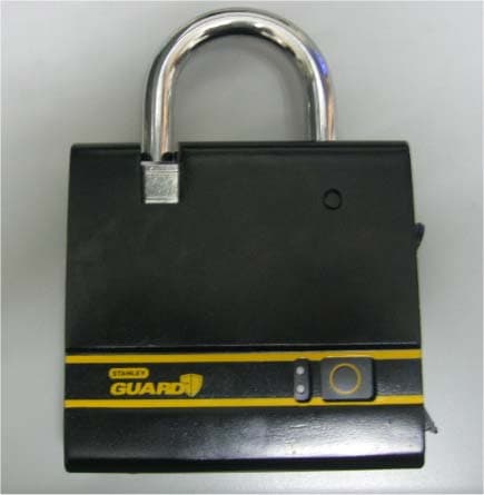
RLBACS321000
Mar 04, 2013Access Control System
Equipment Class
DCD - Part 15 Low Power Transmitter Below 1705 kHz